Thermal-hydraulic performance of convective boiling jet array
impingement
R. Jenkins, C. De Brún, R. Kempers, R Lupoi, A. J. Robinson
E-mail: [email protected] (A.J. Robinson)
Keywords: Heat transfer, impinging jet, boiling heat transfer, two phase flow, electronics cooling
Abstract —jet impingement boiling is investigated with regard to heat transfer and pressure drop performance using a novel laser sintered 3D printed jet impingement manifold design. Water was the working fluid at atmospheric pressure with inlet subcooling of 7oC. The convective boiling performance of the impinging jet system was investigated for a flat copper target surface for 2700≤Re≤5400. The results indicate that the heat transfer performance of the impinging jet is independent of Reynolds number for fully developed boiling. Also, the investigation of nozzle to plate spacing shows that low spacing delays the onset of nucleate boiling causing a superheat overshoot that is not observed with larger gaps. However, no sensitivity to the gap spacing was measured once boiling was fully developed. The assessment of the pressure drop performance showed that the design effectively transfers heat with low pumping power requirements. In particular, owing to the insensitivity of the heat transfer to flow rate during fully developed boiling, the coefficient of performance of jet impingement boiling in the fully developed boiling regime deteriorates with increased flow rate due to the increase in pumping power flux.
1. Introduction
Air cooling of high performance electronic components is becoming progressively more obsolete. The poor thermophysical properties of air coupled with space and acoustic limitations have meant that the performance of conventional fan and heat sink based cooling systems have, in many cases, reached their limitation. Heat fluxes in excess of 1kW/cm2 are expected in the near future from high performance electronics [1] and therefore higher performing cooling methodologies must be adopted to accommodate the increasing power densities. As a result, there is a requirement for technologies which can effectively cool small surface areas and reduce temperature gradients to acceptable levels with scalable technologies and designs which can be incorporated into practical electronic packages.
Two cooling methods that are thought to have the potential to meet these requirements are liquid cooled microchannels and liquid jet impingement. For microchannels, single phase heat transfer has provided extremely high heat transfer performance recently [2], but large pressure drops and temperature gradients along the heated surfaces are technical drawbacks inhibiting this particular technology. However, Kandlikar et. al [3] has shown that two phase flow using an OMM (open microchannel manifold) designs provided excellent heat flux dissipation potential at moderate pressure drops, while Zhao et al. [4] have shown jet impingement to outperform the OMM considerably from a heat transfer perspective.
which are then subsequently augmented by bubble activity during boiling; that being the aggressive mixing created by the bubbles that are generated and forced across the heated surface [5].
Peles et al. [4] and Cardenas and Naranyanan [11] determined that, with water as the working fluid, the fully developed boiling jet impingement performance is independent of Reynolds number. However, with highly wetting fluids, such as R134a, the performance during fully developed boiling was found to be dependent on the Reynolds number [12, 13], with the higher Reynolds numbers providing better heat transfer performance. This partially confirmed the earlier work of Wolf et al. [5] who noted that the heat transfer performance was dependent only on the characteristics of the surface and the liquid used rather than on the jet velocity, subcooling, nozzle or heater dimensions [6]. However, it was noted that the critical heat flux (CHF) was dependent on the jet velocity, of the form q//CHF~U
1/3
. In the study, Wolf et al.
investigated local heat transfer performance using a single free surface jet of water. Liquid subcooling was found to increase the critical heat flux of boiling impinging jet systems [8, 9], while at the same time reducing bubble size and aided in keeping the surface wetted [10]. The heat transfer data was correlated with a power law relation of the form q//~ΔT2.95 illustrating the escalating thermal performance provided by boiling impinging jets. It was also shown that the performance of a free surface jet is significantly less than that of a submerged jet [7]. This, together with obvious packaging considerations, suggests that submerged jet impingement is a more appropriate choice for high performance cooling of electronics. The highest heat transfer performances in forced two phase cooling was recorded utilising jet impingement on a porous heated surface [4]. Peles et al. employed a single impinging jet of water to cool a 6.35 mm diameter surface which was compared against that of a flat copper surface. The porous structure was constructed using copper meshes of varying densities and the structure was then diffusion bonded to the copper heater block. A jet diameter of 2 mm with a nozzle to plate spacing of 3 mm directed the working fluid to the surface. Using this system with large subcooling levels, heat fluxes of over 700 W/cm2 were dissipated at relatively low surface superheats (5 – 10 K). CHF was not reached for any of these tests. In addition, Peles et al. also achieved excellent heat transfer performance using a single impinging jet of R134a on enhanced microstructured surfaces of varying shapes [13].
Garimella and Rau [14] investigated the effect of various nozzle geometries on local single and two phase heat transfer performance with HFE-7100 using an infrared sensor and thin heater foil methodology. Reynolds numbers in the range of 1920 to 39400 were examined during experimentation and a single 3.75 mm diameter nozzle, 3x3 array of diameter 1.25 mm and a 5x5 of diameter 0.75 mm array were considered. It was shown that while retaining the total jet velocity free area, an increase in the number of nozzles increased heat transfer performance. However, this came with the penalty of an increase in the pressure drop. Garimella and Rau [15] also investigated the performance enhancement of pins and porous structures subject to an impinging jet of HFE-7100 of nozzle diameter 3.75mm. During single phase heat transfer it was found that a microporous layer provided no significant enhancement to heat transfer though provided excellent enhancement during two phase jet impingement cooling. The extended pin structures improved heat transfer performance during both single and two phase jet impingement. More importantly, the double enhancement of extended pins with a porous surface coating provided substantial increase in heat transfer performance during single and two phase flow; an enhancement of the CHF of 2.42-fold was observed when compared to the plain surface at a 450 ml/min flow rate.
study is to investigate both the heat transfer and hydraulic performance of confined jet array impingement boiling.
2. Experimental Apparatus
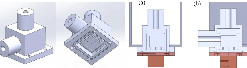
The impinging jet manifold shown in Figures 1 & 2 houses an inner plenum which is fed from the horizontally orientated inlet port. The liquid pressurizes the small volume within the plenum above the jet nozzle plate, forcing it through the 9 nozzles, here arranged in a square 3 x 3 array. The liquid subsequently impinges on the lower flat copper surface and then flows along the confining channel until expelled out at the four edges. The fluid then flows upward through gaps located between the main housing and the plenum and is then routed to an upper plenum. Here the fluid is forced upward out of the manifold through a vertically orientated port which connects the manifold to the flow loop.
The nozzle configuration is also presented in Figure 1 & 2Error! Reference source not found.. Nine 1 mm diameter jets with a jet to jet spacing of 5 mm and a jet to target spacing of 1 mm are employed for this study. Some preliminary data for the same jet configuration and a 2 mm spacing is also provided for comparison. Both manifolds were 3D printed using a laser sintering process from a nylon based material (PA2200). The melting temperature of the material is 150oC which meets the temperature requirements of the investigation. The manifold connects to Swagelok fittings through a 12 mm to 6 mm fixing with an 8mm thread. The inlet and outlet of the manifold were threaded subsequent to printing providing a watertight seal connection to and from the flow loop.
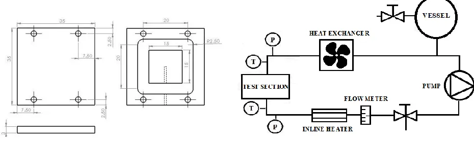
The copper heat transfer surface is shown in Figure 3. It is a 3 mm thick square piece of copper with an inner relief of 15mm x 15mm which acts as the effective heated area, with the outer area for sealing and mounting. The 15mm x 15mm lower protrusion is positioned atop the neck of a copper heater block (not shown) with an intermediate layer of thermal grease (see Figure 2). Two thermocouples within the neck of the copper block with 3mm spacing between them are used to determine the heat flux to the surface. There is also a thermocouple in the upper copper block in order to measure the surface temperature.
The main components of the flow loop are detailed in Figure 4. After exiting the test section, the fluid is cooled using a series of heat exchangers. A vessel is located after the heat exchangers to ensure that there is sufficient fluid available for the pump. The vessel is open to the atmosphere to negate build-up of pressure during testing and thus tests are carried out at nominally 1 bar. The pump is located after the heat exchanger along with a flow meter. The temperature of the fluid reaching the test section is regulated by an inline heater and PID controller which maintains the water at 93oC for these tests. The outlet was considered saturated when the outlet temperature remained constant despite increasing power input - typically occurred between 100.5 and 101.0oC Inlet and outlet pressures were also monitored.
Figure 1: Laser sintered 3D printed manifold design.
[image:3.612.82.514.273.393.2](a) (b)
Before the collection of data the rig was run at a high temperature for over an hour to remove trapped air from the system and degas the working fluid. A heat exchanger and chiller system was used to maintain the test section inlet temperature at the nominal set point of 93oC. The experiment began at low heat fluxes at the chosen flow rate and proceeded by incrementing the heat flux. The heat flux was controlled using a variable transformer that powered several cartridge heaters in the main heater block assembly (not shown). Increments were typically in the range of 50-100 W per data point. In between tests of varying flow rates the system was allowed to cool sufficiently to disable any active nucleation sites prior to the next test.
For each test point the system was allowed to reach steady state before data collection and this was characteristic by the surface temperature not varying by more than 0.2oC over a five minute period. Testing concluded when the system reached critical heat flux, a state of dangerously unsteady flow existed, the temperature of the copper block exceeded 600oC or the surface temperature exceeded 140oC. Data was collected using a National Instruments DAQ system and the temperatures were displayed in LabVIEW.
The primary purpose of the data reduction is to calculate the temperature of the surface and to determine the corresponding heat flux. The heat flux was determined using Fourier’s 1D conduction equation:
𝑞" = −𝑘𝐶𝑢𝑑𝑇
𝑑𝑥 (1)
The temperature gradient was determined by calculating the slope of the temperature along the neck of the main heater block via the two imbedded thermocouples. The surface temperature was calculated using the heat flux and the temperature that was measured 1.5 mm below the surface such that,
𝑇𝑠 = 𝑇3− 𝑞"𝐿
𝑘𝐶𝑢 (2) The conductivity of the copper varies with temperature and therefore a function was created to estimate the conductivity based on the average temperature within the copper neck. The effective heat transfer coefficient was determined by the following;
ℎ = 𝑞" 𝑇𝑤𝑎𝑙𝑙− 𝑇𝑠𝑎𝑡=
𝑞"
[image:4.612.75.540.125.265.2]∆𝑇𝑠𝑎𝑡 (3) Figure 4: Flow loop schematic.
The pumping power flux, first proposed by Kandlikar [2], was used to determine the performance of a heat transfer process normalised by the pumping power requirement:
𝑃 =𝑚̇ ∆𝑃
𝜌 (4)
The pumping power flux is then defined as the pumping power divided by the free flow area:
𝑃" = 𝑚̇ ∆𝑃
𝜌 𝐴𝑓𝑟𝑒𝑒 (5)
The free flow area was taken to be the total area of the jet nozzles. As the pumping flux and heat flux now have the same units, they can be used to define the coefficient of performance (COP):
𝐶𝑂𝑃 = 𝑞"
𝑃" (6) An uncertainty analysis was carried out in a similar manner to Kandlikar and Cooke [16]. The uncertainty associated with the variation of the conductivity of the copper was estimated to be 0.5%. Higher values are typically chosen when no function is employed to estimate the conductivity at a given operating temperature. The uncertainty of the distance between thermocouples was taken to be the uncertainty of the measurement equipment used, which was ±0.1mm. The thermocouples themselves were calibrated using a high precision oil bath and the uncertainties were taken to be ±0.2oC over the range of temperatures tested. The uncertainty of the surface temperature was found to be ±7% over the range of heat fluxes tested. The uncertainty of the heat flux was found to be ±23% and ±6% for low and high heat fluxes respectively, with commensurate uncertainty levels on the associated heat transfer coefficients. Although the uncertainties are quite high at lower heat fluxes, the study is more concerned with the performance at high heat fluxes where the uncertainties are acceptable. The uncertainty of the Reynolds number was determined to less than 5% at the highest flow rate and ±16% at the lowest flow rate tested.
3. Results and discussion
The effect of Reynolds number on heat transfer
3.1
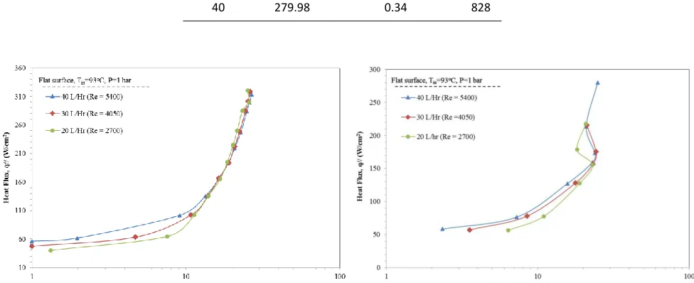
W/cm2, and it is noted that this is close to the experimental error of the investigation. The highest heat transfer coefficient reached during the 20 L/hr test was 112 kW/m2K at a heat flux of 280 W/cm2. The tests were stopped short of CHF due to instability in the flow rate, making data collection problematic and the experiments unsafe. It is likely that this signified the onset of CHF though for safety reasons CHF was
avoided until such time as correct shut down safety mechanisms could be put into place.
The effect of flow rate on pressure drop performance
3.2
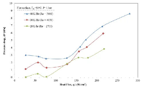
The pressure drop trends for the tests are given in Figure 7. For each case, the pressure drop remains fairly constant with increased flow rate for the single phase regimes, as would be expected. At ONB a significant increase in the pressure drop is then measured, highlighting the hydraulic penalty associated with convective boiling. Also as expected, the magnitude of both the single and two phase pressure drop increases with increased flow rate.
As mentioned, the maximum heat flux dissipation of 280 W/cm2 was achieved at 40 L/Hr, and this was achieved with a pressure drop of 8.6 kPa. A pressure drop of 5.9 kPa and 3.8 kPa was measured for 30
Figure 6: Comparison of heat transfer coefficients for flat copper surface with various flow rates.
[image:6.612.52.543.183.338.2]Figure 5: Comparison of heat transfer performance for flat copper surface with various flow rates.
[image:6.612.182.428.496.651.2]L/Hr and 20 L/Hr respectively with lower maximum heat flux dissipation rates. When comparing the COP at the 213 W/cm2 to 218 W/cm2 over the three flow rates, it is clear an optimal operating point with respect to efficiency would be that of using a flow rate of 20 L/Hr, as similar heat fluxes are dissipated at a disproportionately lower pressure drop when compared to 40 L/Hr test. Pumping flux, as suggested by Kandlikar to quantify the coefficient of performance [2], is tabulated in Table 2. Clearly, for commensurate heat flux levels, the lowest flow rate has associated with it a considerably lower pumping power flux. As a result, the COP is also significantly larger compared with the medium or large flow rates. This is due to the insensitivity of the heat transfer performance to Reynolds number (i.e. flow rate) coupled with the parabolic dependence of the pressure drop with flow rate. Hence, in certain instances it may in fact be more efficient to operate two phase impinging jet systems at the lowest possible flow rate because this reduces the pressure drop while maintaining the heat transfer performance.
The effect of nozzle to target spacing
3.3
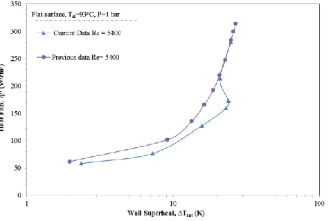
A manifold of the same design though with a nozzle to plate spacing of 2mm was previously tested using a similar rig set up and the results are presented in Figure 8 which can be compared with the boiling curves of the present study given in Figure 9. Figure 10 presents a clear comparison of the two cases whereby only the highest flow rate is shown for both jet to target spacing. As highlighted in the figures, the characteristics are similar for the single phase regimes. If anything, the smaller gap tends to cause a
Table 1: Pumping power flux.
Pumping power flux
Flow rate, Q (L/Hr)
Heat flux, q" (W/cm2)
Pumping power flux, P" (W/cm2)
COP
20 217.65 0.08 2838
30 215.72 0.17 1239
40 213.47 0.27 798
40 279.98 0.34 828
Figure 9: Boiling curves for various flow rates from current study with 1 mm jet to target spacing.
[image:7.612.65.553.380.579.2]moderate drop in the effectiveness of the single phase cooling, likely due to the increased confinement effects which tends to cause higher vertical channel velocities i.e. parallel to the impinging jets, which are known to wash out neighbouring jets when arranged in arrays and have a deleterious influence on the stagnation heat transfer. The figures also indicate that the higher cross flow channel velocities may also influence ONB, since it is noticed in Figure 10 that the higher spacing case transitions into the nucleate boiling regime at a noticeably lower heat flux and does not experience the superheat overshoot of the narrower channel. Interestingly, once ONB occurs for the smaller 1 mm channel, its boiling curve merges with that of the 2mm channel providing evidence that fully developed boiling heat transfer is not sensitive
to jet to target spacing or flow rate.
4. Conclusions
An impinging water jet array has been investigated over a range of flow rates and imposed surface heat fluxes. The results show that utilising jet impingement boiling can dissipate high fluxes, in this case approaching 300 W/cm2, and provide high heat transfer coefficients at reasonable pressure drops. The main conclusions of this study are as follows:
1. At low heat fluxes the single phase heat transfer performance depends on Reynolds number 2. For the high level of confinement in this study, a superheat overshoot occurs. Subsequent to ONB
the boiling curves merge in the fully developed boiling regime showing insensitivity to flow rate. 3. The pressure drop is independent of heat flux for single phase flow. Once significant boiling
occurs, the pressure drop increases monotonically with imposed heat flux and flow rate.
4. Owing to the insensitivity of the heat transfer to flow rate during fully developed boiling, the coefficient of performance of jet impingement boiling in the fully developed boiling regime deteriorates with increases flow rate due to the increase in pumping power flux.
[image:8.612.190.429.226.386.2]5. Small nozzle to plate spacing could potentially delay ONB and have a detrimental influence on the heat transfer compared with earlier tests with a higher gap. However, jet to target spacing does not appear to influence the heat transfer in the fully developed boiling regime.
5. Nomenclature
A = area (m2)
h = heat transfer coefficient (W/m2K)
kCu = thermal conductivity of copper (W/mK) L = distance from chip thermocouple to surface, mm
𝑚̇ = mass flow rate, kg/s P = pumping power
ΔP = Pressure difference, Pa q” = heat flux, W/m2
S = Nozzle to plate distance
T = Temperature, oC
Greek Symbols:
ΔTsat = wall superheat, K
ΔTsub = fluid subcooling, K
Δx = distance between thermocouples, mm ρ = density, kg/m3
Superscript: s = surface
6. Bibliography
1. Kandlikar, S.G., et al., Heat transfer in microchannels—2012 status and research needs. Journal of Heat Transfer, 2013. 135(9): p. 091001.
2. Steinke, M.E. and S.G. Kandlikar. Single-phase liquid heat transfer in plain and enhanced microchannels. in ASME 4th International Conference on Nanochannels, Microchannels, and Minichannels. 2006. American Society of Mechanical Engineers.
3. Kandlikar, S.G., et al., Enhanced Flow Boiling Over Open Microchannels With Uniform and Tapered Gap Manifolds. Journal of Heat Transfer, 2013. 135(6): p. 061401.
4. Zhao, Z., Y. Peles, and M.K. Jensen, Water jet impingement boiling from structured-porous surfaces. International Journal of Heat and Mass Transfer, 2013. 63(0): p. 445-453.
5. Wolf, D.H., F.P. Incropera, and R. Viskanta, Jet Impingement Boiling, in Advances in Heat Transfer, P.H. James and F.I. Thomas, Editors. 1993, Elsevier. p. 1-132.
6. Wolf, D.H., F.P. Incropera, and R. Viskanta, Local jet impingement boiling heat transfer. International Journal of Heat and Mass Transfer, 1996. 39(7): p. 1395-1406.
7. KATTO, Y. and M. KUNIHIRO, Study of the mechanism of burn-out in boiling system of high burn-out heat flux. Bulletin of JSME, 1973. 16(99): p. 1357-1366.
8. Elkassabgi, Y. and J. Lienhard, Influences of subcooling on burnout of horizontal cylindrical heaters. Journal of heat transfer, 1988. 110(2): p. 479-486.
9. Hong, Y., C. Ammerman, and S. You. Effects of length scale, subcooling, and dissolved gas content on the pool boiling critical heat flux of cylindrical heaters. in Heat Transfer Conference. 1998.
10. Khanikar, V., I. Mudawar, and T. Fisher, Effects of carbon nanotube coating on flow boiling in a micro-channel. International Journal of Heat and Mass Transfer, 2009. 52(15-16): p. 3805-17.
11. Cardenas, R. and V. Narayanan, Submerged jet impingement boiling of water under subatmospheric conditions. Journal of Heat Transfer, 2012. 134(2): p. 020909.
12. Zhou, D., C. Ma, and J. Yu, Boiling hysteresis of impinging circular submerged jets with highly wetting liquids. International journal of heat and fluid flow, 2004. 25(1): p. 81-90.
13. Ndao, S., Y. Peles, and M.K. Jensen, Experimental investigation of flow boiling heat transfer of jet impingement on smooth and micro structured surfaces. International Journal of Heat and Mass Transfer, 2012. 55(19): p. 5093-5101.
14. Rau, M.J. and S.V. Garimella, Local two-phase heat transfer from arrays of confined and submerged impinging jets. International Journal of Heat and Mass Transfer, 2013. 67(0): p. 487-498.
15. Rau, M.J. and S.V. Garimella, Confined jet impingement with boiling on a variety of enhanced surfaces. Journal of Heat Transfer, 2014. 136(10): p. 101503.
16. Cooke, D. and S.G. Kandlikar, Pool boiling heat transfer and bubble dynamics over plain and enhanced microchannels. Journal of Heat Transfer, 2011. 133(5): p. 052902.