International Journal of Emerging Technology and Advanced Engineering
Website: www.ijetae.com (ISSN 2250-2459,ISO 9001:2008 Certified Journal, Volume 2, Issue 12, December 2012)
259
Power System Control Through STATCOM and UPFC
(FACTS)
Vaishali P Kuralkar
1, Prof. Sulabha U Kulkarni
21
M. Tech Student, 2Associate Professor, Electrical Engineering Department, BVUCOEP, Pune, India
Abstract— FACTS devices have the capability to control voltage, impedance and the phase angle in transmission circuit and hence control the power flow. Among the
converter based FACTS devices Static Synchronous
Compensator (STATCOM) and Unified Power Flow Controller (UPFC) are considered in this paper. Static and dynamic analysis of the standard 5 bus system is done in MATLAB .The result of network with and without using UPFC and STATCOM are compared in terms of active and reactive power flows in the line and at the bus to analyze the performance of the devices Iinjected voltage, Injected phase , phase distortion are also shown graphically .
Keywords— FACTS, Newton Raphson, Power flow,
STATCOM, UPFC
I. INTRODUCTION
The deregulation of power utilities and the power oscillations in the interconnected grids have created many obstructions for the generation and also for the installation of new transmission lines. As power transfer grows the system becomes more complex, less secure and large power flows with inadequate control, excessive reactive power and large dynamic swings leading to inefficient utilization of interconnected grid. The ability of the transmission system to transmit power becomes impaired by one or more of the following steady state and dynamic limitations: (a) angular stability, (b) voltage magnitude, (c) thermal limits, (d) transient stability, and (e) dynamic stability. [3]
The technology such as flexible ac transmission system
(FACTS), can help to find the solution. Facts devices provide voltage support at critical buses in the
system (shunt connected controllers) and regulate power flow in critical lines (with series connected controllers) [6]. The need for these power flow controllers capable of increasing transmission capability and controlling power flows is increasing.[1]
The universal and most flexible FACTS device is the Unified Power Flow Controller (UPFC). UPFC is the combination of three compensators’ characteristic; i.e. impedance, voltage magnitude and phase angle, that are able to produce a more complete compensation.[2] This device is actually a combination of two FACTs device which are STATCOM (Static Synchronous Compensator) and SSSC (Static Series Synchronous Compensator). SSSC is used to add controlled voltage magnitude and phase angle in series with the line, while shunt converter STATCOM is used to provide reactive power to the ac system, beside that, it will provide the dc power required for both inverter. The reactive power can be compensated either by improving the receiving voltage or by reducing the line reactance.
UPFC should be installed to control the voltage, as well as to control the active and reactive power flow through the transmission line .This paper presents the power flow control for the standard five bus system (static and dynamic analysis) with and without the FACTS devices.
II. POWER FLOW CONTROL
The power transmission line can be represented by a two-bus system ―k‖ and ―m‖ in ordinary form. The active power transmitted betweens bus nodes k and m is given by:
P = V m * V k Sin (δk – δm)... (1) X
Where V m and V k are the voltages at the nodes, (δk - δm) the angle between the voltages and X the line impedance. The power flow can be controlled by altering the voltages at a node, the impedance between the nodes and the angle between the end voltages [5]. The reactive power is given by:
International Journal of Emerging Technology and Advanced Engineering
Website: www.ijetae.com (ISSN 2250-2459,ISO 9001:2008 Certified Journal, Volume 2, Issue 12, December 2012)
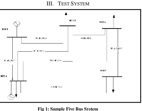
260 III. TEST SYSTEM
Fig 1: Sample Five Bus System
The standard five bus system is taken for the analysis. The system has five buses, two generator, and seven transmission lines .The system is studied for the following three cases:
1) Without any FACTS devices in the system 2) With STATCOM in the system
3) With UPFC in the system
A. CASE I
[image:2.612.50.297.135.329.2]Initially the system is analysed without any FACTS devices.
Table 1
BUS RESULTS WITHOUT FACTS DEVICES
Table 2
LINE RESULTS WITHOUT FACTS DEVICES
LINE NO P (p.u) Q(p.u)
01 0.1340 1.2118
02 0.1522 0.2122
03 -2.2139 0.5220
04 -2.1820 0.3555
05 -6.2785 2.9302
06 -22.9455 10.9021
07 -3.5902 5.5066
In the system the reactive power load is maximum in the transmission line no 6 which is connecting the bus 2 and bus 3 as shown in Fig.1. The active power in line 6 is -22.9455 p.u and the reactive power is 10.9021 p.u . To improve the performance of the system the Facts device STATCOM is included at the bus 2 and UPFC in bus 2 and bus 3.
B. CASE II
The shunt connected static compensator was developed as an advanced static VAR compensator where a voltage source converter (VSC) is used instead of the controllable reactors and switched capacitors [6]. The STATCOM is included in bus 2 of the sample system to maintain the nodal voltage at 1 p.u.
STATCOM DATA
Initial source voltage magnitude: 1 p.u [7]
[image:2.612.320.563.156.286.2]Phase degrees: 0 degrees
Table 3
BUS RESULTS WITH STATCOM AT BUS 2
BUS _ NO 01 02 03 04 05
V_MAG: 1.06 1.013 0.9946 1.002 0.9753
V _ ANG 0 -4.7529 -4.8236 -2.0365 -5.8268
BUS _ NO 01 02 03 04 05
V_MAG: 1.06 0.9871 0.9836 1.01 0.9721
International Journal of Emerging Technology and Advanced Engineering
Website: www.ijetae.com (ISSN 2250-2459,ISO 9001:2008 Certified Journal, Volume 2, Issue 12, December 2012)
[image:3.612.59.280.156.287.2]261
Table 4
LINE RESULTS WITH STATCOM AT BUS 2
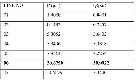
LINE NO P (p.u) Q(p.u)
01 1.4068 0.8461
02 0.1492 0.2457
03 5.3052 5.6402
04 5.3496 5.3818
05 7.8564 7.2254
06 30.6750 30.9922
07 -3.6099 5.3440
The power flow indicates that STATCOM generates reactive power 30.9922 (p.u ) to maintain the bus voltage at bus 2 at 1 p.u .Convergence is obtained in four iterations with tolerance of 10 -12. It is very clear from the comparison of Table I and III ,that the nodal voltage is maintained at 1.013 at bus 2 by STATCOM and the phase angle is also improved to -4.7529(degrees ) from -0.464(degrees) . The active power is also increased from -22.9455 (p.u) to 30.6750 (p.u) .
C. CASE III
The five bus system is modified to include one UPFC to compensate the transmission line linking bus 2 and bus 3. The UPFC shunt converter is set to regulate the nodal voltage magnitude at bus 2 at 1 p.u.
UPFC DATA: [7]
The starting values of UPFC shunt converter are:
Voltage magnitude: 1 p.u
Phase degrees: 0 degrees
For series converter: voltage magnitude: 0.04 p.u
Phase degrees: 87.3 degrees
Table 5
BUS RESULTS WITH UPFC BETWEEN BUS 2 AND 3
BUS _ NO
01 02 03 04 05
V_MAG: 1.06 0.9998 0.9901 1.0037 0.9746
V _ ANG 0 -0.92985 -1.9276 -4.1288 -11.564
Table 6
LINE RESULTS WITH UPFC BETWEEN BUS 2 AND 3
UPFC increases the amount of reactive power supplied at the bus 2 to 35.7096 (p.u) which very high as compared to 30.9922 (p.u) with STATCOM and10.9021 (p.u) without any FACTS devices. There is increase in the active power also due to the demand of the UPFC series converter.
IV. DYNAMIC ANALYSIS OF THE SYSTEM
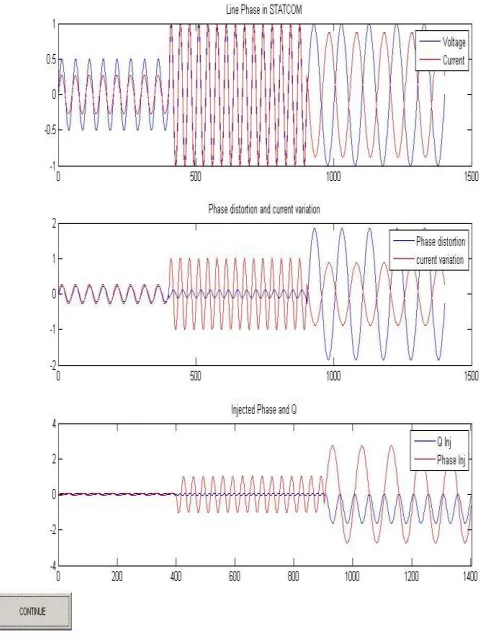
The same five bus system is tested for dynamic load variations. STATCOM is included in bus 2 and UPFC in bus 2 and 3 .Load is taken as a function of time and then the system is analysed .The X- Axis of the graph shows the time and the Y – Axis the respective parameter. Fig 2 and Fig 3 show the following three results with STATCOM and UPFC respectively:
1) Voltage and Current injected graphs 2) Phase distortion and Current variations 3) Reactive power injected and phase injected
LINE NO P (p.u) Q(p.u)
01 0.2719 1.0112
02 0.3028 0.2468
03 -4.0745 2.0098
04 -4.0005 1.8088
05 -7.5400 9.9569
06 -30.1488 35.7096
International Journal of Emerging Technology and Advanced Engineering
Website: www.ijetae.com (ISSN 2250-2459,ISO 9001:2008 Certified Journal, Volume 2, Issue 12, December 2012)
[image:4.612.54.296.150.471.2]262
Fig 2: Performance of the system with STATCOM at bus 2
Fig 2 clearly shows that due to the STATCOM the voltage injected and the reactive power is greatly improved. The phase distortion is also reduced significantly.
Fig 3: Performance of the system with UPFC at bus 2 and bus 3
UPFC has delivered much better results as compared to STATCOM in terms of voltage injected , phase angle , active and reactive power.
It is clear from the dynamic analysis Fig.2 and Fig.3 that STATCOM and UPFC increase the performance of the system .
[image:4.612.329.564.151.453.2]International Journal of Emerging Technology and Advanced Engineering
Website: www.ijetae.com (ISSN 2250-2459,ISO 9001:2008 Certified Journal, Volume 2, Issue 12, December 2012)
263
V. CONCLUSION
This paper has presented the simulation methods required for study of the steady state as well as dynamic operation of electrical systems with FACTS devices UPFC and STATCOM.
The power flow for the five bus system was analysed with and without FACTS devices. The power flow indicates that there is nearly 2.6 % increase in the reactive power absorption compared with the base case when STATCOM is included in bus 2. The largest reactive power flow takes place in the transmission line connecting bus 2 to bus 3, which is 30.9922 p.u. The direction of reactive power flow remains unchanged.
The sample 5 bus network is modified to include one UPFC to compensate the transmission line no. 6 linking bus 2 and bus 3. The UPFC shunt controller is set to regulate the nodal voltage magnitude at bus 2 at 1 p.u. There is large amount of increase in the active power as well as the reactive power. The steady state models of STATCOM and UPFC are analysed and evaluated in Newton-Raphson algorithm. Both, the static and the dynamic analysis show that UPFC is able to control not only the voltage but also the impedance and phase angle which affect the power flow in the transmission line.
REFERENCES
[1] Edvina Uzunovic Claudio, A. Ca~nizares John Reeve , EMTP Studies of UPFC Power Oscillation Damping North American Power Symposium (NAPS), San Luis Obispo, California, October 1999.
[2] Nashiren.F. Mailah , Senan M. Bashi , Single Phase Unified Power Flow Controller (UPFC): Simulation and Construction. European Journal of Scientific Research ISSN 1450-216X Vol.30 No.4 (2009), pp.677-684
[3] Pavlos S. Georgilakis1,a and Peter G. Vernados, Flexible AC Transmission System Controllers: An Evaluation Materials Science Forum Vol. 670 (2011) pp 399-406
[4] Alireza Seifi, Sasan Gholami and Amin Shabanpour , Power Flow Study and Comparison of FACTS: Series (SSSC), Shunt (STATCOM), and Shunt-Series (UPFC). The Pacific Journal of Science and Technology
[5] Narain G. Hingorani and Laszlo Gyugyi, Understanding FACTS, Wiley India publication.
[6] K.R Padiyar FACTS Controllers in Power Transmission and Distribution