International Journal of Emerging Technology and Advanced Engineering
Website: www.ijetae.com (ISSN 2250-2459, ISO 9001:2008 Certified Journal, Volume 3, Issue 3, March 2013)
515
Design Of Low Power Parallel FIR Digital Filter Using
Floating - Point Multiplier
Neelam Gathibandhe
1, Pradnya Zode
2An Autonomous Institution Affiliated to RTMNU Yashwantrao Chavhan College of Engg, Nagpur; Department of Electronics Engineering.
An Autonomous Institution Affiliated to RTMNU Yashwantrao Chavhan College of Engg, Nagpur;
Plot k-13, Himalaya Vishva, Nagpur Road Wardha-442001.
Abstract—The Finite impulse response (FIR) filter is used as a fundamental processing element in any Digital signal processing (DSP) system. This paper describe the technique of Algorithemic strength reduction which leads to a reduction in hardware complexity by exploiting substructure sharing(by reducing the number of multiplications and additions). This transformation is basically implemented for the reduction in silicon area or power consumption of Very large scale integration (VLSI) design or iteration period in a programmable digital signal processing (DSP) implementation. Here we will focus on implementation based on Field Programmable Gate Array (FPGAs) because many of the approaches are applicable to ASIC or custom VLSI application. The sub-modules has been written in Verilog HDL and they are synthesized and simulated using the Xilinx ISE targeted on Field programmable Gate Array (FPGA).
Keywords— CLA, CSGCs, CSK, DSP, ETA, FIR, FPGA, LSB, MSB, RCA, TE, VLSI .
I. INTRODUCTION
FIR filters are one of two primary types of digital filters used in Digital signal Processing (DSP) applications. Main approach is to implement high throughput FIR filter.Multiplier block reduction has attempted to minimize various cost functions such as number of adders and multipliers block area by sub expression elimination. Attention has been paid to identify ways to reduce power consumption of high throughput FIR implementation based on FPGA. Implementations based on FPGA hardware are better suited because of the likely need for frequent modifications. To increase the effective throughput of original filter or to reduce the power consumption of original filter parallel or block processing has been applied to digital FIR filter. In many design situation the overhead hardware incurred by parallel processing cannot be tolerated due to design area limitation.
Therefore it is beneficial to realize parallel FIR filtering structure that consume less area than the traditional one. Sub modules used will be Floating point multiplier and Error tolerant adder (ETA). ETA includes sub modules i.e. modified XOR gate and Ripple Carry Adder. Ripple Carry Adder is used because it requires less hardware. ETA cause less power consumption due to the elimination of carry propogation to a large extent.
A. Applications
FIR filters are used as a fundamental processing element in any DSP system. FIR filters are used in DSP applications ranging from video and image processing to wireless communications[2]. In the application of video processing, the FIR filter circuit must be able to operate at high frequencies, while in other applications, such as cellular telephony, the FIR filter circuit must be a low-power circuit, capable of operating at moderate frequencies.
B. FIR Filters
International Journal of Emerging Technology and Advanced Engineering
Website: www.ijetae.com (ISSN 2250-2459, ISO 9001:2008 Certified Journal, Volume 3, Issue 3, March 2013)
516 Advantages of FIR filters compared to IIR filters :
They can be easily design to the ―linear phase‖. Linear phase delay the input signal but not distort its phase.
They are simple to implement. In most DSP microprocessors, the FIR calculation can be done by looping a single instruction.
They are suited to multirate applications, means either ―decimation‖ (reducing the sampling rate), ―interpolation‖(increasing the sampling rate ), or both. Whether decimating or interpolating, the use of FIR filters allows some of the calculation to be omitted, thus providing an important computational efficiency. In contrast, if IIR filters are used, each output must be individually calculated, even if that will discarded (so the feedback will be incorporated into the filter).
They have desirable numeric properties. In practice, all DSP filters must be implemented using finite-precision arithmetic, that is, a limited number of bits. The use of finite-precision arithmetic in IIR filters can cause significant problem due to the use of feedback, but FIR filters without feedback can usually be implemented using fewer bits, and the designer has fewer practical problems to solve related to non-ideal arithmetic.
FIR filters can be implemented using fractional arithmetic. Unlike the IIR filters, it is always possible to implement a FIR filters using coefficients with magnitude less than 1.0. (The overall gain of the FIR filter can be adjusted at its output, if desired.) This is an important consideration when using Fixed-point DSP’s, because it makes the implementation much simpler.
C. Error Tolerant Adder (ETA)
Truncation and rounding off errors in adders has become unavoidable in modern VLSI technology. Therefore a new novel adder has been proposed called as the Error Tolerant Adder (ETA) to attain low power consumption and high speed performance in DSP system. In conventional adders circuit delay is mainly due to the carry propagation chain along the critical path from least significant bit (LSB) to most significant bit (MSB). If carry propagation is eliminated by the technique proposed, a great improvement in speed performance and power consumption is achieved [3][4].
D. Floating – Point Multiplier
IEEE Standard 754 Floating Point Numbers :
Floating point describes a method of representing real numbers in a way that can support a wide range of values.
The base for scaling is normally 2,10,16. The representation is exactly have the form:
Significant digits × base ^ (exponent).
The term floating point refers to the fact that the radix point (decimal point or in computers, binary point) can ―float‖; that is, it can be placed anywhere relative to the significant digits of the number. The advantage of floating-point representation over fixed-point and integer representation is that it can support a much wide range of values eg. Fixed-point representation has seven decimal digits with two decimal places can represent the number 34565.67 , 145.12 , 1.45 and so on, whereas a floating-point representation (such as IEEE 754decimal 32 format) with seven decimal digits could in addition represent 1.324765, 234516.7, 0.00003455687, 4327651000000000, and so on. The floating-point format needs slightly more storage (in order to encode the position of the radix point). So when stored in the same space, floating-point numbers achieve their greater range at the expense of precision.
II. FINITE IMPULSE RESPONSE FILTER
A . Traditional 4 - Parallel FIR Filter Implementation
The N-tap FIR filter in Z domain is given by
∑ ∑
Traditional 4- parallel FIR filter Equations[7]
International Journal of Emerging Technology and Advanced Engineering
Website: www.ijetae.com (ISSN 2250-2459, ISO 9001:2008 Certified Journal, Volume 3, Issue 3, March 2013)
[image:3.612.62.273.139.461.2]517 Fig 1.Traditional 4-parallel FIR Filter [7]
B . Reduced Complexity Low Power 4 - Parallel FIR Filter Implemantation
The N-tap FIR filter in Z domain is given by
∑
∑
)
Reduced complexity 4 parallel FIR filter equation[7]
[( )( )
]
( )( )
(
)( )
( )
( )
( )( )
( )
( )
( )( )
( )( )
[( )( ) ]
[( )( )
]
International Journal of Emerging Technology and Advanced Engineering
Website: www.ijetae.com (ISSN 2250-2459, ISO 9001:2008 Certified Journal, Volume 3, Issue 3, March 2013)
518 Fig2. Reduced complexity 4-parallel FIR Filter [7]
III. PROPOSED ADDITION ARITHEMATIC OF ETA
[image:4.612.329.555.223.447.2]Input operand are split into two parts : Accurate part and Inaccurate part. Length of each part need not to be equal[3][4].
Fig 3. Proposed Addition Arithematic [3][4]
A. Accurate Part
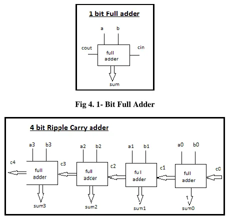
In accurate part normal addition method is applied from right to left i.e. from LSB to MSB to preserve its correctness since the higher order bits play an important role than lower order bits. RCA is choosen for accurate part of circuit since it is simplest one most power saving and requires less hardware circuitary[3][4].
Fig 4. 1- Bit Full Adder
Fig 5. 4-bit Ripple Carry Adder
B. Inaccurate Part
In this part no carry signal will be generated at any bit position therefore propagation path will not exist. It is divided into two blocks: Carry free addition block and Control block. For this a special strategy is adapted
Carry free addition block check every bit position from MSB to LSB.
If both inputs are ―0‖ or different, normal XOR operation is performed and operation proceed to next bit position.
[image:4.612.60.277.566.665.2]International Journal of Emerging Technology and Advanced Engineering
Website: www.ijetae.com (ISSN 2250-2459, ISO 9001:2008 Certified Journal, Volume 3, Issue 3, March 2013)
[image:5.612.132.207.136.252.2]519 Fig 6. Control signal generating cell [3][4]
When clti = 0, M1 and M2 turn on, M3 turn off which force circuit to operate in normal XOR mode
[image:5.612.335.553.137.288.2]When clti = 1, M1 and M2 turn off, M3 turn on which connect output node to VDD therefore sum bit set to ―1‖[3][4].
Fig 7. 1-Bit Modified XOR gate with CSGCs [3][4]
[image:5.612.108.231.333.506.2]Fig 8. 4-Bit Modified Xor gate
Fig 9.46-Bit Error tolerant adder
C. Accuracy Calculation
The above addition should actually yield 85227 if normal arithematic has been applied. The total error generated can be computed as
TOTAL ERROR (TE) = |Bc - Be|
Where, Be is the result obtain from ETA adder and Bc denotes correct result
TE = |85227 - 85215| = 12
ACCURACY = (1 – TE/Bc) × 100 = (1 – 12/85227 ) = 99.98% (accuracy of adder with respect to two input operand).
[image:5.612.71.266.524.684.2]International Journal of Emerging Technology and Advanced Engineering
Website: www.ijetae.com (ISSN 2250-2459, ISO 9001:2008 Certified Journal, Volume 3, Issue 3, March 2013)
520
IV. FLOATING –POINT MULTIPLIER DESIDN
[image:6.612.332.553.141.412.2]A . Simplified Floating – Point Multiplication Flow Chart
[image:6.612.63.273.169.644.2]Fig 10.Simplified floating point multiplication chart
Fig 11.Floating point multiplier design[5]
B . Floating – Point Multiplication Is Carried Out In Three Parts
In the first part, sign of product is determine by performing XOR operation on the sign bits of the two operands.
In the second part, the exponent bits of the operands are passed to an adder stage and a bias of 127 is substracted from the obtained output. The addition and bias subtraction operation are both implemented using ETA. Overflow and underflow conditions are indicated by setting the respective flags.
International Journal of Emerging Technology and Advanced Engineering
Website: www.ijetae.com (ISSN 2250-2459, ISO 9001:2008 Certified Journal, Volume 3, Issue 3, March 2013)
521
V. SIMULATION RESULTS
A . RTL View of Ripple Carry Adder
B . 26 Bit Ripple Carry Adder
C . 20 Bit Modified Xor Gate
D . 48 Bit Error Tolerant Adder
VI. CONCLUSION
Adder structure is applicable to general purpose design , with a few exceptions.The need for instant response and increasingly huge data sets, the adder should be large and fast. The traditional Ripple Carry Adder (RCA) is therefore no longer suitable for large adders because of its low speed performance but it require less hardware. The Carry Skip Adder (CSK) reduce the carry propagation time by skipping over groups of consecutive adder stages. CSK is usually comparable in speed to the Carry Lookahead Adder (CLA), but requires less chip area and consumes less power compared to CLA. Carry-Select Adder consist of two Ripple Carry Adders and one Multiplexer. The two adders are used to calculate addition twice; one addition is computed assuming carry input ―1‖ and the other as ―0‖, the correct output is then selected upon the arrival of carry-in and CLA have been developed. The CLA Adder has lower delay but requires much more complex circuitry in achieving its performance. However, there is always trade-offs between speed and power. The ETA design can be a potential solution to this problem. But by sacrificing some accuracy, the ETA can attain great improvement in both the power consumption and speed performance.
REFERENCES
[1 ] Chao Cheng and Keshab K. Parhi, ―Low- Cost Parallel FIR Filter Structure with 2-Stage Parallelism,‖ IEEE TRANSACTIONS ON CIRCUITS AND SYSTEMS—I: REGULAR PAPER, VOL . 54, NO . 2, FEBRUARY 2007.
[2 ] Yujie Liu, Wenjiang Pei and Zehan Chen, ―DESIGN AND IMPLEMENTATION OF REDUCED COMPLEXITY FIR FILTER IN COMMUNICATION SYSTEM,‖ IEEE Int . Conference Neural Networks & Signal Processing Zhenjiang, China, June 8~10, 2008. [3 ] Ning Zhu, Wang Ling Goh, Weija Zhang, Kiat Seng Yeo, and
International Journal of Emerging Technology and Advanced Engineering
Website: www.ijetae.com (ISSN 2250-2459, ISO 9001:2008 Certified Journal, Volume 3, Issue 3, March 2013)
522
[4 ] Ratna Deepthi Kethineni and L.Srinivas, ―High Speed Truncation Error – Tolerant Adder‖ International Journal of Engineering Research & Technology (IJERT) Vol.1 Issue 5, July-2012. [5 ] Anna Jain, Baisakhy Dash, Ajit Kumar Panda, Muchharla Suresh,
―FPGA Design of a Fast 32-bit Floating Point Multiplier Unit‖ IEEE Int. Conference Devices, Circuit and systems (ICDCS) 15-16 March 2012.
[6 ] Mark A. Erle, Brian J. Hickmann and Michael J. Schulte, ―Decimal Floating-Point Multiplication‖ IEEE TRANSACTION ON COMPUTERS, VOL. X, NO. Y, MONTH 2008.
![Fig 1.Traditional 4-parallel FIR Filter [7]](https://thumb-us.123doks.com/thumbv2/123dok_us/8731839.887129/3.612.62.273.139.461/fig-traditional-parallel-fir-filter.webp)
![Fig 6. Control signal generating cell [3][4]](https://thumb-us.123doks.com/thumbv2/123dok_us/8731839.887129/5.612.71.266.524.684/fig-control-signal-generating-cell.webp)
![Fig 11.Floating point multiplier design[5]](https://thumb-us.123doks.com/thumbv2/123dok_us/8731839.887129/6.612.63.273.169.644/fig-floating-point-multiplier-design.webp)
