© 2017, IRJET | Impact Factor value: 5.181 | ISO 9001:2008 Certified Journal | Page 587
CFD ANALYSIS ON AN ATMOSPHERIC RE-ENTRY MODULE
SHAFEEQUE A P
Assistant Professor, Department of Mechanical Engineering, Cochin College of Engineering and Technology,
Valanchery, Malappuram, Kerala, India
---***---Abstract -
Atmospheric re-entry refers to the movement of human made objects as they enter the atmosphere of a planet from outer space. Re-entry modules are blunt-bodies designed to withstand high heating loads experienced during entry into the atmosphere. Here conduct an external flow analysis on atmospheric re-entering vehicle called Apollo AS-202 developed by NASA. Computational fluid dynamics is used to obtain the flow field that develops around re-entry capsules. To evaluate the heat flux variation, velocity profile, temperature variation and pressure distribution at various locations of the capsules are presented. By specifying the appropriate boundary conditions, one can modify the speed and Angle of Attack (AoA) of the re-entry vehicle. It accounts for changes in temperature, density, and pressure of the surrounding atmosphere, and even includes viscous effects and shock waves. The analysis is carried out for turbulent flow and standard flow properties available for re-entry capsules in the literature using Navier-Stokes solver for different Mach numbers.Key Words
:
Re-entry vehicles, Atmospheric re-entry,
Aerodynamic Heating, Thermal protection system, Hypersonic Flow, Angle of attack, CFD, Heat fluxes.
1. INTRODUCTION
Re-entry capsules are used for space exploration applications due to their ability to withstand high heating loads during the re-entry phase. A re-entry capsule consists of a blunt fore body, followed by a conical after body with straight or rounded base [1]. A bow shock forms ahead of the vehicle to slow down the hypersonic flow. Apart from the blunt-shaped nose, the most recent re-entry vehicles are equipped with ablative Thermal Protection Systems (TPS) to avoid possible damage of the capsule and insulate the vehicles content.
In re-entry vehicles, during re-entry phase, the thermal loads play a major part. A re-entry capsule encounters a high temperature and chemically reacting flow during the re-entry phase[2]. Computational Fluid Dynamics is extensively
used to simulate these flows, as high enthalpy and low density associated with the flight conditions are difficult to reproduce in wind tunnels or shock tunnels at each re-entry trajectory point. Wind and shock tunnel tests are difficult and are costly to conduct at high enthalpy conditions. CFD is a much more economical approach for studying such flows. Therefore CFD is extensively used as an analysis tool in the design of hypersonic vehicles. CFD is also used as a research tool to understand the complicated hypersonic effects.
Thermal analysis plays an important role in the design of atmospheric re-entry vehicles, which are subjected to severe aerodynamic heating. However, the thermal analysis is subject to a number of uncertainties. There can also be high uncertainty in the prediction of aerodynamic heat flux, due to factors such as scatter in the re-entry trajectory and highly complex phenomena that are difficult to analyze [3].
When a capsule reenters an atmospheric environment, a strong shock wave is formed in front of it. Behind the shock wave, a shock layer with very high temperature appears where a high enthalpy fluid flows around a capsule, resulting in a severe heating environment. Moreover, in an environment where the capsule velocity exceeds 8 km/s such as a super-orbit re-entry, there appear complicated phenomena accompanied by the radiation and/or the influence of turbulence [4].
© 2017, IRJET | Impact Factor value: 5.181 | ISO 9001:2008 Certified Journal | Page 588
1.1 Aerodynamic Heating
Atmospheric re-entry vehicles are subjected to aerodynamic heating during re-entry phase of their operation. Aerodynamic heating is the heating of a solid body produced by the passage of fluid over the body. It is a form of forced convection in that the flow field is created by forces beyond those associated with the thermal processes. This process generates heat and consequently all external surfaces of the vehicle are heated.
Due to aerodynamic heating external surfaces of the re-entry vehicle gets heated. Thermal Protection Systems are necessary in order to protect the internal structure of the vehicle from the elevated heat fluxes occurring on the external surfaces. The design of a Thermal Protection System is based on the principle that the energy released by the aerodynamic heating must be absorbed or rejected by the Thermal Protection System.
2. METHODOLOGY
A CFD analysis on a launch vehicle can be broken down into few parts: (i). Creating a required model of re-entry vehicle in a computer program, (ii). Import the geometry into a meshing program, such as HYPERMESH, (iii). Analyse the meshed geometry in a CFD program by setting the design parameters and environmental conditions, (iv). Post-processing the output and evaluate the results.
2.1 AS-202 Flight Data
The flight data used for assessment/comparison of heat flux data on the capsule were taken from the AS-202 flight test which was performed as part of the Apollo program. Once the Apollo entry vehicle design was determined, two flight tests of the actual Command Module (AS-201 and AS-202) were conducted at super orbital entry velocities resulting from suborbital boosted trajectories with an intentional skip maneuver. Although AS-201 did not carry an on board inertial measurement unit (IMU), one was carried during the AS-202 flight, which enabled a reconstruction of the flight trajectory and vehicle orientation as a function of time. Figs. 1-3 and tables 1 and 2 are taken from Louis M.G.Walpotet.al[5][6][7].
Fig.1 Schematic drawing of the outer mould line of AS-202 capsule
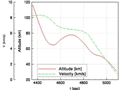
The afterbody heating environment for the Apollo Command Module shape as measured on the AS-202 mission is used as basis for comparison between CFD results and flight data.Fig.1 shows the outer mould line of the AS-202 as modeled for the CFD analyses. The re-entry trajectory of AS-202 in terms of velocity and altitude vs. time is shown in Fig.2.The points in time and the related freestream conditions used for comparison to flight data are tabulated in Table1. The small side slip angle has been neglected in the current simulations.
Fig.2 Altitude and velocity as a function of time from launch for AS-202.
Table 1 As-202 Trajectory Points And Freestream Conditions
[image:2.595.327.561.54.260.2] [image:2.595.337.529.418.561.2] [image:2.595.313.572.636.725.2]© 2017, IRJET | Impact Factor value: 5.181 | ISO 9001:2008 Certified Journal | Page 589 consisted of 23 surface-mounted calorimeters and 24
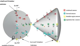
pressure transducers. Both flights were highly successful, with 16 of the calorimeters returning useful data on AS-201 and 19 on AS-202.Table 2 contains the exact coordinates of each calorimeter position. The afterbody heating rates for AS-201 were much higher than those for AS-202 because of the steeper entry angle (maximum heating rate of 25 vs 9 W/cm2) [8].
Fig.3 Locations of calorimeters on AS202 conical after body. Orange symbols indicate inoperative instruments.
[image:3.595.312.558.58.212.2]Letters correspond to the ID.
Table 2 Afterbody calorimeter locations for AS-202.
2.2 Geometrical Modelling
The Apollo Command Module essentially consisted of a spherical section forebody and a 330 conical afterbody. The CM capsule was a 330 half-angle cone with the blunt after heat shield formed from a segment of a sphere of radius 4.694 m. A toroidal section with radius of 0.196 m provided the transition between the conical and spherical sections. The maximum capsule diameter of 3.91 m occurred in the toroidal section. To account for the fact that air flows around the launch vehicle, the area surrounding the re-entry vehicle model is meshed, rather than the re-entry vehicle itself.
Fig.4 Two dimensional Apollo AS-202 model
Fig.5 Three dimensional Apollo AS-202 model
Fig. 6 shows the dimension of atmospheric farfield with capsule. The far field is created around the body to created artificial environment as like experimental setup. Fig. 7 shows the two dimensional CFD domain. Fig. 8 shows the three dimensional computational domain. Module is solid and farfield is fluid domain.
Fig.6 Atmospheric farfield with the capsule
Fig.7 Two dimensional CFD domain
[image:3.595.76.246.235.333.2] [image:3.595.373.497.330.438.2] [image:3.595.40.280.411.476.2] [image:3.595.365.507.471.582.2] [image:3.595.104.210.634.735.2] [image:3.595.362.506.636.748.2]© 2017, IRJET | Impact Factor value: 5.181 | ISO 9001:2008 Certified Journal | Page 590
2.3 Meshing
The suitable mesh has been computed using HYPERMESH over the surface of the capsule. The mesh should be very fine near the shoulder part and the far field also created around the body to created artificial environment as like experimental setup. Quadrilateral mesh inside capsule and triangular mesh outside with capsule model.Mesh is very fine near the surface of the reentry capsule, so that the results can be calculated accurately [9]. Minimum Orthogonal Quality = 9.8e-01, Maximum Aspect Ratio = 5.2e+00. Five layer boundary layer with growth ratio 1.1. First element size 0.01 cm.
As we know that one of the controlling factors of the flow simulation around the body is decided by the quality of mesh or the arrangement of the mesh. The grid is refined in the vicinity of the shock wave to capture the flow gradients accurately. Surface of the body is meshed very fine near very small faces when compare to large one. As the stagnation properties of flow act at the heat shield and the narrow face of the body, hence meshing near heat shield is to be most fine and accurate. The purpose of the heat shield is to transfer the heat energy to the atmosphere without
conducting to the
capsule.
Fig.9 Two dimensional Meshing with capsule body
Fig.10 Enlarged view of Three dimensional Meshing with boundary layer
Further imported the meshed file into FLUENT for analysis there the suitable boundary conditions and operating conditions are given to get all the performance parameter during the re-entering into the earth atmosphere.
2.4 Boundary Conditions
Table3:AS-202 trajectory points and free-stream conditions[4]
CASE Altitude (km)
V
(km/s) M
ρ∞ (kg/m3)
T∞ (K)
1 70.0 7.92 26.2 1.52*10-4 227
2 77.2 6.49 22.7 2.45*10-5 203
3 54.6 5.07 15.6 6.16*10-4 262
The simulation methodology used and the key points are highlighted. The freestream density, velocity, and temperature for the chosen condition are 0.000152 kg∕m3, 7920 m∕s, and 227 K, respectively [10].
Turbulence modelling: For AS- 202, the Spalart–Allmaras model was used to cover turbulent flow situations. One-equation Spalart- Allmaras turbulence model is used to analyze hypersonic turbulent flow since this turbulence model is numerically robust and generally gives good predictions in hypersonic applications [11]. The governing equations are discretized using the finite volume approach. The method is second order accurate both in stream-wise and wall normal directions. The viscous fluxes and turbulent source terms are evaluated using second order accurate central differencing and implicit Data Parallel Line Relaxation is used to obtain steady-state solutions. No-slip, non-catalytic and isothermal wall boundary conditions are specified at the wall. Free stream conditions are specified at the outer boundary. The flow around the Apollo-shaped capsule at non-zero angle of attack is not axi-symmetric [12].
The far field around the body is at around below 90 km above sea level. The Fluid is considered as Ideal gas around the body [13]. The flow field around the re-entry configuration is simulated by solving the three-dimensional Navier- Stokes equations. The working medium, air, is taken as a perfect gas with molecular weight of 28.96 grams/mole and ratio of specific heat equal to 1.4. The temperature dependence of molecular viscosity is as per user defined function, and the conductivity is calculated using a Prandtl number of 0.72.
© 2017, IRJET | Impact Factor value: 5.181 | ISO 9001:2008 Certified Journal | Page 591 appropriate fit functions. A temperature range between 50K
and 20,000K and a density range between 10– 12kg/m3[14].Pressure farfield is boundary condition with initial Mach number 26.2 at the entry with temperature 227 K.
3. RESULTS AND DISCUSSIONS
The flowfield around the Apollo-shaped body is initialized to free-stream values all over the domain. As the simulation progresses the bow shock and the boundary layer on the vehicle are formed, followed by flow separation on the afterbody. As the separation bubble forms on the windward side. A large recirculation bubble is formed on the leeward side and the shear layer enclosing the separation bubble coalesces at the neck, where the recompression shock is formed. While the re-entry vehicle enters into the atmosphere, a bow shock is created at the base of the vehicle.
Fig.11 shows the velocity distribution of two dimensional model at Mach number =26.2. Zero velocity was at fore body section of re-entry capsule and maximum value was free stream velocity.
Fig.11 Velocity distribution of two dimensional model at Mach no =26.2
Fig.12 Velocity vector of two dimensional model at Mach no =26.2
The absence of three dimensional flow field solution for the Apollo command module at zero angles of attack. The pressure measurements on the conical section generally
pressure measurements were low during maximum heating. Maximum pressure at fore body and its value is 1.945*106 Pa. Minimum pressure 2*105 Pa. It shows the severe pressure drag at the two edges of the module base. High static pressure is created in the base of the reentry vehicle as illustrated in Fig.13. Since, the pressure is high while re-entering in to the atmosphere due to the strong bow shock created. This bow shock will increase drag force acting on the re-entry vehicle and has the capability to decelerate the vehicle to low Mach numbers. The maximum static pressure is created at the far field of the re-entry vehicle because of the progressing bow shocks marching downstream of the vehicle. The increase in pressure is visualized exactly using the static pressure contour for 0o angle of attack.
Fig.13 Pressure distribution of two dimensional model at Mach no =26.2
During atmospheric entry, the Apollo command module undergoes radiative and convective heat fluxes from the high-temperature air between the shock wave and the vehicle. Entries at orbital velocities result in negligible radiative heating rates. For the Apollo superorbital flight regime, radiative heating is approximately one-third of the total heating rate. The radiative heating is not affected significantly by outgassing from the ablator. However, convective heat transfer is lowered significantly by ablation products injected into the boundary layer.
© 2017, IRJET | Impact Factor value: 5.181 | ISO 9001:2008 Certified Journal | Page 592
Fig.14 Temperature distribution of two dimensional model at Mach no. =26.2
Two dimensional analysis without the capsule body not able to predict the wall flux properly. Next iteration, two dimensional analysis with capsule body, Fluid solid interface wall was created to have the heat transfer.All results were remain same, except for the heat flux.Two dimensional analysis with capsule body for the heat flux gives a value, and getting idea about the distribution.Three dimensional analysis is carried out to understand the heat flux distribution around the capsule body.
Fig.15 Heat flux distribution of capsule at Mach no.=26.2
Figs.15 shows the heat flux distribtion of three dimensional model at Mach number=26.2.As Mach number increases the maximum heat flux surface also increases. Maximum value of the heat flux was 4.898*105 W/m2.Maximum heat flux was generated at shoulder region of the capsule, it is the point where just before the maximum diameter. In flight data maximum heat flux value is 57 W/cm2 in table 2.
[image:6.595.38.287.93.194.2]Fig.16 Temperature contours and streamlines of Apollo AS-202, at (V = 7.80 km/s, h = 66 km, α = 18 deg)[15].
Fig. 16, which shows temperature contours overlaid with streamlines in the symmetry plane of an Apollo entry vehicle at 18-deg angle of attack. Although the details of the flow vary with geometry and freestream conditions, the general features remain the same. The forebody flowfield is dominated by a strong bow shock wave. As the flow turns around the shoulder of the capsule it rapidly expands and can separate. For the case shown in Fig. 16 the leeward side flow separates just after the shoulder, whereas the windward side flow remains attached until the rear apex. A shear layer separates the outer flow from the recirculating inner core, which consists of multiple counter rotating vortices. The separated flowregion is called the near wake. The separation shear layer eventually coalesces, creating the “neck,” or narrowest point in the wake. A shock forms at this point, called the neck or wake shock, which compresses the flow, leading to local maxima in temperature and pressure. Beyond the neck is the far wake, which extends for many body diameters downstream as the momentum deficit created by the passing capsule is slowly recovered. In a hypersonic flow the wake is oriented parallel to the freestream velocity vector, as seen in Fig. 16.
Fig.17 Temperature distribution of three dimensional model at Mach no. =26.2, AoA=180
[image:6.595.67.255.371.470.2] [image:6.595.325.541.405.522.2] [image:6.595.319.548.562.679.2] [image:6.595.102.222.618.735.2]© 2017, IRJET | Impact Factor value: 5.181 | ISO 9001:2008 Certified Journal | Page 593
Fig.19 Temperature distribution of three dimensional model at Mach no. =15.6, AoA=180
Figs. 17-19 shows the temperature distribtion of three dimensional model at different Mach numbers. At Mach number =15.6, maximum temperatue value is 1.438*104 K. At Mach number =22.7, maximum temperatue value is 1.666*104 K.At Mach number =26.2, maximum temperatue value is 1.96*104 K. As Mach number increases the maximum temperature on the surface of capsule also increases.
Fig.20 Temperature distribution of capsule surface at AoA=250
Air medium (atmosphere) is modeled as a single-species ideal gas. The temperature variation obtained while entering into the atmosphere (during the re-entry) would be very high. From fig.20 shows the maximum temperature is produced at the base of the re-entry vehicle and it is lowest amount at the edges.
The model AS-202 was tested at Mach 26.2 at 00 and 180angle of attack. For the 00 model, the wake was completely separated while for the 180 model the wake was partially separated and reattaches half way the model.
3.1 Capsule at 0
0angle of attack
The bow shock is clearly visualized as well as the expansion over the model shoulder. As can be observed from the image, the flow over expands and a lip shock is formed.
develops which does not reattach on the model.
3.2 Capsule at 18
0angle of attack
The overall flow structure looks similar to the00 case however it can be observed that the shear only partially separates from the upper side of the capsule. At the model shoulder a small shock wave is present where separation occurs. Further downstream, approximately halfway the model, a stronger shock is formed where the shear layer reattaches. Downstream of the capsule a strong shock is present where the wake is recompressed. In all cases the flow separates at the shoulder and attaches downstream on the afterbody frustum.
4.
CONCLUSION
As observed in the figure above the velocity at the heat shield was minimum and increases as we move to the shoulder. This decrease in velocity results in increase in pressure gradient which results in the formation of shock wave. Major output parameters of the aero thermodynamic analysis are surface wall temperatures which are helpful in material selection for the survivability of the vehicle. Over the body for the decreasing Mach number conditions and wall outer surface temperature over the capsule is directly proportional to the Mach number. The shock wave formed comes closer to the body with increase in Mach number. This analysis gives the idea about the heat flux around the re-entry capsule body during re-re-entry phase at different Mach number. As the Mach number increases the temperature also increasing due to friction. As temperature increases heat flux increases. Calorimeters positioned at or very close to the shoulder, recorded higher heat flux levels. . In this work maximum value of the heat flux was 4.898*105 W/m2 it was slightly less than flight data.The model AS-202 was tested at Mach 26.2 at 00 and 180angle of attack. For the 00 model, the wake was completely separated while for the 180 model the wake was partially separated and reattaches half way the model. In all cases the flow separates at the shoulder and attaches downstream on the afterbody frustum. The location of reattachment moves upstream with increasing angle of attack.
© 2017, IRJET | Impact Factor value: 5.181 | ISO 9001:2008 Certified Journal | Page 594 avoid the localised heating. This method will help future
research on reentry much easier than it was before. The CFD code will help future researcher to calculate reentry parameters for their research work.
REFERENCES
[1] KrishnenduSinha,“Computational Fluid Dynamics in
Hypersonic Aerothermodynamics”, Defence Science Journal, Vol. 60, No. 6, (November 2010), pp. 663-671.
[2] KrishnenduSinha, Siva Krishna Reddy, “Hypersonic
Turbulent Reacting Flow Simulation of Fire II Re-entry Vehicle”,45th AIAA Aerospace Sciences Meeting and Exhibit 8 - 11 (January 2007).
[3] Jai Terry, Tracie Barber,“CFD and experimental study of
an inflatable re-entry vehicle model at Mach 3 conditions”, ActaAstronautica 61 (2007) 854 – 865.
[4] Y. Matsudaa, H. Kiharab, K. Abeb, “Numerical Study of
Thermochemical Nonequilibrium Flow aroundReentry Capsule and Estimation of Aerodynamic Heating”,Procedia Engineering 67 ( 2013 ) 261 – 269.
[5] Louis M.G.Walpot, Michael J.Wright, Peter Noeding,
FerrySchrijer,“Base flow investigation of the Apollo AS-202 Command Module”,Progress in Aerospace Sciences 48–49 (2012) 57–74.
[6] Dorothy B. Lee,“Apollo experience report:
aerothermodynamics evaluation”, NASA TN D-6843, (June 1972).
[7] Ernest R Hillje, “Entry flight aerodynamics from Apollo
Mission AS-202”, NASA TN D-4185, (October 1967).
[8] Roop N Gupta, Jerrold M Yos, Richard A. Thompson, “A
review of reaction rates and thermodynamic and transport properties for an 11-species air model for chemical and thermal nonequilibrium calculations to 30,000K”, NASA Technical Memorandum 101528.(February 1989).
[9] Y. Zheng a, N.A. Ahmeda, W. Zhangb,“Heat dissipation
using minimum counter flow jet ejection during spacecraft re-entry”,Procedia Engineering 49 ( 2012 ) 271 – 279.
[10] D. Siva K. Reddy, BijaylakshmiSaikia,
KrishnenduSinha,“Effect of High-Enthalpy Air Chemistry on Stagnation Point Heat Flux”, Journal Of
Thermophysics And Heat Transfer Vol. 28, No. 2, April– June (2014).
[11] Kushal S. Kedia, KrishnenduSinha,“Effect Of
Compressibility Corrections To Turbulence Models Applied To A Hypersonic Re-Entry Configuration”, 33rd National and 3rd International Conference on Fluid Mechanics and Fluid PowerDecember 7-9, (2006) NCFMFP2006-1221.
[12] James N Moss, Christopher E Glass, Francis A
Greene,“DSMC Simulations of Apollo Capsule Aerodynamics for Hypersonic Rarefied Conditions”, 9th AIAA/ASM Thermophysics and Heat Transfer Conference 5-8 (June 2006).
[13] Bruce Ralphin Rose. J, Saranya. P,“High Temperature
Flow Characteristics over a Re-Entry Space Vehicle”, International Journal of Latest Trends in Engineering and Technology (IJLTET).
[14] Giuseppe Pezzella, AntonioViviani,“Aerodynamic
analysis of a Mars exploration manned capsule”, ActaAstronautica 69 (2011) 975–986.
[15] Michael J. Wright, Frank S. Milos and Philippe Tran
“AfterbodyAeroheating Flight Data for Planetary Probe Thermal Protection System Design” Journal of Spacecraft and Rockets Vol. 43, No. 5, September– October 2006.