HEWLETT
f!]
PACKARDCOIVIPUTER MAINTENANCE COURSE
HEWLETT- PACKARD
COMPUTER MAINTENANCE COU RSE
VOLUME XIV
STUDENTS MANUAL
HP 2753A TAPE PUNCH
(HP STOCK NO.
5950-8772)
-NOTICE-The information contained in this manual is for training
purposes only. Consult the Hewlett··Packard documentation
supplied with the computer for current information
con-cerning the specific computer system furnished.
Students Manual Volume XIV
HP2753A Tape Punch
TABLE OF CONTENTS
Table of Contents
Page
FOREWORD v
SECTION I GENERAL INFORMATION
1-1. 1-2. 1-4. 1-6. 1-10. 1-11. 1-17 • 1-19. 1-22. 1-23. 1-27. INTRODUCTION Description Mechanical Orientation Electrical Orientation OPERATION Threading Tape Tape Feed Switch Recording Data
PROGRAMMING
Basic Software Output Operations
SECTION II THEORY OF OPERATION
2-1.
2-2. 2-4.
INTRODUCTION
General
Tape Punch Logic
2-8. ELECTRICAL THEORY OF OPERATION
2-9. 2-11. 2-13. 2-16. 2-18. 2-20. 2-22. 2-24. 2-27. 2-28. 2-30. 2-33. 2-37. General
Data Transfer Circuit Punch Command Circuit Flag Circuit
Tape Advance Circuit Tape Leader Circuit Hold Mode Circuit Power Supply
MECHANICAL THEORY OF OPERATION
General
Capstan Drive Mechanism Perforator Mechanism Reel Drive Mechanism
SECTION III COMPUTER INTERFACE
3-1. INTRODUCTION
Students Manual Volume XIV
HP2753A Tape Punch
3-8.
3-9. 3-11. 3-14.
SECTION IV
4-1. 4-2. 4-4. 4-5. 4-8. 4-10. 4-12. 4-13. 4-15. 4-17. 4-18. 4-19. 4-20. 4-21. 4-22. 4-24. 4-25. 4-26. 4-27. 4-28. 4-29. 4-31. 4-32. 4-34.
TABLE OF CONTENTS (Conl'd)
THEORY OF OPERATION
General
Interrupt Control Wait-For-Flag Control
MAINTENANCE
INTRODUCTION
General
PREVENTIVE MAINTENANCE
Daily Maintenance 125-Hour Maintenance 250-Hour Maintenance
MAINTENANCE PROCEDURES
Die Block Cleaning
Standard Tape Dimension Adjustments Tape Guide Insert
Capstan Positioning Stripper
Retainer
Capstan Drive Mechanism
Escapement Adjustments, Perforator Mechanism Armature Tip
Armature Spring Tension Punch Phasing
Escapement Adjustments, Capstan Drive Mechanism Heel Gap
Armature Tip Clearance Armature Spring Tension Reeling Adjustment
Wear Points, Escapements
iv
Table of Contents
Students Manual Volume XIV
HP2753A Tape Punch
ILLUSTRATIONS
Figure No. Title
1-1. HP2753A Tape Punch
2-1. Tape Punch Logic
2-2. Tape Punch Logic and Timing Control 2- 3. Tape Punch Perforator Control 2-4. Capstan Drive Mechanism
2-5. Perforator Mechanism - Power Transfer 2-6. Clutch - Eccentric Relationship
2-7. Reel Drive Mechanism
3-1. Tape Punch Interface Card
4-l. Die Block Cleaning 4-2. Standard Tape Dimensions 4-3. Tape Guide Insert
4-4. Capstan Removal 4-5. Hole Spacing Adjustment 4-6. Armature Tip Adjustment 4-7. Armature Spring Tension 4-8. Phasing Adjustment 4-9. Escapement Tolerances 4-10. Heel Gap and Tip Clearance 4-1l. Tip Clearance Adjustment 4-12. Escapement Wear Points
Students Manual Volume XIV
HP2753A Tape Punch
THE HP TAPE PUNCH COURSE
Foreword
FOREWORD
The HP2753A Tape Punch Course has been developed, under supervision of the Cupertino Division Training
Department, to teach service engineers and technicians the basic fundamentals of Tape Punch operation and
repaip. All necessary course materials and training manuals are also supplied and may be retained by the
student.
Although the basic HP Tape Punch Course does not provide for the disassembly and/ or assembly of the Tape
Punch units, it does provide a logical and effective learning vehicle for both the experienced and inexperienced
computer specialists. The course does assume, however, that the student has an elementary understanding of
electromechanical principles and basic machines in general. As in any professional endeavor, proper and
effective execution of the best-planned program requires practice, skill and cooperation. The student is
encouraged to study, review and practice the course material until he is satisfied that he has mastered the
basic rudiments of Tape Punch operation and repair.
THE STUDENTS TRAINING MANUAL
The objective of this students Training Manual is to provide the student with an easily accessible reference
manual which provides supplementary reading and study material, and complements the classroom lectures.
The material presented in this manual, in general, follows the logical format used in the classroom and
con-tains all the overhead visual slides that will be shown during the course.
The student is cautioned not to use this training manual as an operating or service manual. Those manuals
are supplied with the computer documentation provided with all HP computer systems. The student should
always consult the proper operating and service manual before attempting the operation, service or repair
of any HP computer system. The information contai.J;led in this manual is for training purposes only.
SECTION INDEX
GENERAL INFORMATION
THEORY OF OPERATION
COMPUTER INTERFACE
Students Manual Volume XIV
HP2753A Tape Punch
1-1. INTRODUCTION
1-2. DESCRIPTION
SECTION I
GENERAL INFORMATION
Section I
General Information
1-3. The HP2753A Tape Punch is a high speed, panel-mounted unit operating at asynchronous speeds to
120 characters per second. It is capable of punching paper tapes of varying widths up to one inch maximum
(IBM eight-channel). The tape supply and take-up mechanisms are integral parts of the unit. The unit uses
a wire-spring clutch drive for each punch pin. This permits completely asynchronous operation, allowing the
perforator to be slaved to other equipment. This feature eliminates the design compromises required when
the perforator is the controlling unit. The entire perforator mechanism is enclosed in a metal oil case, which
permits quiet operation and seals in the lubricating oil. Oil is distributed as a mist throughout the mechanism
by an oil lead gear partially submerged in an oil pan.
1-4. MECHANICAL ORIENTATION
1-5. The HP2753A Tape Punch is shown pictorially in Figure 1-1. The chad box, oil reservoir, capstan
mechanism, punching mechanism, and supply reel holder are accessible from the front panel. As viewed
from me rear, the motor unit is mounted midway in the unit. The capstan drive mechanism is mounted just
above the motor unit. The reeling mechanism is mounted to the left of the motor. The electronics board (AI)
is on the bottom left of unit. The actual clutch punch mechanism is housed in the oil reservoir. The punch
pins are driven through a die and guide block located on top the oil reservoir. The Auger, used for chad
removal, is also mounted on top the oil reservoir. The supply reel and low tape switch are mounted in a slot
on the right side of the unit.
1-6. The Tape Punch uses wire-spring clutches for each punch pin. The tape drive mechanism uses a
friction clutch. The punch can be run unidirectionally or bidirectionally. It requires 120 VAC at 50 or 60 cycles
to run the motor and 24 or 40 VDC to energize the punch coils.
1-7. ELECTRICAL ORIENTATION
Section I
Gene ['al Information
TAPE TENSION ARM - ___ "..,::
RETAINER
TAKE-UP REEL
CHAD BOX ---...::::::~::...
OIL RESERVOIR - - - - _
AUGER
DIE AND GUIDE BLOCK
TAPE SUPPLY S L l D E - - - " ' "
1800 TURN
Figure 1-1. HP2753A Tape Punch
CAPSTAN DRIVE
Students Manual Volume XIV
HP2753A Tape Punch
TAPE MOVEMENT
TAPE SUPPLY REEL
energized, the corresponding armatures are momentarily disengaged from the clutches, permitting the clutch
assemblies to rotate one-sixth turn. A gear on the periphery of the clutch assembly rotates a corresponding
eccentric one full revolution, sending its punch through one up and down cycle to perforate the tape. Before
the clutch completes the one-sixth revolution, the escapement armature has been released, thus engaging the
clutch and stopping rotation.
[image:11.621.39.549.56.581.2]Section I Students Manual
Volume XIV
HP2753A Tape Punch General Information
1-9. The Tape Feed switch, mounted on the panel, is a momentary-contact, two circuit switch used to
advance the tape manually. This is normally done to produce a leader on a new tape, or to provide several
inches of tail leader when the tape is torn off at the completion of recording. Depressing the Tape Feed switch
causes a series of pulses to be fed to the sprocket punch and tape feed escapement actuators, resulting in a
series of sprocket holes being punched in the tape.
1-10. All power input, tape advance pulses and punch pulses are delivered to the standard perforator
assembly through a 34-pin connector. Connections to the terminals and to the escapement coils are shown
in the wiring diagram, Figure 2-3. The receptacle and the mating plug are both supplied with the tape
perforator.
1-11.
OPERATION
1-12. THREADING TAPE
1-13. Threading of tape is shown in Figure 1-1. Before running a new roll of tape, always empty the chad
box to avoid clogging the mechanism with chad overflow. Grasp the box near its bottom and pull straight out,
then lift the box off its hooks.
1-14. To insert a new roll of tape in the perforator, pull the tape supply slide out of the panel. It is held
by a magnetic catch. Pull the supply reel apart, and replace the old roll with a new one. Place it so the tape
comes off the top of the reel. Put the side back on the reel. Thread the tape under the tape guide roller and
back up to the top of the assembly. Hold the end of the tape while sliding the tape supply assembly back into
place. The magnetic catch will click as it contacts the assembly.
1-15. Move the tape tension arm on the take-up reel to the left as far as it will go. Do not force it; it will
hold in that position.
1-16. Press the retainer release tab, allowing the retainer to move away from the capstan. Twist the tape
one-half turn clockwise. To facilitate threading, tear the tape end diagDnally, with the longer edge toward the
panel. Thread the tape through the tape guide assembly and over the tape guide roller. The tape tension arm
is to the left and out of the way at this time. Fasten the tape to the hub of the take-up reel. Feed enough tape
Section I
General Information
Students Manual Volume XIV
HP2753A Tape Punch
1-17. Move the tension arm to the right so that it contacts the tape. Push the retainer back against the
capstan; it will lock in place.
1-18. TAPE FEED SWITCH
1-19. The front-panel Tape Feed switch is used to manually advance the tape and punch feed (sprocket)
holes. Turn the power switch on and press the Tape Feed switch. The Tape Punch should produce leader tape
as long as the Tape Feed switch is depressed.
1-20. RECORDING DATA
1-21. The HP2753A Tape Punch requires external punch commands and data signals to record information.
These are normally supplied by the computer interface circuitry in HP computer systems as explained in
Sections II and III.
1-22. HP Interface Kit 12536A provides the interface card for computer-controlled outputs to the Tape Punch.
The Tape Punch Interface Card contains control. interrupt. and output logic for program control of the
HP2753A Tape Punch. The card accepts 8 bits. in parallel. from the A or B Register of the computer for
application to the Tape Punch. A program-controlled "punch" command from the interface card to the Tape
Punch determines when data is to be punched into the tape. The Tape Punch issues a low-tape alarm signal
to the interface card and the computer when the tape supply in the punch is about 50 feet of tape. The Tape
Punch timing is provided by logic which is part of an HP modification to the basic perforator. The interface
card plugs into any Input/Output slot in the computer and always assumes the lower Select Code of that slot.
1-23.
PROGRAMMING
1-24. BASIC SOFTWARE
1-25. HP Interface Kit 12536A provides the following basic software:
a. BCS Tape Punch Driver Tape
b. SIO 4K (or 8K) Tape Punch Driver Tape
c. Tape Punch Test Binary Tape
Students Manual
Volume XIV Section I
HP2753A Tape Punch General Information
1-26. The BCS (Basic Control System) Tape Punch Driver Tape is a flexible Input/ Output routine which
per-mits transfer of data between the computer and Tape Punch. The Driver is accessed through the BCS I/O
Control subroutine (. IOC.) by a 5-word calling sequence. The Driver is made part of the BCS through the use
of a Prepare Control System (PCS) routine which is supplied with each computer system. Reference Volume
(Computer Maintenance Course) for detailed information on processing the BCS Tape Punch Driver Tape.
1-27. The SIO (System Input/Output) Tape Punch Driver (4K or 8K, depending on computer memory size) is
a simple, unbuffered Input/ Output routine used by standard software systems (Fortran and Assembler) to
permit transfer of data between the computer and the Tape Punch. The Driver is incorporated into the system
through the use of the SIO Dump Routine furnished with each computer. The Driver may also be accessed
directly by a 3-word calling sequence in the user's program. Reference Volume I (Computer Maintenance
Course) for detailed information on processing the SIO Tape Punch Driver.
1-28. OUTPUT OPERATIONS
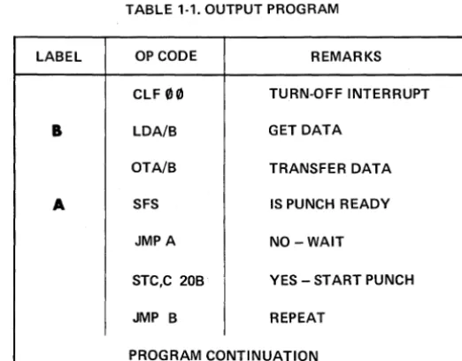
1-29. Table 1-1 provides a simple machine program for outputting data to the Tape Punch. This program
will transfer data at the maximum rate of 120 characters per second. Note that the data to be transferred
must be placed in the Buffer (I/O Interface Card) before the Punch is started.
TABLE 1-1. OUTPUT PROGRAM
lABEL OP CODE REMARKS
ClF
00
TURN-OFF INTERRUPTB
lDAfB GET DATAOTAiB TRANSFER DATA
A SFS IS PUNCH READY
JMPA NO-WAIT
STC,C 20B YES - START PUNCH
JMP B REPEAT
[image:14.618.193.454.450.654.2]Section II Students Manual
Volume XIV
HP2753A Tape Punch Theory of Operation
2-1.
INTRODUCTION
2-2. GENERAL
SECTION II
THEORY OF OPERATION
2-3. The HP2753A Tape Punch is a modified tape perforator which accepts and records up to eight bits of
data. In addition to supplying data, the computer (or other external source) must provide a punch command to
start the Punch whenever data is to be recorded. Special timing circuits ensure synchronization between the
computer and Tape Punch. Leader tape (punched feed holes only) is obtained through the manual operation of
a "buzZ:" switch and associated circuitry.
2-4. TAPE PUNCH LOGIC
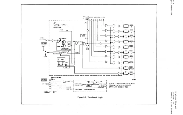
2-5. A simplified Tape Punch Logic diagram is given in Figure 2-1. All circuits in the Tape Punch use
negative (or ground) true logic. The Run FF may be set by an inverted punch command from the computer or
a "buzz" signal from the Buzz FF. These signals are gated with a false TO signal to set the Run FF. The
Run FF removes the "hold" signal from the 1.7 ms Gated Oscillator and Ring Counter. On the trailing edge
of the first TO pulse, a "flag" signal is sent to the computer signaling that the Punch is ready to accept data.
After 5 timing pulses have been generated (8.5 milliseconds), the next TO pulse resets the Run FF and the
timing circuits are inhibited.
2-6. With logic signals TO, RUN and BUZZ true, data inputs are "and" gated to the punching coils. This
initiates the punching operation. Actual punching occurs during time period TO only. Time periods T1 and T2
are required for punch pin retraction. Time period T3 advances the tape and T4 resets the Buzz FF if it had
been set by the "buzz" switch. A timing diagram is shown in Figure 2-1.
2-7. Note that the drive for the sprocket (feed hole) coil is enabled when TO and RUN signals are true.
Notice also that data cannot be punched when the BUZZ signal is true. At this time, the buzz signal sets the
tv I tv
IBURI
rq,
I I I +1211 PUNCH COM MAN~RA~l~~~r--DATA INPUTS~-l FLAG 1 2 :3 4 5 6 7 8
,---I
I
I
I
I
I
I
T4lro.RUNl
L
BUHJ
'-S'-o.
..r-t..
~l
DATA
GATE
L ____________________________
~-DATAJSPRKT r---D~;-_--=~:--l
' -_ _ +-.J'--- I FF', - = I
I PUNCH CMD. PUNCH CMt. I
I FROM SYSTEM TO DRIVER I
---ADVANCE
I
~~~::OM I---RESET 8U~ : EXTERNAL PROGRAMMING :
[image:17.792.24.782.67.546.2]L _ _ _ _ _ _ _ _ _ _ _ _ _ _ _ _ .J
Figure 2-1. Tape Punch Logic
.... 24'11'
PUNCH COMMAND AND DATA MUST REMAIN UNTIL FLAG OCCURS (TRAILING EDGE OF TO)
f-jW
;:0(1) (1) (")
o
M-~ 0' ::0 o ...
Section II Students Manual
Volume XIV
HP2753A Tape Punch Theory of Operation
2-8.
ELECTRICAL THEORY OF OPERATION2-9. GENERAL
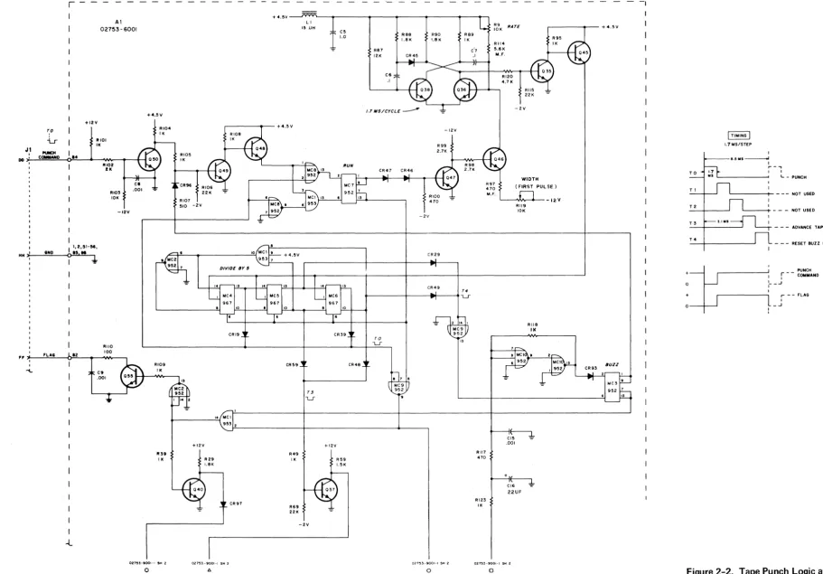
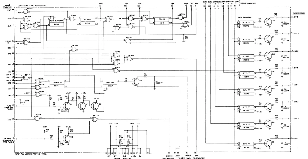
2-10. The Tape Punch electrical circuits are shown in Figures 2-2 and 2-3. Figure 2-2 shows the data
interface board (AI) and Figure 2-3 shows the main chassis circuitry. The following descriptions will
expli-citly reference these two diagrams located at the rear of this section. The number 8 coil driver assembly
only is detailed in Figure 2-3. All other coil driver assemblies (1-7) use identical circuitry.
2-11. DATA TRANSFER CIRCUIT
2-12. Up to eight bits of data from the data source are applied to the respective coil-driver circuits through
pins d, j, B, F, L, R, V, and Z of connector J1. (Figure 2- 3). All true data bits appear as a negative voltage
on the base of each normally-off input transistor (Q4 for number 8 coil-drive circuit). Normally-conducting
Q39 is connected to the collector of each input transistor through a diode. This places the collectors of the
input transistors essentially at ground potential, so the input transistors will not conduct. If the data bits are
true (negative), and Q39 is turned off simultaneously; the base of the input transistors are at a negative
poten-tial and the collectors are at a positive potenpoten-tial, so the input transistors still will not conduct. This action
turns on Q3, Q2 and Q1 (for the number 8 driver) and energizes the punch coil. If Q39 is turned off and the
input is false (positive) the input transistor's collector is held at ground inhibiting the punch driver coil
circuits.
2-13. PUNCH COMMAND CIRCUIT
2-14. A punch command at pin DD of connector J1 (Figure 2-2) turns conducting Q50 off. This places a
positive voltage on the base of Q49 turning it on. With Q49 conducting, the base of Q48 is effectively at ground
potential so the emitter of Q48 places a false input on pin 1 of "nor" gate MC8. Pin 2 of "nor" gate MC8 is
already false, so pin 13 becomes true and sets the Run Flip-Flop (FF). Setting the Run FF removes the "hold"
command from the oscillator gate and multivibrator (Q38 and Q36). The first pulse is generated by the circuit
which includes Q46 and Q47 and has a period of 1.7 milliseconds. This period is determined by the setting of
variable resistor R119. Succeeding pulses are generated by the multivibrator at a frequency determined by
the setting of variable resistor R9. The pulses are coupled to the divide-by-five circuit (MC4, ,MC5 and
Section II
Studentf;! Manual Volume XIV
Theory of Operation HP 2753A Tape Punch
2-15. The TO pulse derived from pins 13 of. MC4 and MC6 places a false input on pins 7 and 8 of "nor"
gate MC9. Pin 6 of "nor" gate MC9 is already false since it is connected to a false output at pins 7 and 13
of the Run FF. With both inputs false, the output at pin 9 of MC9 becomes true. This true condition
ener-gizes the sprocket and data solenoid coils as follows:
a. Sprocket Coils - Applying the true (positive) voltage to the base of normally-off Q94 (Figure 2-3)
causes it to conduct. This applies a negative voltage to the base of normally-off Q92 and causes it to
conduct. When Q92 conduCts, the base of normally-off Q91 becomes positive. Since the collector of
Q91 is connected to +24 volts through the sprocket solenoid coil, Q91 starts conducting. This energizes
the sprocket solenoid, which activates the punch and punches a sprocket hole in the tape.
b. Data Coils - The effect of applying the true (positive) voltage to pin 2 of "and" gate MC1 (Figure 2-2)
depends on the state of the Buzz FF. The normal state of the Buzz FF is reset, making pin 1 of MC 1
true. With both inputs of MC1 true, the output is true and a positive voltage is applied to the base of
normally-off Q40 causing it to conduct. When Q40 starts conducting, the base of normally-conducting
Q39 (Figure 2-3) becomes negative and Q39 stops conducting. This provides the second enabling signal
to the eight coil-driver circuits. If the data source indicates a false (positive) condition at pin J of
connector Jl, for example, normally-on Q39 stops conducting and the collector of Q4 becomes positive
allowing it to conduc.t. With Q4 conducting, the base of normally-off Q3 remains negative and Q3, Q2,
and Q1 remain off and the solenoid coil for this circuit (number 8) is not energized. If the data source
indicates a true condition, the base of normally-off Q4 becomes negative. Now, when Q39 stops
con-ducting and the collector of Q4 becomes positive, Q4 will not conduct because of the negative voltage on
the base. The base of normally-off Q3 now goes positive and Q3 begins conducting. This causes a
negative voltage differential between the base and emitter of normally-off Q2 and it starts conducting.
When Q2 starts conducting, the base of normally-off Q1 becomes positive. Since the collector of Ql
is connected to +24 volts through the solenoid coil, Q1 starts conducting. This energizes the number 8
solenoid coil which activates the tape punch mechanism and punches the tape track corresponding to that
data bit. The other seven coil-driver circuits operate in the same manner. If the "buzz" pushbutton on
the front panel was used to provide a tape leader, the Buzz FF is in a set state and pin 1 of "and" gate
MC1 is false. This inhibits all eight coil-driver circuits and prevents punching any data information
into the tape. Under these conditions, only the sprocket holes will be punched. into the tape for as long
as the buzz pushbutton is depressed.
Section II Students Manual
Volume XIV
HP2753A Tape Punch Theory of Operation
2-16. FLAG CIRCUIT
2-17. When the output at pin 14 of "and" gate MC1 (Figure 2-2) becomes true and enables the data
coil-driver circuits, pins 1 and 14 of "nor" gate MC2 also become true. This makes the output at pin 13 false
which turns normally-conducting Q55 off for 1.7 milliseconds (period of TO). The resultant pulse is supplied
to the data source as a "flag" signal (trailing edge) to indicate that the data has been punched into the tape.
The time periods T1 and T2 are utilized to withdraw the tape punch pins from the tape.
2-18. TAPE ADVANCE CIRCUIT
2-19. The T3 pulse derived from pins 10 of MC5 and MC6 places a negative voltage on the base of
normally-conducting Q37 (Figure 2-2) turning it off. The base of normally-off Q84 (Figure 2-3) now goes
positive and Q84 begins conducting. This causes a negative voltage differential between the base and emitter
of normally-off Q82 and it starts conducting. When Q82 starts conducting, the base of normally-off Q81
becomes positive. Since the collector of Q81 is connected to +24 volts, through the tape drive solenoid coil,
it starts conducting. This energizes the tape drive solenoid coil which activates the tape drive mechanism
and advances the tape into position for the next punch operation.
2-20. TAPE LEADER CIRCUIT
2-21. Pressing the "buzz" pushbutton on the front panel (Figure 2- 3) applies a positive true voltage to
pins 8 and 7 of "nor" gate MC10 (Figure 2-2). Since pin 6 is false, the output at pin 9 becomes false. This
makes the inputs at pins 1 and 2 of MC10 false, therefore the output at pin 13 becomes true and sets the
Buzz Flip-Flop (FF). The true output at pins 1 and 9 of the Buzz FF apply a positive voltage to the base of
normally-off Q49 turning it on. This sets the Run FF in the same manner as applying a punch command.
The tape punch will punch sprocket holes and advance the tape as long as the "buzz" pushbutton is depressed.
The T4 pulse derived from pin 13 of MC5 and pin 10 of MC6 is applied as a false input to pins 1 and 14 of
"nor" gate MC9. Pin 2 is already false, so the output at pin 13 becomes true and is applied to the reset
input of the Buzz FF. If the "buzz" pushbutton is still depressed, the set input will be true. Under these
conditions, the true state on the reset input will be unable to reset the Buzz FF so it will remain in a set
Section II
Theory of Operation
2-22. HOLD MODE
Students Manual Volume XIV
HP2753A Tape Punch
2-23. After completion of a punch operation. the Run Flip-Flop will reset as follows (unless another punch
command is received from the data source): at the end of a punch command. pin 1 of "nor" gate MC8
(Figure 2-2) is true. Pins 2 and 6 will become true at the end of the TO pulse. This makes the outputs at
pins 9 and 13 false. Pin 3 of "and" gate MC1 is connected to pin 1 of MC8. so it is also true. Since pin 6
is false, the output of "and" gate MC 1 is false. This makes both inputs to the Run FF false so the flip-flop
re-mains in the set condition. If another punch command is not received. the next TO pulse will make the input
at pin 6 of "nor:' gate MC8 false. The other input is already false so the output at pin 9 becomes true. NoW
both inputs to "and" gate MC'! are true so the output becomes true and resets the Run FF. This places a
"hold" signal on the gated oscillator and divide-by-five circuit. The tape punch will remain in this "hold"
condition until another punch command is received from the data source or the buzz pushbutton is depressed.
2-24. POWER SUPPLY
2-25. The tape punch contains three regulated DC power supplies (Figure 2-3) which provide +24. +12.
+4.5. and -2 volts. A circuit is also provided which removes the +12 volt supply voltage from the
coil-driver circuits to prevent punching false data information into the tape when the 115 V AC input power falls.
2-26. During normal operation. Q95 is normally-off and Q96 is normally-conducting. When power begins
to fail. Q96 is biased off and stops conducting. This makes the base of normally-off Q95 positive and it
starts conducting. The base of regulator transistor Q201 is now effectively at ground potential and the
+12 volt power is removed from the coil-driver input transistors (e. g. Q4. Q3). This prevents operation of
the data punch mechanisms by effectively locking the coil-driver output transistors off.
2-27.
MECHANICAL THEORY OF OPERATION
2-28. GENERAL
2-29. The Tape Punch consists basically of three major mechanisms:
a. Capstan Drive Mechanism
b. Perforator Mechanism
c. Reel Drive Mechanism
These mechanisms are diagrammed in Figures 1-1. 2-4. 2-5. 2-6 and 2-7. The Capstan Drive Mechanism
(Figure 2-4) is used to feed tape to the Take-up Reel mounted on the Reel Drive Mechanism (Figure 2-7).
The actual punching operation is controlled by the Perforator Mechanism (Figures 2-5 and 2-6) which
Students Manual
Volume XIV
HP2753A Tape Punch
r
-Al 02753-6001
+12V
I ',2,'I-M,
HH
I
-12V
RIIO
100
,,~ __ ~F~L~A~8~~~.2~ __ ~ __ ~~ __ ,
I
-l
C9.001
RI07 510 -2V
RIOS I. eR97 +4.5V--J~~~-~---~---~---.---~----~-, R69 22. L I
15 lJH
-2V R87 12. R88 L8K CR4!5
R90 Ra9 1.8K IK
-12V
- 2V
CR29
CR49
T4
~---+---__ ~--~L-r
"
RII7
470
RI23
I.
,---.... --- + 4.5 V
RII4 5.6. M.F. RI20 4.7. -2V WIDTH (FIRST PULSE)
'----"11,..,... ... - _ 12 V
Rtl9 10K RIIB II<
ct-1-.001 +~CI6 ':'
22UF
CR93 BUZZ
TO
T I
72
73
T4
I
TIMINGI
1.7MS/STEPSection II
Theory of Operation
e.' 1111 ---.I I
,...-.,
I I
L - PUNCH
'---t- - - - NOT USED NOT USED - - - ADVANCE TAPE
- - - RESET BUZZ FF
, -____________ ...J, r - - ~O:~~ND
I
+
o
+
0---1-...
: __ ...J
I
r - - FLAG
I
[image:22.1175.129.1041.84.719.2]Section II Students Manual
Volume XIV
HP2753A Tape Punch Theory of Operation
translates the electrical data (any 8-level code) into corresponding mechanical operations which facilitates
recording the data.
2-30. CAPST AN DRNE MECHANISM
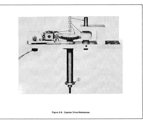
2-31. The Capstan Drive Mechanism is shown in Figure 2-4. Drive power is transferred from the motor
through a lug belt and pulleys to the input shaft (1). The bevel gear (2) transfers this power to the friction
clutch assembly (3). Pulsing the forward escapement assembly (4) causes its armature to release the friction
clutch momentarily. The clutch and capstan shaft rotate one step. The capstan (5), which is mounted on the
capstan shaft, rotates one step. The armature engages the next tooth of the clutch assembly, stopping the
action.
2-32. The forward escapement assembly is pulsed by the tape advance circuit (see para. 2-18) each time a
punch command is received and a timing ~ycle is initiated. The timing cycle may also be initiated by depressing
the "buzz" switch (see para. 2-20) on the front panel. The forward escapement is pulsed at T3 (5.1
milli-seconds after the leading edge of the last data pulse) when the punch pins are still in the tape. A further delay
of 1.3 milliseconds is provided by the inertia of physical members of the unit so that the punch pins have time
to retract before the tape is advanced.
2-33. PERFORATOR MECHANISM
2-34. The perforator mechanism, mounted on the front of the panel, consists essentially of one pivot
shaft, nine punch drive eccentrics, nine punch linkages and four clutch shafts (with gears molded on), all
enclosed in an oil tight case. The basic components of this mechanism are shown in Figures 2-5 and 2-6.
2-35. Drive power is supplied to the four clutch shaft driven gears through a drive gear mounted on the
motor shaft and centered within the four driven gears. Figure 2-5 shows the gears and their relationship to
each other.
NOTE
-The shaft (1) on the drive gear represents the motor
shaft for reference only.
Section II
[image:25.617.37.535.67.512.2]Theory of Operation
Figure 2-4_ Capstan Drive Mechanism
Students Manual Volume XIV
HP2753A Tape Punch
2-36. On the outer rim of each clutch is a gear (B. Figure 2-6) which is engaged with the gear (A.
Fig-ure 2-6) of a corresponding clutch to advance one-sixth revolution which in turn advances the eccentric one
full revolution executing one full punch stroke. The punch pin is driven up through the die-guide block
into the tape (Figure 1-1).
Students Manual Volume XN
[image:26.613.52.569.44.590.2]HP2753J\ Tape Punch
Figure 2-5. Perforator Mechanism - Power Transfer
Figure 2-6. Clutch - Eccentric Relationship
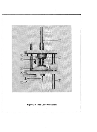
2-37. REEL DRNE MECHANISM
Section II
Theory of OperatiCln
2-38. The takeup reel drive mechanism, shown in F:igure 2-7, consists essentially of a differential gear
arrangement and a braking mechanism. Drive power to the reeling mechanism is supplied by the motor to
the input shaft (8) through a drive belt and pulleys. Rotation of the input shaft and the gear mounted on it
Section II
Theory of Operation
Students Manual Volume XIV
HP2753A Tape Punch
2-39. A tape tension arm on the front of the panel is positioned to rest on the tape between the capstan and
the takeup reel, forming a loop in the tape. As tape is fed from the capstan the loop lengthens, permitting
the arm to drop. This applies the brake (1) to gear (7), stopping its rotation. The differential gear must
[image:27.615.123.517.176.711.2]then revolve around the reeling shaft, rotating the shaft to take up the. tape.
Figure 2-7. Reel Drive Mechanism
Students Manual Volume XIV
HP2753J\ Tape Punch
Section III
Computer Interface
SECTION III
COMPUTER INTERFACE
3-1. INTRODUCTION
3-2. GENERAL
3-3. The HP2753A Tape Punch-to-HP computer interface is facilitated through the HP Tape Punch
Inter-face Card (02116-6045). This card is part of HP InterInter-face Kit 12536A which also contains the basic software
required to drive the Tape Punch and transfer data. However, this section will be limited to a description of
the Interface Card only: consult the software documentation provided with your particular computer system
for information relative Jo programming the Tape Punch.
3-4. OPERATION
3-5. A Tape Punch Interface Card schematic is included as Figure 3-1. An OTA or OTB instruction
must be issued by the computer program to transfer the eight least significant bits (0-7) from the A or B
Register to the Interface Card. The 100 signal which results from execution of these instructions enables
the Data Register on the Interface Card. A set Data Register Flip-Flop (Bit 1-8)FF enables a ground for the
corresponding coil driver in the Tape Punch (see para. 2-11).
3-6. A Set Control, Clear Flag (STC, C) instruction must be issued by the computer program. The STC
portion of the instruction sets the Control and Punch Flip-Flops. The C portion of the instruction resets
(clears) the Flag FF to prevent an interrupt signal from being sent to the computer before the data has been
punched by the tape punch. The set Punch FF applies a "punch command" to the tape punch, causing it to
punch the tape at tape punch time TO with the data received from the computer (see para. 2-13). Also at
tape punch time TO, a "flag" signal is applied to the Interface Card from the tape punch to initiate an SKF
(Skip .F'lag) signal to the computer, or with the Control FF set, initiate an interrupt signal to the computer
(depending on the method used in the program) indicating that the data has been punched. The "flag" signal
also causes the Punch FF to be reset.
Section III
Computer Interface
Students Manual Volume XN
HP2753A Tape Punch
3-7. The tape punch supplies a low-tape alarm signal to the Interfac e Card when the tape supply reel
contains only about 50 feet of tape. The Interface Card then provides a logic "one" to the bit-5 position of
the A or B Register upon receipt of a LIA or LIB instruction. This enables a programmed tape-status check
to prevent punching data when all available tape has been used.
3-8.
THEORY OF OPERATION3-9. GENERAL
3-10. Data transfer is initiated by an OTA or OTB instruction which enables the IOO signal. The 8 bits of
data from the A or B Register then set the Data Register FF's on the Interface Card to provide a ground for
the punch coils in the tape punch. The STC and CLF instructions (or STC, C) are used to start the timing
circuits in the tape punch; and to set the Control FF and clear the Flag FF on the Interface Card. The
Punch FF, when set, sends a ''punch command" to the tape punch to start the timing circuits. The tape is
punched at punch time TO, and after 5. 1 milliseconds (punch time T3) is advanced to the next feed hole by the
timing circuits. The tape punch also sends a "flag" at TO, which resets the Punch FF and sets the Flag
Buffer FF on the Interface Card. Two methods may be used to signal the computer to output data to the
tape punch:
a. Interrupt Control
b. Wait-for-Flag
3-11. INTERRUPT CONTROL
3-12. The interrupt system is enabled by a STF (SC~~) instruction which sets the Flag Buffer and Flag Flip-Flops. An OTA or OTB instruction then enables the Data Register FF's which enable a ground drive
for the punch coils. The STC and CLF instructions set the Control and Punch FF's, and reset the Flag FF
as described earlier.
3-13. The Punch FF issues a"punch command"to start the tape punch timing circuits. These circuits count
from TO through T4 at 1. 7 millisecond intervals. The tape is punched on the leading edge of TO. The "flag"
is generated on the trailing edge of TO. This negative-going flag signal turns Ql off, Q2 on and Q3 off. The
Punch FF is then reset and the Flag Buffer FF is set to prepare for an interrupt. At computer time period
Students Manual Volume XIV
HP2753A Tape Punch
Section III
Theory of Operation
to the I/O Address Card. The computer can now output data to the Data Register FF's again. Note that
using the interrupt control method allows the computer to perform other operations while waiting for the
interrupt to occur.
3-14. WAIT-FOR-FLAG CONTROL
3-15. The interrupt system is disabled by a CLF (SC~0) instruction which resets the Flag Buffer and Flag Flip-Flops. After the tape punch punches the data. the Flag Buffer FF and Flag FF are set. Then a SFS
instruction (Skip if Flag Set) allows the next instruction (JMP) to be skipped by enabling the SKF signal to
the computer. Note that when using the wait-for-flag method. the computer cannot perform any other
opera-tions until the flag is set. This allows for punching any number of characters desired through looping the
OTA/B instructions.
Students Manual
Volume XIV
HP2753A Tape Punch
SRO PRH SIR IAK flGL IRQL PRl o I 2 3 4 5 6 7 FROM COMPUTER
Section III
Computer Interface
~ 02116-604~ (CARD REV H-824-6) 19 23 32
COIIoW'UTER _ _ _ _ _ _ _ _ _ _ _ _ _ _ _ _ _ _ _ _ _ _ _ _ _ '.:+ _ _ _ _ _ _ _ _ =1 _ _ _ _ .~ _ _ _ _ _ _ _ _ _ _ ...;.10
~~M~ _ _ _ ~I,-~~C~
4 I 3
lt80 lt80 lt80
lOBO
lt80 I(I!()IOBO IOBO}
~ 38 ~
45 42 51.
~ _!!2 _ _ _ _ _ _ _ _ _ _ _ _ _ _ _ _ _ _ _ _ _ ,+4.5V ~14~---~~~----~---+---4---~----,
1 MCZ7A 1 MC45A loICZ6B
~6C ~4~C
pu.--MCI78. Sll' ~ ...---:.r'
~....,\ 6 11 114 13 2 2"-;F;-L;-AG;;-;F;-F-t!L19~-+--....!6!f'''':::':~''3 +4.511-1-fl }l:IO=----"I Al , h~-!21--:I;:;R;;;0;-;:F~f-"}!.:1 94-+-.!l~14
FLAG BUFfER F,;r 14I
3 } 5nL1
'O I I1 ~4.5Vn6B
l
6'
M05'T."
1 61 MC,5 1713 I MCISAClf -'-7l ...
_-+~---"1:
+~~5LV_6
_ _ _I3-+-+--I __
2 _ _ M_C_4_6 _ _ _+-___
...J~
' "~
:~-:
:""~:"--4
~
MC45B POPIO -'.17:, _ _ _ 3"-{
(B) 1
,
+4.5V 6 13MC26A
IEN~8~.---+---+---~2r--~
d }~'4~---~~~
~ .MC25C
SfS~~---~----~~---l---t-t======~
10
, 7 MC37C
SfC~~L.'---_+---_4---~~---~--~::::::::::tl.~IO
13 MC25B 6 MC47B 6 91L---4--+--.---l
t:~g
-2VDATA REGISTER RI7
IK
riE
7 L BITBfF 197 MC44B l .
-..~ _ _ _ _ _ r--I..!!.. + 4. 5V
2 l - - - l
RI6
II<
ffi
BIT 7 FF r'3 I MC44A " +4.5Vrti
BIT6fF I'7 L - - - - I L . MC34B
RI5
II<
+4.5V
14~47A
.1 \ . _ _ _ _ _ _ _ _ _ _ _ _ _ _ _ _ _ _ _ _ _ _ _ _ _ _ _ _ _ _ _ _ _ _ _ _ _ _ _ _ _ _ _ _ _ _ _ _ _ +_~--~~~_+-+_--~---~ RI4
loo~~~---+_----~---~---~21 ~3 t=======~~~'-~;;::-~_~'~~~~
LSCM -'.'.,4 ,...._~MC27C Fo~
ret,
L _B_'_T_~_F_F _ _4113lSCl ..ll-"e ... ---~ MC34A ..
10 H"iMC37A
1
2 R8I
IOG(B) ... - - - ' h.--+-~:.r;:;:;;:;:;:;;;;:;;__;.;1'9 6 13 IK Q4
b,
+4.5\1
STC 22 I 14 I-CON ___ TROL _ _ FF---I PUNCH fF I
r~OOPF
~MC37B I I
I
I til} 6 MC36 17" 2 I MCG 7
CLC~2~1~_---+-4-.5-V~-~-~tl21
MC2r.1.3-~~r-~-~~---1~+4-.-5\1----2V--+-4--.5\1
~8
~
CRS ....:''13 ... _______
-+_-'1'
14 +'2\1 -1211 !,R4 R5 ~F7
1 TO FLAG
~'
r&
IK~ ~2'2K
IK +4.5\11
IT
~~
~
01 02 03 flAG~2~3
...---+---~--~~~-~(
rr
(FROM TAPE +
"""'CHI CI
I
,OooPF_=_
-=-MC71S ~7A
101 ~M~~---~ il~44~ )}~15~ _ _ _ _ _ _ _ _ _ _ _ _ _ _ _ _ _ _ _ _ _ ~6~7
...
,.
+12V R26 II< -12V R2B 10K +4.5\1!
R29 ~470+12V -12V +4.5V -2\1
RI3 IK
rtl'
BIT4 Ffr'
6
7 l - - - l MC24B • ' t -_ _ _ _ ...J +4.5\1
" L - - - l
RI2 II<
~
I BIT 3 FF 1'3 MC24A 14. ' -_ _ _ _ _ --.J +4.5\1
RII IK
Hti
BIT 2 ffr'
7 L - - - - I
"-_MC_'_4_B_--.J. + 4. 5V
R25 10 TAPE PUNCH r -___ ..,.IOO"""_~--->-i-'4'-BIT 8
I
1CI4 012IOOOPf I
1
R24
.-_""OyOy----<~---!-'=O-BIT 7
1
r
CI3011
1000Pf
R23
r - _ ... 'OyO __ ~r---_+,3,-BIT 6
1
1CI2 010IOOOPF
R22
r-_..,IOOIIV-_~----<~.:::c-BIT 5
1cII
Q9
l'oooPf
~ 1
r---'Wt~-1--_+-=2-BIT 4
lclO
OB
l'oooPf
R20
r -__ ... 'OO..,.,._~----<--+-=B,-BIT 3
1c9
1 l'OOOPF07
RI9
, __ ... 'OO..,.,._ ... _ _ -ir-:'_ BIT 2
lIC8
10001'1'l
os
R27
013 CI8 2.2UF CI5 2.2llF . - _ ... RIB 'OO..,.,. __ ... _____ -I..::A:.... BIT I
LOWT~ ~1~.~---___<~--
...
2yK __ -~-~AlARM (FROM , +
.... ""'" L
________________
J~:~
__
-=-_ _ _ _ _ _ _ _ _ _ _ _NOTE: ALL lOGIC IS POSITIVE-TRUE.
+--~~,I-';~~-4~r:-
~~O
051
2.~ 2~ I ~D
I
r
+ +1\n
h
~
LttiL
-B~-TC-~-~--1[:+45V
_=_r
1000Pf:43[.44
~
-,t
~
3!I40f
471.-~--+.O,.j,
,':":, •• -- - -
---::ceo:o!---:Mt B8 ----,2=-:1, - -i2 - - - --- - - ----1,
+12\1 -12V GND +4.5\1 -2\1 lOBI e GND PUNCH SKF
[image:32.1175.39.1094.114.658.2]Students Manual Volume XIV
HP2753A Tape Punch
Section IV Maintenance
SECTION IV
MAINTENANCE
4-1. INTRODUCTION
4-2. GENEHAL
4-3. This section provides recommended maintenance intervals and procedures. The preventive
mainten-ance intervals are based upon intermittent use and assume that one 1, ODD-foot roll of tape is perforated each
hour. Detailed information on how to service the various mechanisms is provided in paragraphs 4-12 thru
4- 33 (Maintenance Procedures)'
4-4. PREVENTIVE MAINTENANCE
4-5. DAILY MAINTENANCE
4-6. Clean the die block, capstan and tape track, using an air blast or a brush. Inspect the unit for overall
cleanliness and proper operation. The die block may at times become clogged with chad or bits of tape which
cannot be removed with a brush or compressed air. This is not likely with regular maintenance. See Die
Block Cleaning, (para. 4-13).
4-7. Check general punch operation. Check for proper spacing, tape tearing, double punching and bit
de-letion.
4-8. 125-HOUR MAINTENANCE
4-9. Perform the Daily Maintenance to ascertain that the unit is operating correctly before you begin the
125-Hour Maintenance. Then proceed as follows:
a. Static Inspection
1. Inspect the Capstan Drive Mechanism for excessively worn or damaged parts, and for lug
belt wear and alignment.
2. Check escapement actuators for cleanliness and proper clearances (Figure 4-9).
3. Inspect the reeling mechanism for excess ively worn or damaged parts. Check for belt
wear and alignment. Check tension arm positioning (Reeling Adjustment, page 4-10).
b. Dynamic Inspection
1. Observe tip to clutch tooth operation in the Capstan Drive Mechanism - see that the
arma-ture tips are contacting clutch teeth squarely, with not more than . 01~" (. 38mm) overhang. 2. Observe the tape tens ion arm for smooth operation.
Section IV Maintenance
Students Manual Volume XIV
HP2753A Tape Punch
4-10. 250-HOUR MAINTENANCE
4-11. Perform the Daily Maintenance to ascertain that the unit is operating correctly before you begin
the 250 Hour Maintenance. Then proceed as follows:
4-12.
4-13.
4-14.
a. Static Inspection
1. Inspect the Capstan Drive Mechanism for excessively worn or damaged parts. Check fOI'
lug belt wear and alignment, and for excessive shaft play.
2. Check escapement actuators for: anti-residual shim wear; armature tip wear; clutch
tooth wear; cleanliness; clearances (F igure 4-9).
3. Inspect the Reeling Mechanism for worn or damaged parts. Check for belt wear and
alignment. Check tension arm positioning (Reeling Adjustment, page 4-10).
4. Lubricate the unit according to the Lubrication Procedures given in the Tape Punch Manual.
b. Dynam ic Inspection
1. Observe tip to clutch tooth operation in the Capstan Drive Mechanism. See that armature
tips are contacting clutch teeth squarely, with no more than. 015" (. 38mm) overhang.
2. Observe the tape tension arm for smooth operation.
3. Check punch operation for clean holes and proper spacing. Check also for tape tearing,
double punching and bit deletion. Observe the data drive pulses on an oscilloscope.
4. Observe the Reeling Mechanism for smooth operation. See that the belts are not slipping.
MAINTENANCE PROCEDURES
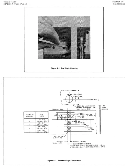
DIE BLOCK CLEANING
The die block may at times become clogged with chad or bits of tape that cannot be removed with a
brush or air blast as noted under Daily Maintenance. When this happens, pass a .005" (. 13mm) cleaning shim
through the tape track, from right to left (see Figure 4-1). A die block too badly clogged to allow passage of
a cleaning shim may require removal for cleaning.
4-15. STANDARD TAPE DIMENSION ADJUSTMENTS
4-16. The HP2753A is designed to operate within the hole spacing requirements of American Standards
Association (ASA) specifications. (See Figure 2-4.) Hole spacing may be defined in two areas:
edge-to-hole (centerline of sprocket edge-to-hole to three-edge-to-hole edge of tape) and edge-to-hole-to-edge-to-hole (10 edge-to-holes per inch).
Edge-to-hole spacing is controlled by the Tape Guide Insert and Capstan Positioning. Hole-to-Edge-to-hole spacing is
con-trolled by the Stripper, the Retainer, and the Capstan Drive Mechanism.
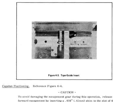
4-17. Tape Guide Insert. Run a short length of test tape, and with a tape hole gage check to see that thc
sprocket hole centers are. 392
:!:
.004" (9.9:!: •
Imm) from the three hole side, as shown in Figure 4-2. If not, loosen the two allen head mounting screws on the tape guide insert (Figure 4-3). Re-position the inset·tand check the tape again.
Students Manual Volume XIV
HP2753A Tape Punch
NUMBER OF CHANNELS 8 7 6 5 TAPE WIDTH 1 ± .003"
(25.4mm ± .076) 7/8' .003"
(22.2mm ± .076) 7/8' .003"
(22.2mm ± .076) 11/16' .003"
[image:36.615.48.556.48.727.2]17.5mm ± .076
Figure 4·1. Die Block Cleaning
\
i
_ ' \ t ' . 1 2 .003 (.076mml('~5mm)
"-
,/
! ) TRUE TRAC~fODE HOLE LOCATION WITH RESPECT TO NOMINAL .100 REFERENCE EDGE INCH (2. 54mm) GRID.
. J 2 ' .004
.3ob
+ 002 .046 -:001 DIA.(7.6rm).2OO I / (1. 17mm + .05
°l
(9.96mm ±.10l (5.08,m) .100 ~i
-
.0252. 54mm
!
. "
<2.~.;:;'
t (5.0~mm).3OO1
,J
(7·t2mm)400 (\0
·r
mm) 500(12.;-Omm)
}
.072' .002 DIA . . /
(1.83mm ± .05)
. 1 0 0 ' . 0 0 3 - ' - - FEED HOLE SPACING
(2.5mm ± .076)
i -CUMULAT VE SPACING ERROR I
l~
·OO4(.IOOmm) (NOMINAL)
UP TO' .0\0 (.25mm) IN \0 SPACES(I.O INCH -- 25.4mm) UP TO' .025 (.63mm) IN 50 SPACES (5.0 INCH -- 127mm)
Section IV Maintenance
Figure 4-3. Tape Guide Insert
Students Manual Volume XIV
HP2753A Tape Punch
4-18. Capstan Positioning. Reference Figure 4-4.
CAUTION
-To avoid damaging the escapement gear during this operation, release the
forward escapement by inserting a .016" (. 41mm) shim in the slot of the
armature limit. Hold the escapement gear with the fingers. The capstan
should have. 001 - .002" (.025 - . 050mm) clearance from shims (barely
perceptible end play).
This operation is normally not required in the field, unless shims have been lost during repair. Position the
capstan to line up with the sprocket punch by installing or removing shims on the shaft behind it. To remove
the capstan, first move the retainer to the load position. Remove the collet pin cap and the tape stripper.
Remove the collet pin by turning the pin clockwise and pulling at the same time. Remove the capstan, install
or remove the required shims and replace the capstan. To retighten the capstan, re-insert the collet pin.
Push it all the way in, twisting clockwise at the same time. This will secure the capstan to the shaft.
4-19. Stripper. Loosen the stripper's two mounting screws. Position the stripper to line up with the
capstan.
NOTE
-Stripper adjustment affects Retainer adjustment. Check Retainer.
4-20. Retainer. Insert an allen wrench through the access hole on top of the retainel'. Loosen the mounting
screw. Thread tape between the retainer and the capstan, and push the retainer snugly (but not too'tightly)
against the tape. If after adjustment the tape does not move, the retainer may be too tight against the tape.
If the hole spacing is erratic, the retainer may be too loose.
Students Manual
Volume XIV Section IV
[image:38.617.58.558.68.371.2]Maintenance HP2753A Tape Punch
Figure 4·4. Capstan Removal.
4-2 L Capstan Drive Mechanism. The center-to-center hole spacing on the Tape Punch must be
main-tained at 0.100 :!:" .003" (2.54
± .
08mm) and the accumulated spacing error over five inches of tape must be within±
.025" (. 64mm). Check and adjust spacing as follows:4-22.
4-2:1.
4-24.
a. Measure the spacing over a length of tape containing exactly 50 sprocket holes. The distance
from hole one to hole 51 (leading edge to leading edge) should be between 4.975 and 5.025 inches
(12.64 and 12.76 centimeters). Tally tape gage
#
T18118 may be used for an approximate spacingcheck.
b. If the measurement is outside of the limits specified, loosen the clamping screw (1, Figure 4-5)
on the capstan adjusting plate and turn the adjusting screw (2). Turn the screw clockwise to lengthen
hole spacing; counterclockwise to shorten it. See that the adjust lever (3) is hard against the
adjust-ing screw. Tighten the clampadjust-ing screw.
c. Repeat these steps as necessary to secure correct hole spacing.
d. If the above adjustment proves insufficient, return the adjusting screw to its mid-point. Loosen
the capstan as described in Capstan Positioning. Rotate it one-half step in either direction, and
retighten. Repeat steps a-d.
ESCAPEMENT ADJUSTMENTS, PERFORATOR MECHANISM
The following adjustments must be made with the clutch bank removed.
Armature Tip. Tip adjustment affects all escapements on a clutch bank at once. Loosen the four 6-32
Section IV Maintenance
[image:39.617.49.547.45.767.2]4-6
Figure 4-5. Hole Spacing Adjustment
Figure 4-6. Armature Tip Adjustment
Students Manual Volume XIV
Students Manual Volume XIV
HP2753A Tape Punch
Section IV Maintenance
4-25. Armature Spring Tension. Proper air gap must be achieved before making this adjustment. Hold
the adjusting screw with an allen wrench. Turn the 6-32 elastic stop nut mounted on it until it takes 50 grams pull at the tip of the armature to achieve first motion. Force exerted must be 90° from the armature, as
[image:40.617.100.503.151.375.2]shown in Figure 4-7.
Figure 4·7. Armature Spring Tension
4-26. Punch Phasing. When a clutch bank is replaced on the Perforator Mechanism, its punches must be
phased with those of the other clutch banks. This insures that all punches called are in and out of the tape at the same time. To check phasing, run a short length of all-hole tape, and shut the unit down. Remove the die plate. See that all punches are the same distance below the exposed surface. An out-of-phase punch will protrude above the other punches. When a punch is out of phase, mark its clutch so that it can be rotated and then brought back to its original position. Rotate the clutch until its punch is even with the others. Remove the clutch bank and rotate the clutch back to its original position, as marked. (See Figure 4-8.) Replace the clutch bank and recheck punch phasing.
4-27. Escapement Adjustments, Capstan Drive Mechanism. Figure 2-9 shows the tolerances to which the
escapement assembly in the Capstan Drive Mechanism must adhere. Note that units incorporating the Re-verse Option contain two such escapements. Adjustment procedures are identical for both forward and re-verse escapements, but clearances differ and therefore require different size gages. The following procedures are based on a forward escapement. But they include gage identification for reverse escapements.
4-28. Heel Gap. Insert a .016" (. 41mm) gage into the slot of the armature limit as shown in Figure 4-10.
It must slip in easily. Repeat with a .018" (. 46mm) gage, and see that it slips in with perceptible drag. Use
Proto gage kit
#
OOOE, or equivalent. To adjust, loosen screw "A" and reinsert the. 018" gage; press the armature limit firmly against the gage and tighten screw "A" securely, taking special care that the coil framedoes not pivot on the bracket at point "B".
Section IV Maintenance
4-8
[image:41.618.47.554.50.714.2]A. ARMATURE AT REST
Figure 4-8_ Phasing Adjustment_
Students Manual Volume XIV
HP2753A Tape Punch
tr;;;!~~~~~~r=======j~=4='
.()(18 + .002, - .001"B. ARMATURE PICKED
Figure 4-9. Escapement Tolerances
(.20 + .05, - .03mm) [revo .... --.OIO ± .003'1
Students Manual Volume XIV
[image:42.623.125.476.81.672.2]HP2753A Tape Punch
Figure 4-10. Heel Gap and Tip Clearance.
Figure 4-11. Tip Clearance Adjustment.
Section IV Maintenance
Students Manual Volume XIV
HP2753A Tape Punch
4-30. To adjust tip clearance, loosen slightly the assembly mounting screws shown in Figure 4-11. Place
a small screw driver or awl between the mounting screws and bracket, and rotate the assembly in the dcs ired
direction. Retighten the mounting screws. An alternate method is to tap the assembly in the desired din;ction;
point "A" or
"c"
to reduce clearance, and point "B" or "D" to increase it. Great care must be taken to avoiddistorting the coil frame or bracket. In this respect, note that points "A" and "D" are on the bend of the
brack-et, applying force directly upon its shaded area.
4-31. Armature Spring Tension. Adjust the armature spring for 190 - 220 grams tension, meaSllt'cd at the
armature end of the spring. Hold the adjusting screw (Figure 4-11) with an allen wrench. Turn the 6-:l:!
elas-tic stop nut mounted on it until it takes 200 grams pull at the spring to achieve first motion. Force excl'tcd
must be 90° from the armature, and the armature must be free of contact with the control sleeve.
4-32. REELING ADJUSTMENT
4-33. Adjust the Reel Drive Mechanism so that the tension spring is near maximum extension with the brake
hard against the brake gear. Adjust the Tape Tension Arm so that in its farthest counterclockwise travel it
does not protrude beyond the edge of the panel, and it holds in position at the opposite end of its travel.
4-34. WEAR POINTS, ESCAPEMENTS
4-35. Most parts in the HP2753A which are subject to wear will show this wear in an obvious manner. A
worn wave washer may result in excessive end play. But some parts particularly in escapement assemblies
-are less direct in calling attention to themselves. This section will identify these parts and define "wear" in
terms of replacement need. The worn parts shown in Figure 4-12 are not necessarily those used in a current
Tape Punch. The wear points, however, are representative of what to look for.
4-10
a. Clutch Teeth: Wear on the clutch teeth occurs where the armature tip strikes the tooth, and
shows an indentation in the leading edge of the tooth as shown in Figure 4-12A.
b. Anti-Residual Shims: Anti-residual shims show wear in three areas: the slot where the shim
fits over the bracket, the area where the shim strikes the pole of the coil, and the edge. Figure 4-128
shows a badly worn shim. Note the impact scars, the uneven tip and the jagged edge. Any of these
indicates the need for replacement.
c. Bracket: Wear on the bracket occurs where the anti-residual shim strikes its bottom edge,
shown in Figure 4-12C.
d. Armature: Wear points on armatures are similar to those on anti-residual shims. Figure 4-12D
shows a Capstan Drive armature. Though this is of a different design from those in the Perforator
Mechanism, wear points are the same.
e. Armature Limit: Wear on the armature limit is evident in deformation of the slot that receives
Students Manual Volume XIV
HP2753A Tape Punch
[image:44.620.57.550.73.704.2]HnVLETT
IE
PA.CKARD,
. ~
.
.
.
11000 WOLFE ROAD, CUPERTINO, CALIFORNIA 95014, TELEPHONE 408 257-7000, TWX 910-338-0221 EUROPE: 1217 MEYRIN-GENEVA, SWITZERLAND • CABLE "HEWPACKSA" TEL_ (022) 41_54.00