Stabilization of a Wind Farm Using Static VAR
Compensators (SVC) Based Fuzzy Logic Controller
M. G. Hemeida
*, H. R. Hussien, M. A. Abdel Wahab
Department of Electrical Engineering, Faculty of Engineering, Minia University, Egypt
Copyright © 2015 Horizon Research Publishing All rights reserved.
Abstract
Wind energy is a cost competitive andenvironmentally clean renewable energy sources. Wind farm capacity connected to power system increasing rapidly worldwide. During transient conditions wind farm drive a large reactive power which in turn causes voltage instability. In this paper, Static VAR Compensator (SVC) based fuzzy logic controllers (FLC) has been implemented to improve transient stability and damping power oscillations of a wind farm connected to power system. Different fault types and different fault durations were considered for the study to investigate the effect of the SVC based FLC on system stability. The suggested fault types are, single line to ground fault, double line fault, and three lines to ground faults. The different duration faults are 50ms, 80ms and 100ms. Different locations are considered for the SVC at the studied system. The proposed controller provides the wind farm system with damping effect during transient condition and provides much smoother and quicker response in the post-fault conditions. The proportional plus integral (PI) controller is used for the comparative study. The studied system consists of wind farm represented by double fed induction generator (DFIG) connected to utility grid.
Keywords
Doubly Fed Induction Generator, Fuzzy logic control, Static VAR Compensators, Wind Farm1. Introduction
Energy consumption increases gradually due to the rapid advance in the industrial sectors, also the deficit in fossil fuel and increased energy demand turned the world's attention towards the renewable energy resources. Wind energy becomes one of the mainstream power sources in many countries all over the world. Renewable energy stations are friendly to both consumer and environment, due to it requires shorter construction time[1-6]. The flexible alternating current transmission systems (FACTs) devices are the most suitable promise tools for voltage and dynamic stability improvement of wind energy systems connected to grid as well as sand alone. There are many useful types of
FACTs devices are applied successfully for improving the dynamic stability of wind energy systems connected to grid. Static synchronous compensators, (STATCOM) and static VAR compensators are used widely for improving the voltage and dynamic stability of wind energy systems.
for a large induction-generator based wind park have been compared. The obtained results showed that the conventional switching of capacitors provides wind park to meet the Nordel gird code requirements on low voltage ride through, and the rating required is the same as SVC and STATCOM[10]. A fixed excitation capacitor(FC) in parallel with the thyristor switched capacitor(TSC) and the thyristor controlled reactor(TCR), static VAR compensator (SVC) has been applied to regulate and stabilize the generated terminal voltage of the single-phase self-excited induction generator(SE1G). The traditional proportional plus integral (PI) controller has been applied to adjust the equivalent capacitance of the single-phase SVC in the output of the single-phase SEIG[11]. The enhancement process of applying static synchronous compensators (STATCOM) has been compared to the thyristor controlled static var compensator (SVC) in low voltage ride through (LVRT) capability of wind farms using squirrel cage generators. The LVRT has been used as an indicator for transient stability margin. The obtained results proved that when the rating of STATCOM increased it can provide an increased transient stability margin and thus enhanced LVRT capability. Compared to the SVC, the STATCOM gives a larger contribution to the transient margin as indicated by both calculations and simulations[12-15]. The Fuzzy logic Control (FLC) is the most applicable advanced technique that used widely nowadays in small devices as well as large devices. The FLC response is dependent on the studied system performance, which makes their performance better than the conventional control approach[16-17]. The neural network[18] has been applied to control the SVC for voltage stability as well as transient stability. The hybrid neuro-fuzzy control approach has been applied successfully for SVC[19].
This paper introduce the application of fuzzy logic control (FLC) approach to static VAR compensator (SVC) for voltage and transient stability of wind farm system connected to utility grid. To investigate the effectiveness of the SVC on the system stability, different types of faults and different fault duration is considered. The SVC is located in different locations to indicate the most suitable location. The simulation results indicate the effectiveness of the proposed system in improving the stability of the wind farm system connected to utility grid.
2. Wind Turbine Doubly Fed Induction
Generator
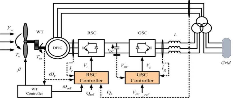
The wind turbine (WT) with DFIG system is an induction type generator in which the stator windings are directly
connected to the three-phase grid and the rotor windings are connected to grid through three-phase back-to-back pulse width modulation (PWM) converters. The back-to-back PWM converter includes three parts: rotor side converter (RSC), grid side converter (GSC) and DC Link capacitor placed between the two converters. It's controller includes three parts: rotor side converter controller, grid side converter controller and wind turbine controller as shown in fig (1) in which the grid-side converter and rotor-side converter, are controlled independently of each other[4].The main idea is that the rotor-side converter controls the active and reactive power by controlling the rotor current components, while the stator-side converter controls the DC-link voltages and ensures a converter operation at unity power factor (zero reactive power). Depending on operating conditions of the rotor, the power is fed into or out of the rotor. In an over synchronous condition, power flows from the rotor via the converter to the grid, whereas power flows in the opposite direction in a sub-synchronous condition. In both cases, the stator feeds power into the grid [20].
2.1. Wind Turbine Model
The wind turbine is characterized as in [21] by non-dimensional curves of the power coefficient
C
p as a function of both tip speed ratio and the blade pitch angle β, The tip speed ratioλ
is the ratio of linear speed at the tip of blades to the speed of the wind. It can be expressed as follows: wV
R
Ω
=
λ
(1)where R is the WT rotor radius, Ω is the mechanical angular velocity of the WT rotor and
V
w
is the wind velocity. For the wind turbine used in the study, the following form approximatesC
p
as a function ofλ
and β:β
λ
β
λ
π
β
.0
00184
(
3
)
3.
0
15
)
3
(
sin
)
0167
.0
44
.0
(
−
−
−
−
−
=
pC
(2)The mechanical torque of the wind turbine, Tm can be calculated using equation [22]:
λ
σ
22
1
w pm
AC
V
T
=
(3)Figure 1. Structure of DFIG Wind Power Generation System connected to utility grid
2.2. DFIG Mathematical Model [21-23]
The voltage and magnetic flux of the stator can be written as qs s ds ds s
ds
R
i
d
dt
V
=
+
λ
−
ω
λ
(4)ds s qs qs s qs
dt
d
i
R
V
=
+
λ
+
ω
λ
(5)dr
i
m
L
ds
i
s
L
ds
=
+
λ
(6)qr
i
m
L
qs
i
s
L
qs
=
+
λ
(7)The voltage and magnetic flux of the rotor can be written as qr r e dr dr r
dr
R
i
d
dt
V
=
+
λ
−
(
ω
−
ω
)
λ
(8)dr slip qr qr r qr
dt
d
i
R
V
=
+
λ
+
ω
λ
(9)dr i r L ds i m L
dr = +
λ
(10)qr
i
r
L
qs
i
m
L
qr
=
+
λ
(11)where λdsand
λ
qsare the direct and quadrature axis stator magnetic flux; λdrandλ
qrare the direct and quadrature axis stator rotor magnetic flux;L
s
,L
r
, andL
m
are the stator, rotor, and magnetizing inductances; Vdsand Idsare the stator direct axis voltages and currents; Vqsand Iqsare the stator quadrature axis voltages and currents; Vdranddr
I are the rotor direct axis voltages and currents; Vqrand qr
I are the rotor quadrature axis voltages and currents
V
r
and
I
r
are the rotor voltages and currents;R
r
andR
s
are the rotor and stator resistances;ω
s
,ω
r
are the synchronous and rotate angular frequencies, respectively,slip
ω
is the slip frequencyr
s
slip
ω
ω
ω
=
−
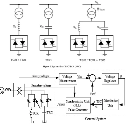
(12)3. Static Var Compensator (SVC)
[image:3.595.103.513.77.252.2]Figure 2.Systematic of TSC/TCR (SVC).
Figure 3. SVC control system
3.1. Operating Principle of SVC
Fig(3) shows Schematic Diagram of SVC control system simulated in MATLAB. The control system consists of: A measurement system for measuring the positive-sequence voltage to be controlled, A voltage regulator that uses the voltage error (difference between the measured voltage
V
m and the reference voltageV
ref ) to determine the SVC susceptance B needed to keep the system voltage constant, A distribution unit that determines the TSCs (and eventually TSRs) that must be switched in and out, and computes the firing angle α of TCRs and A synchronizing system using a phase-locked loop (PLL) synchronized on the secondary voltages and a pulse generator that send appropriate pulses to the thyristors[11]. The SVC can be operated in two different modes: In voltage regulation mode and in Var control mode (the SVC susceptance is kept constant) [22].3.2. SVC Mathematical Model [17]
TCR is designed by an inductance coil L connected in series with two anti-parallel poled thyristors. Through the variation of the firing angle α, the amplitude of the fundamental reactive current can be controlled as follow:
))
2
sin(
2
2
(
π
α
α
πω
−
+
=
L
V
I
(13)[
]
− − +
− = −
= 1 2(π α) sin(2α)
πC
L L C TCR C
SVC B B X X X X
B (14)
TSC is designed by a fixed condenser switched on and off using a bidirectional thyristors interconnected in series. So, its current varies from 0 to Imax. The condenser is connected to a coil in order to avoid a resonance with the supply network. The current that flows through the capacitor is given by the following expression:
)
cos(
1
)
(
2 2C
t
n
n
V
t
i
ω
ω
ω
−
=
Where
L c
X
X
LC
n
=
=
2
1
ω
(15)The combination of both TCR and TSC provides a good dynamic compensation. The combined reactances are given by
C
j
L
j
X
SVC=
ω
−
ω
(16)3.3. SVC V-I Characteristics[22]
When the SVC is operated in voltage regulation mode, The SVC voltage varies between Vmin and Vmax as shown in fig (4). The aim is to maintain the voltage at a desired constant value. The calculation of the slope allows us to know the voltage drop. The characteristic equation of the slope is given as follows:
max max
max max
L L
C C
I
V
I
V
Slope
=
∆
=
∆
(17)The V-I characteristic and operating region of SVC described by three equations as follow [21]:
1) Regulation zone: this zone is governed by (18) SVC SVC ref
SVC
V
X
I
V
=
+
(18)(
−
B
Cmax˂ V ˂B
Lmax)2) Zone of under-voltage: in this zone the SVC behaves like a pure capacitor.
max C
SVC
B
I
V
=
−
(19)(
B
=B
Cmax )where
B
Cmax is the susceptance related to the fully capacitance .3) Zone of over-voltage: in this zone, the SVC behaves like a pure inductance.
max L
SVC
B
I
V
=
(20)(
B
=B
Lmax) [image:5.595.135.470.468.722.2]where
B
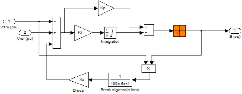
Lmax is the susceptance related to the fully inductance (the TCR connected and all the TSCs are disconnected).Figure 5. SVC – PI controller
4. Proportional Integrator (PI) SVC
Control
Due to simplest structure, easy designing and low cost, PI controller is used in SVC as voltage regulator in most industries[11].The SVC can be operated to provide reactive power control or closed-loop AC voltage control. For closed-loop AC voltage control, the line voltage, as measured at the point of connection, is compared to a reference value and an error signal is produced. This is passed to a PI controller to generate the required susceptance value (B) [24]. The SVC based PI controller is shown in fig (5)
5. Fuzzy Logic Control
Fuzzy Logic has attracted considerable attention as a novel computational system because of the variety of advantages it offers over the conventional computational systems [11]. Fuzzy logic controllers have been successfully applied to control non-linear dynamic systems [12,13] especially in the field of adaptive control by making use of on-line training. Unlike other classical control methods, such controllers are model free controllers, i.e. they do not require an exact mathematical model of the controlled system. Moreover, rapidity and robustness are the most profound and interesting properties in comparison to the other classical schemes [25]. One problem in design of a SVC for good performance is the tuning of PI controller which may not be achieved in a simplistic manner. Fuzzy controller is one of the nonlinear and robust control methods which are based on expert knowledge and there is no need to have the accurate model of the system. There are two main types of Fuzzy Logic Controllers (FLCs): Mamdani's type and Takagi- Sugeno (T-S) [24].
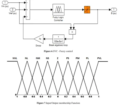
5.1. Fuzzy Logic principle to Control A SVC
Fuzzy logic can be used to develop the control laws such as the calculation of the susceptance B or in the Power
System Stabilizers (PSS). Fuzzy logic enables the formalization of the uncertainty due to a global comprehensive knowledge of a complex nonlinear system. This approach involves three basic steps: the fuzzyfication, the elaboration of the inference rules and the defuzzyfication. In this work due to the simplicity of Mamdani's model and ease of implementation in hardware, Mamdani’s type is considered in this paper. our main objective is to replace the PI regulator with a fuzzy controller in order to determine the susceptance B in the SVC device as shown in fig(6). Input/Output membership function of FLC are shown in Fig (7).
6. Studied System Description
Figure 6.SVC –Fuzzy control
[image:7.595.107.502.195.725.2]Figure 7.Input/Output membership Function
Figure 8. STUDIED SYSTEM
Table 1. DFIG parameter
Generator nominal power (MW) 1.5/0.9 Nominal phase to phase voltage (V) 575
Stator resistance (p.u.) 0.00706
Rotor resistance 0.005
Stator leakage inductance (p.u.) 0.171 Rotor leakage inductance (p.u.) 0.156 Magnetizing inductance (p.u.) 2.9
Base frequency (Hz) 60
Pairs of poles 3
Inertia constant (s) 5.04
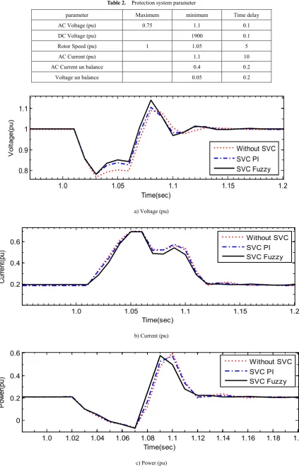
[image:7.595.112.488.433.753.2]Table 2. Protection system parameter
parameter Maximum minimum Time delay
AC Voltage (pu) 0.75 1.1 0.1
DC Voltage (pu) 1900 0.1
Rotor Speed (pu) 1 1.05 5
AC Current (pu) 1.1 10
AC Current un balance 0.4 0.2
Voltage un balance 0.05 0.2
a) Voltage (pu)
b) Current (pu)
c) Power (pu)
1.0 1.05 1.1 1.15 1.2
0.8 0.9 1 1.1
Time(sec)
V
ol
tage(
pu)
Without SVC SVC PI SVC Fuzzy
1.0 1.05 1.1 1.15 1.2
0.2 0.4 0.6
Time(sec)
Cur
rent
(pu)
Without SVC SVC PI SVC Fuzzy
1.0 1.02 1.04 1.06 1.08 1.1 1.12 1.14 1.16 1.18 1.2
0 0.2 0.4 0.6
Time(sec)
Pow
er
(pu)
d) Reactive Power (pu)
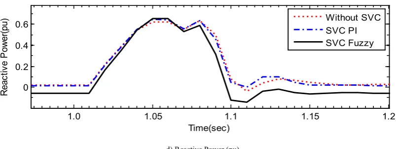
Figure 9. Studied system dynamic performance in case of single line to ground fault
7. Simulation Results
Case (1)
Single line to ground fault is occurred at bus B25 and sustain for 100ms. The effect of the SVC with the proposed FLC provides smooth and much quick response i.e. the system catch the pre fault value quickly and without any appreciable oscillation. Also, SVC based PI controller provide not bad performance as depicted in Fig. 9.
Case (2)
A double line to ground fault is occurred at bus B25 for 100 m.sec.. The system dynamic performance is as shown in Fig. 10. It is very clear that the SVC based FLC even with strong fault, it has a significant effect in damping the system oscillations very fast with less overshoot and undershoot. The fault is within the limit of the wind farm protection devices so it still is connected with the grid with or without SVC.
a) Voltage (pu)
b) Current (pu)
1.0 1.05 1.1 1.15 1.2
0 0.2 0.4 0.6
Time(sec)
Reac
tiv
e P
ow
er
(pu)
Without SVC SVC PI SVC Fuzzy
1.0 1.05 1.1 1.15 1.2
0.2 0.4 0.6 0.8 1 1.2
Time(sec)
Vol
tage(
pu)
Without SVC SVC PI SVC Fuzzy
1.0 1.05 1.1 1.15 1.2
0.2 0.4 0.6 0.8
Time(sec)
Cur
rent
(pu)
c) Power (pu)
[image:10.595.92.508.76.399.2]d) Reactive Power (pu)
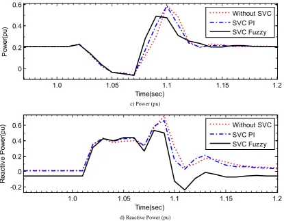
Figure 10. System dynamic response in case of Double line to ground fault Case (3)
A three line to ground fault is considered at B25 and sustained 80 ms. The simulation results show that SVC with both controller support the wind farm to be in synchronism with the grid during these sever disturbance. But the system without SVC could not support the system i.e. the protection devices disconnect the wind farm. The proposed controller provides better damping performance, lower oscillation and fast response as depicted in Fig. 11.
a) Voltage (pu)
1.0 1.05 1.1 1.15 1.2
0 0.2 0.4 0.6
Time(sec)
P
ow
er
(pu)
Without SVC SVC PI SVC Fuzzy
1.0 1.05 1.1 1.15 1.2
-0.2 0 0.2 0.4 0.6
Time(sec)
R
eac
tiv
e P
ow
er
(pu) Without SVCSVC PI
SVC Fuzzy
1.0
1.05
1.1
1.15
1.2
1.25
1.3
1.35
0.2
0.4
0.6
0.8
1
1.2
Time(sec)
V
ol
tage(
pu)
b) Current (pu)
c) Power (pu)
d) Reactive Power (pu)
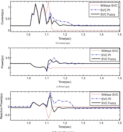
Figure 11. System dynamic response in case of three line to ground fault Case (4)
Different fault duration have been considered in case of three line to ground fault at bus B25 with 50ms, 80ms and100ms durations respectively with the proposed FLC control system. With increasing fault duration system oscillation increased and the system response is slower. At fault duration 100ms the system could not support the wind farm any more, The system protection trip out and disconnect the wind farm from grid as shown in Fig . 12.
a) Voltage (pu)
1.0 1.1 1.2 1.3 1.4 1.5
0 0.5 1
Time(sec)
C
ur
rent
(pu)
Without SVC SVC PI SVC Fuzzy
1.0 1.1 1.2 1.3 1.4 1.5
0 0.5 1
Time(sec)
P
ow
er
(pu)
Without SVC SVC PI SVC Fuzzy
1.0 1.1 1.2 1.3 1.4 1.5
-0.5 0 0.5
Time(sec)
R
eac
tiv
e P
ow
er
(pu) Without SVCSVC PI
SVC Fuzzy
1.0 1.05 1.1 1.15 1.2 1.25
0 0.5 1
Time (sec)
Vol
tage(
pu)
[image:11.595.91.509.72.519.2]b) Current (pu)
c) Power (pu)
d) Reactive Power (pu)
Figure 12. System dynamic response in case of different fault duration Case (5)
The effect of SVC location on the system performance is investigated under three line to ground fault 80ms with SVC connected at wind farm and SVC connected at B25. The simulation results show that when the SVC is near the wind farm it provides better performance as shown in fig (13).
a) Voltage (pu)
1.0 1.05 1.1 1.15 1.2 1.25
0 0.5 1
Time (sec)
Cur
rent
(pu)
50ms 80ms 100ms
1.0 1.05 1.1 1.15 1.2 1.25
0 0.2 0.4 0.6
Time (sec)
Pow
er
(pu)
50ms 80ms 100ms
1.0 1.05 1.1 1.15 1.2 1.25
-0.5 0 0.5
Time (sec)
Reac
tiv
e P
ow
er
(pu) 50ms80ms
100ms
1.0 1.05 1.1 1.15 1.2 1.25
0.2 0.4 0.6 0.8 1 1.2
Time(sec)
Vol
tage(
pu)
[image:12.595.94.511.72.516.2]b) Current (pu)
c) Power (pu)
d) Reactive Power (pu)
Figure 13. System dynamic response when SVC has different Location
8. Conclusions
This paper introduces the effect of static VAR compensators SVC based fuzzy logic control to wind farms system connected to utility grid. The proposed approach is applied successfully to the wind farms system connected to utility grid in case of abnormal conditions. Different types of faults have been considered to evaluate the effectiveness of the proposed approach in damping the system oscillations very fast with better control quality. Single line to ground fault, double line to ground fault, and different fault duration have been considered. The proportional plus integral (PI) control is implemented for the comparative study between the effectiveness of the proposed FLC based SVC and PI based SVC. The time simulations prove the effect of the proposed SVC based FLC control over the SVC based PI
controller.
REFERENCES
[1] Hinrichsen, E. N. ; Nolan, P. J "and Stability of Wind Turbine Generators",IEEE Power Engineering Review, Vol. PER-2, Issue, 8, (1982), pp. 38-39.
[2] Hinrichsen, E.N. ; Nolan, P.J., "Dynamics and Stability of Wind Turbine Generators", IEEE Transactions on Power Apparatus and Systems, Vol. 101, Issue, 8, 1982, pp. 2640-2648
[3] Borodulin, Mikhail Y., "Effect of wind variation on wind turbine generator dynamics in power system planning stability studies", IEEE PES T&D Conference and Exposition,
1.0 1.05 1.1 1.15 1.2 1.25
0 0.2 0.4 0.6 0.8 1
Time(sec)
Cur
rent
(pu)
Wind Farm Side B25 Side
1.0 1.05 1.1 1.15 1.2 1.25
0 0.2 0.4
Time(sec)
Pow
er
(pu)
Wind Farm Side B25 Side
1.0 1.05 1.1 1.15 1.2 1.25
-0.4 -0.2 0 0.2 0.4 0.6
Time(sec)
R
eac
tiv
e P
ow
er
(pu)
[image:13.595.93.517.73.535.2]2014, pp. 1-5.
[4] Miller, N.W. ; Sanchez-Gasca, Juan J. ; Price, W.W. ; Delmerico, R.W., "Dynamic modeling of GE 1.5 and 3.6 MW wind turbine-generators for stability simulations", IEEE Power Engineering Society General Meeting, 2003, Vol., 3, pp. 1977-1983.
[5] Melicio, R. ; Mendes, V.M.F. ; Catalao, J.P.S., "Dynamic stability of wind turbines with permanent magnet machines and power-electronic converters", 9th Int. conf. on Power Engineering, Energy and Electrical Drives, 2009. POWERENG '09. pp. 484 - 489
[6] Bingsen Wang ; Venkataramanan, G., "Dynamics and stability of matrix-converter based permanent magnet wind turbine generator",
38th Annual Conference on IEEE Industrial Electronics Society IECON 2012, pp. 6069-6075.
[7] Jiajia Ren ; Yinghong Hu ; Jianze Wang ; Yanchao Ji, " Principles of low voltage-ride through ability realization of fixed speed wind generator using series reactor and SVC" 7th International Power Electronics and Motion Control Conference, 2012, Vol. 3, pp.2173-2177.
[8] Molinas, M. ; Suul, J.A. ; Undeland, T. "A simple method for analytical evaluation of LVRT in windenergy for induction generators with STATCOM or SVC" European Conference on Power Electronics and Applications, 2007, pp. 1-10. [9] Ahmed, T., Noro, O., Matzuo, K., Shindo, Y., Nakaoka, M.,
"Minimum excitation capacitance requirements for windturbine coupled stand-alone self-excited induction generator with voltage regulation based on SVC" The 25th International Telecommunications Energy Conference, 2003, pp. 396-403.
[10] Le, C.D. ; Bollen, M.H.J. "Ride-through of induction generator based wind park with switched capacitor, SVC, or STATCOM", IEEE Power and Energy Society General Meeting, 2010, pp. 1-7.
[11] Ahmed, T. ; Ogura, K. ; Soshin, K. ; Hiraki, E. ; Nakaoka, M. ,"Small-scale wind turbine coupled single-phase self-excited induction generator with SVC for isolated renewable energy utilization", The Fifth International Conference on Power Electronics and Drive Systems, (2003), Vol. 1, pp. 781-786.
[12] Molinas, M. ; Suul, J.A. ; Undeland, T., "Low Voltage Ride Through of Wind Farms With Cage Generators: STATCOM Versus SVC",
IEEE Transactions on Power Electronics, Vol., Issue 3, (2008), pp. 1104-1117.
[13] K. E Okedu."A Study of Wind Farm Stabilization Using DFIG or STATCOM Considering Grid Requirements" Journal of Engineering Science and Technology, 3, 2010, PP. 200-209.
[14] Mehrdad Ahmadi Kamarposhti, Mostafa Alinezhad. "Comparison of SVC and STATCOM in Static Voltage Stability Margin Enhancement" International Journal of Electrical and Electronics Engineering, Vol. 4, No. 5,2010, PP. 323-328.
[15] Roopesh Kumar, Ashish Choubey." Voltage Stability
Improvement by using SVC with Fuzzy Logic Controller in Multi-Machine Power System" International Journal of Electrical and Electronics Research, Vol. 2, No. 4, 2014, PP. 61-66.
[16] K. . L. Lo, Laiq KHAN. "Fuzzy logic based SVC for power system transient stability enhancement" Electric Utility Deregulation and Restructuring and Power Technologies, Proceedings. DRPT. International Conference on. IEEE, 2000, PP. 453-458.
[17] MANSOUR, Ibrahim, et al. "Fuzzy logic control of a SVC to improve the transient stability of ac power systems" Industrial Electronics, IECON'09. 35th Annual Conference of IEEE. 2009, PP. 3240-3245
[18] I smail K, Said and Marouf Pirouti. "Neural network-based load balancing and reactive power control by Static VAR compensator" International Journal of Computer and Electrical Engineering, Vol. 1, No. 1, April 2009, PP. 25-31. [19] S. Sabna, D. Prasad, R. Shivakumar. "Power System Stability
Enhancement by Neuro Fuzzy Logic Based SVC for Multi Machine System" International Journal of Engineering and Advanced Technology (IJEAT),Vol. 1, No.4, April 2012, PP. 207-2011
[20] Gilsung Byeon, In Kwon Park, Gilsoo Jang. "Modeling and control of a doubly-fed induction generator (DFIG) wind power generation system for real-time simulations" Journal of Electrical Engineering and Technology, Vol. 5, No.1, 2010, PP. 61-69.
[21] Ezzeldin S. Abdin, Wilson Xu. "Control Design and Dynamic Performance Analysis of a Wind Turbine-Induction Generator Unit" Energy Conversion, IEEE Transactions, Vol. 15, No.1, 2000, PP. 91-96.
[22] SINGH, Bindeshwar." Introduction to FACTS Controllers in Wind Power Farms: A Technological Review" International Journal of Renewable Energy Research (IJRER), Vol. 2, No. 2, 2012, PP. 166-212.
[23] LIMA, Francisco KA, Et Al. "Rotor Voltage Dynamics in the Doubly Fed Induction Generator during Grid Faults" Power Electronics, IEEE Transactions, Vol. 25, No.1, 2010, PP. 118-130.
[24] MITHULANANTHAN, Nadarajah, et al. "Comparison of PSS, SVC, and STATCOM controllers for damping power system oscillations" Power Systems, IEEE Transactions, Vol. 18, No. 2, 2003, PP. 786-792.
[25] Tamer ABDELAZIM, O. P. MALIK. "Intelligent SVC control for transient stability enhancement" Power Engineering Society General Meeting, IEEE, 2005, PP. 1701-1707
[26] M. AZOUZ, et al." Fuzzy logic control of wind energy systems" Proceedings of the 14th International Middle East Power Systems Conference (MEPCON’10), Cairo University, Egypt, 311, December 2010, PP. 935-940.