Combined Method of Spring-forward and Spring-back
for Die Compensation Acceleration
Agus Dwi Anggono
1, Waluyo Adi Siswanto
2, Badrul Omar
21
Department of Mechanical Engineering
Universitas Muhammadiyah Surakarta
Jl. A. Yani PO.BOX I Pabelan, 57102
Sukoharjo - Jawa Tengah
INDONESIA
2
Advenced Dynamics and Vehicle Safety (AdVeS)
Department of Engineering Mechanics
Universiti Tun Hussein Onn Malaysia
86400 Parit Raja - Batu Pahat
MALAYSIA
[email protected]
Abstract
The most key factor in the modern sheet metal process is an accurate dimension of final shape part. The accurate simulation of the drawing products will not be useful since springback will occur after the tools are removed off the drawing die set. One of the most promising ways to solve this problem is modify the die surface as known die compensation. Die compensation is one of the hottest topics in the stamping field.
In this paper, a new method to compensate the die tool shape due to elastic deviation is proposed. The combination of spring-forward and spring-back method is applied simultaneously. This method was applied to 2D draw bending benchmark problem from Numisheet ’93 for verification. The simulation result show that the final deformed part is closely to the desired shape part.
1. Introduction
Springback is often an important part of a forming analysis because the springback analysis determines the shape of the final, unloaded part. Springback in a stamping process is due to the elastic deformation of the part during removing off the tools. Control of springback is very important in the automotive industry because the high strength steels and aluminum alloys are increasingly used. Modern finite element (FE) codes for sheet metal forming simulation have been shown to be able to produce excellent results regarding the springback prediction [1-3]
.
Springback can be predicted accurately by using modern finite element codes for sheet metal forming simulation [4], but there still remains the problem of how to apply the results to appear at a suitable die design to produce a target part shape. Accordingly, it is very crucial to compensate for springback errors by modifying the shape of stamping tools. Tools shape modification due to springback errors is very complex process. There are two methods commonly used to modify die tools, the trial-and-error and FE method. The trial-and-error method was done in the past which is a
time consuming and cost-prohibitive process. Many years of die tools making experience are necessary before an engineer can successfully guess how to modify tools shape.
FE method based on computer simulation has gained popularity in sheet metal forming because of its speed and low cost, and it has been proven to be effective in formability and springback prediction [5]. There are two methodologies used to realize the geometric compensation of springback. They are the so-called spring-forward compensation and spring-back compensation. Both are based on an iterative procedure. Spring-back (SB) compensation as known Displacement Adjustment (DA) method is based on geometrical approach, to move the nodal opposite to springback error. The displacements of vectors at each node are used to adjust the trial die shape until the target shape is achieved. Spring-forward (SF) method of Karafillis and Boyce (K&B) is based on numerical simulation as well by using Finite Element Analysis (FEA). This method applied inverse residual stresses that are recorded during loading to the formed part [6].
2. Die Compensation
2.1 Spring-back Method
Until recently, accurate springback prediction was only available for pure bending via empirical handbook rules or simple analysis, and for a few other specialized two dimensional geometries [7-8]. When sheet metal is formed, the stamping tools bends the metal into certain angle with a given bend radius. Once the tool is removed, the metal will spring back, widening the angle and increasing the radius as shown in Fig. 1.
The length of the mid-surface is
(1) This will remain unchanged during unloading as the
stress and strain at the middle surface are zero. From this, we obtain
(2)
Differentiating Equation 2, in which l = constant, we obtain
∆ ∆
(3) The assumed stress–strain curve for an elastic, perfectly
plastic material that undergoes reverse loading is shown in Fig. 2. From Fig. 2, a change in stress of Δσ1 = −2S
can occur without the material becoming plastic. Assume that the unloading of the sheet will be an elastic process, than the elastic bending equations can be written in difference form, i.e.
∆ ∆ ∆
[image:2.595.325.522.312.499.2]/ ∆ (4)
[image:2.595.57.283.386.535.2]Fig. 1: Loading and unloading a sheet that has been bent by a moment without tension
Fig. 2: Elastic, perfectly plastic material model with reverse loading.
2.2 Spring-forward Method
The first loading step in sheet metal forming is the operation where a punch is moving into an original die in order to form a blank material, whereas during the unloading step the punch and the formed part are released from the dies. Because of an elastic recovery of the material, part dimensional is changed which happens during unloading, known as springback error.
Spring-forward method applied the inverse residual stresses acting on the part sheet [9] which are recorded by FE during the loading process.
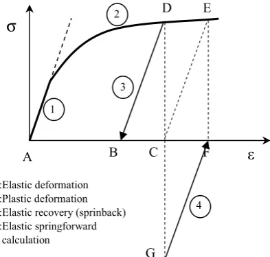
[image:2.595.68.272.585.724.2]The illustration of die modification by following spring forward result is shown in Fig. 3. Blank sheet is deformed to the original die which is represented as point C. After the part has been plastically deformed to point C, however the part shape will deviate from the target due to elastic recovery to the point B. By applying inverse residual stress to the formed part, a new target shape is point F. Then, after elastic recovery the final part will be recovered to the point C, same as the original target shape.
Fig. 3: Springforward optimization strategy
2.3 Combination SB and SF Method
Combination SB and SF is applied the displacement adjustment and inverse residual stress in the die compensation calculation algorithm. The first iteration conducted by SB method by added the total recovery (error) to the current shape nodal position, obtaining new tooling shape of FE or die tool surface generator. For the second cycle, a blank sheet is deformed to this new tooling surface, then, after elastic recovery, the final shape is compared to the reference surface as well, if the error out of the tolerance then the SF method is conducted.
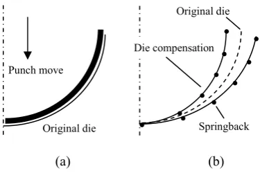
During loading, the internal stress is recorded as result of FE. This inverse stress is applied to deformed surface by SF method and obtained a new tool surface. Die compensation illustration is shown in Fig. 4, the first step of sheet metal forming by using original die shape is illustrated in 4(a). Figure 4(b) is illustration of die compensation due to springback deviation by inverting the point displacement or residual stress.
σ
ε
A B C F D E
G
1
2
3
4 1:Elastic deformation
2:Plastic deformation 3:Elastic recovery (sprinback) 4:Elastic springforward calculation
M θ M (θ+Δθ)
(a) (b)
Fig. 4: Die optimization illustration
3. Analysis Procedure
3.1 Assembly Model
Sheet metal forming simulations conducted by using 2D model assembly which are consist of punch, holder, die and blank sheet. Model design, geometry dimension and assembly position are adopted from Numisheet ’93 benchmark problem, as shown in Fig. 5.
[image:3.595.73.261.81.206.2]In this analysis, the main observation is focused on the blank sheet because of the die compensation is based on springback deviation acting on the blank sheet. Blank is defined as deformable solid part with planar shell feature whereas the punch, holder and die are represented as analytical rigid part with wire base feature.
Fig. 5: 2D assembly model of die draw (in mm).
The punch is control at a constant 4.3 m/s and the blank holder force (BHF) is varied from 100, 200, 440, 650 and 800kN. Coefficient of friction between blank, holder and die is 0.3 whereas between punch and blank is frictionless.
3.2 Blank Sheet Material Properties
Many metals have approximately linear elastic behavior at low strain magnitudes and the stiffness of the material, known as the Young's or elastic modulus, is constant. At higher stress and strain magnitudes, metals begin to have nonlinear, inelastic behavior, which is referred to as plasticity.
The strain hardening of materials in this analysis is modeled by anisotropic hardening rule which is widely adopted in predicting purely elastic springback. Thickness, friction coefficient, yield strength and rolling direction are shown in Table 1.
Table 1. Material Properties
Material type HX260LAD Thickness 1.0 mm
Rolling direction Parallel to global x Frictional coef. 0.13
Poisson’s ratio 0.3 Young’s ratio 210 MPa Yield strength 176 MPa
HX260LAD steel sheet is selected as the blank material in our study. This type is micro-alloyed steel grades with high yield strength for cold forming according to DIN EN 10346 / DIN EN 10143. Characteristic of these steels is the minimum and maximum values of yield and tensile strengths and the minimum values of elongation. High strength formable, zinc-iron coated steels manufactured using oxygen blowing process, are aluminum killed sheet steel. Applications of these steels are usually in automotive components, furniture and domestic appliances.
4. Results and Discussions
4.1 Effect of Blank Holder Force (BHF)
[image:3.595.62.267.412.580.2]In this study, the influences of the BHF on springback deviation have been investigated through FE method. The variations of BHF are 200, 440, 650 and 800 kN. The result of springback is shown in Fig. 6 which the lowest deviation is BHF 200kN. In this analysis, the blank is meshed by using quadrilateral element type. The numbers of element are 400 elements that seeds parts are controlled by edges where the horizontal side is divided by 100 and the thickness is divided by 4.
Fig. 6: The influence of BHF on springback error.
Punch move
Original die
.
.
.
.
.
.
.
.
.
.
.
Springback Original die
Die compensation
[image:3.595.312.539.529.712.2]Fig. 7: Lower BHF is not always decreased the springback error.
The lowest springback is due to apply of lower BHF. According to this result, then analysis is continued by applying of BHF 100kN for verification and the result shows that springback error is higher than the previous (BHF 200kN) as shown in Fig. 7 and by applied lower BHF is not always decreased the springback. The ideal BHF is within force 200 kN. Halil et al. [10] have been investigated the influences of BHF on wall thickness with the variations of 3, 4, 6, 10, 13, 15, and 25 MPa which is the ideal pressure within the 5-8 range.
4.2 Effect of Element Number
[image:4.595.66.252.74.136.2]Bending simulation accuracy has been well verified for the simulation in flat regions, in which the relative curvature (t/R) is smaller than 1/6 where t is sheet thickness and R is internal bend radius. The investigation of the effect of number element in accuracy of springback calculation is done by using element number in 200 and 400 elements. Fig. 8 shows tendency of calculated springback varying with number of element, which can verify that a larger number element will result improve accuracy of calculated springback. However, the calculated error cannot be neglected in small bending (t/R > 1/6) [11] where the linear shape function is insufficient.
Fig. 7: The influence of element number to the springback error.
4.3 Simulation of Die Compensation
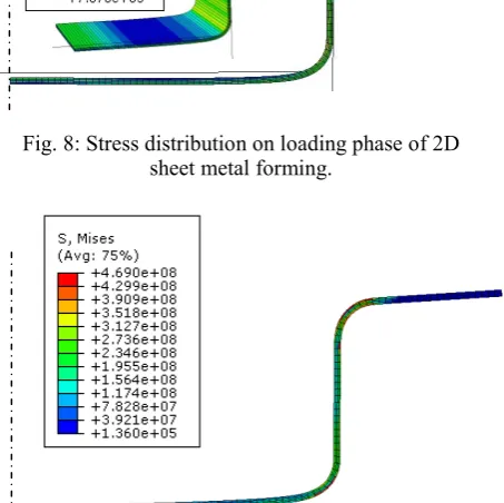
2D sheet metal froming of Numisheet ’93 benchmark problem was chosen as the assembly model because of its simplicity. ABAQUS Explicit was used in FE simulation. Punch, holder, die and deformed sheet at loading condition are illustrated in Fig. 8. This tooling geometry has a symmetry plane at x=0. Sheet metal of HX260LAD is used in this simulation which the properties are explained above. Punch pressure magnitude is 1000 Pa that produces a force on the blank three orders of magnitude lower than BHF.
After loading phase the next step is unloading as a springback calculation. Springback calculation is conducted by ABAQUS Implicit which is imports all analysis data from the explicit platform such as stress, strain etc. Since springback analyses are static
[image:4.595.309.535.100.237.2]simulations without external loading or contact. The unloading phase is shown in Fig. 9.
Fig. 8: Stress distribution on loading phase of 2D sheet metal forming.
Fig. 9: Stress distribution on unloading phase of 2D sheet metal forming.
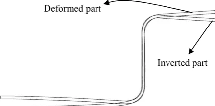
The unsuitable part to the target is happened after unloading and the comparison to the target shape is seen in Fig. 7. This node position is then converted to the ASCII (American Standard Code for Information Interchange) data as point coordinate. The ASCII data is read by CATIA to generate inverse position which the axis of deformed part is as reference of transformation. This step is used spring-back algorithm based on geometrical method, to move the surface nodes in the direction opposite springback error [12] as shown in Fig. 10.
The first die compensation was conducted by CATIA. The new die shape is then exported to ABAQUS explicit to be used in the next simulations. The blank sheet is deformed to the new die shapes. Loading process at the first cycle by using compensate die is shown in Fig. 11.
After loading step by using new die shape, the punch and formed part are released from the die. Residual stresses are recorded by FE during unloading step. After the part has been deformed, the new position of the part shape is already much closer to the reference geometry, as shown in Fig. 12.
The residual stresses that are recorded by FE are applied to deformed part in inverted direction. By applying inverted residual stresses (spring-forward method) to the formed part, a new compensate die is
100 kN 200 kN Target
200 elements
400 elements
[image:4.595.311.538.188.414.2]obtained. By using this new die shape, the simulation of springback is done anymore, then, after unloading, the final shape is the same as the target as shown in Fig. 13.
Fig. 10: Curve is created from ASCII data
[image:5.595.61.281.129.237.2]Fig. 11: Blank sheet metal is deformed by using compensate die.
Fig. 12: Unloading formed sheet is much closer to the reference geometry.
Fig. 13: Unloading formed sheet is elastic recovered to the reference geometry.
5. Conclusions
The underlying scope of the present work has been to outline a finite element technique for predicting springback deformations compensation in sheet metal forming. In this paper, the influences of element numbers and BHF have been coupled to analyze the springback error has done successfully.
A method for the die compensation of sheet metal forming dies due to springback has been developed. The spring-back method (SB) is an iterative technique based on comparing a target part shape with a formed-and-unloaded part shape simulated using finite elements. In contrast, the spring-forward (SF) method in the sheet metal forming applied the inverted stress makes use of FE-simulated forces for a similar iterative procedure. Combine this two methods have successful to simulate die compensation in 2D forming model.
6. Acknowledgement
The authors would like to thanks to Universiti Tun Hussein Onn Malaysia (UTHM). This work has been conducted under Advance Dynamic and Vehicle Safety (AdVeS) research group. Part of the work has been supported by Fundamental Research Grant Scheme (FRGS) Vot No.0557 and Vot. No. 0748.
References
[1] Siswanto, W. A., Omar, B., Anggono, A. D., Mathew, A. A., “Springback Behavior Prediction of Benchmark Problem II Numisheet 2008 Model Under Smooth Drawbead”, Proceeding of the NAMME2010, (2010), pp. 197-203.
[2] Li, K. P., Carden, W. P., Wagoner, R. H., “Simulation of Springback”, International Journal of Mechanical Science, Vol. 44, (2002), pp. 103-122. [3] Panthi, S. K., Ramakrishnan, N., Pathak, K. K., Chouhan, J. S., “An Analysis of Springback in Sheet Metal Bending Using Finite Element Method (FEM)”, Jounal of Materials Processing Technology, Vol. 186, (2007), pp. 120-124.
[4] Chenga, H. S., Caoa, J., Xiab, Z. C., “An Accelerated Springback Compensation Method”, International Journal of Mechanical Science, Vol. 49, (2007),pp. 267-279.
[5] Cao, J., Yao, H., Karafllis, A. P., Boyce, M. C., “Prediction of Localized Thinning in Sheet Metal
Using A General Anisotropic Yield Criterion”, International Journal of Plasticity, Vol. 16, (2000), pp. 1106-1129.
[6] Siswanto, W. A., Omar, B., “Die Surface Design Optimization Accommodating Springback Assisted by an Automatic Surface Generator”, International Journal of Material Forming, Vol. 2, (2009), pp 797-800.
[7] Marciniak, Z., Duncan, J. L., Hu, S. J., “Mechanics of Sheet Metal Forming”, 2nd edition, Butterworth-Heinemann, 2002.
[8] Hosford, W. F., and Caddel, R. M., “Metal Forming Mechanics and Metallurgy”, 3rd edition, Cambridge
University Press, 2007.
[9] Gan, W., Wagoner, R. H., “Die Design Method for Springback”, International Journal of Mechanical Science, Vol. 46, (2004), pp. 1097-1113.
Reference of upper position
Reference of upper position Deformed part
[image:5.595.57.278.489.712.2][10] Halil, I., D., Esner, C., Yasar, M., “Effect of the blank holder force on drawing of aluminum alloy square cup: Theoretical and experimental investigation”, Journal of Processing Material Technology, Vol. 206, (2008), pp. 152-160.
[11] Li, K., Wagoner, R. H., “Simulation of springback. In: Huetink J, Baaijens FPT (eds) Simulation of Materials Processing: Theory, Methods and Applications”, Proceedings of the 6th International Conference on NUMIFORM 1998, Enschede, (1998), pp. 21–31.