ISSN 2250-3153
Increasing cost efficiency through minimizing
transformer losses: Design and performance analysis of a
250 kVA off-load tap changing step down transformer
Sairatun Nesa Soheli1, Md Saidul Hasan2, Md Refat Uddin3
1,3
Dept of EEE, IUBAT–International University of Business Agriculture and Technology
2
Dept of EEE, Northern Science and Technology
DOI: 10.29322/IJSRP.8.9.2018.p8188
http://dx.doi.org/10.29322/IJSRP.8.9.2018.p8188
Abstract- A step down transformer can decrease the voltage level and increase the current level by keeping constant power and frequency which gives needful output to a substation. To get this require output transformer design should be splendid. This paper based on transformer design and analysis which can reduce copper and core losses with proficient cost. Step lop core lamination reduce no load voltage up to 8% no load current up to 50% with low noise level. Payback analysis will give the comparison between proposed designed transformer and normal designed transformer. For example: The electrical bill per year due to losses is around 1, 25, 356 bdt for proposed designed transformer rather than the normal transformer where the electrical bill per year due to losses is around 2, 34, 943 bdt and thus yearly saving due to energy efficient transformer is (2, 34, 943 - 1, 25, 356) = 1, 09, 587 bdt. By this way the huge amount of money will be saved by the consumer.
Index Terms- Design, inner connection, analysis, core design, payback analysis
I. INTRODUCTION
Before to start with a working design, a brief requirement of a 250 kVA, 11/0.415 kV copper-wound transformer has been conceived. The first step of the design is to select the number of turns of coils and continue further in the direction of estimating the coil construction, up to arriving at the window height of the core frame. Based on the calculated window height, the design of the secondary coil is done. After that, core diameter, limb center, step width, core stack, core area, flux density are calculated with the obtainable design output. The next step of design is the configuration of coils and limb center of the core frame. Based on the window height and limb center of the core frame, detailed design of core up to the weight of the absolute set of cores is estimated [1]. Manufacturing details of low and high voltage windings, placement of coils, internal clearances tapping and weight of conductor are done. Next step is that, calculation of performance figures. The procedure of calculation of resistance, ratio error, efficiency, losses, no-load current, percentage impedance, regulation have been dealt with. After the design of interior active part, the chapter has enclosed the process of tank design with different types of radiators. A small number of paragraphs have been added to established the procedure of designing the core frame part, core stud, tie rod, conservator etc. After that calculation of oil volume, overall weight and dimensions has also been discussed. The chapter ends with the procedure of filling up the guaranteed technical particulars with applicable calculation of performance parameters and generation of various drawings for submission. The thermal ability to withstand an external short-circuit has also been shown [2].
II. METHODOLOGY
Determined number of turns of low and high tension side with core calculation
Tap changer connected with high tension copper winding and determine the terminals of low and high tension side [3]
Setting of two terminal by tap cover with initial testing
III. SPECIFICATIONS OF THE PROPOSED TRANSFORMER
Rating 250 kVA; oil cooled
No-load voltage ratio 11000/415
No. of phase 3 Phase
Frequency 50 Hz
Winding material Electrolytic copper
Tapping’s on HV ± 2% to ± 8% (off circuit)
No. load/load loss 450/2610 watt
Impedance 5.5%
Flux density 1.6 Tesla (max)
Current density 2.6 A/sq. mm (max)
Connection Delta/star, vector group Dyn 11
Temperature rise 45/75°C
Other specifications as per IS-2026
High Tension (HT) = 11000 V
Low Tension (LT) = 415 V
Let, Current at low tension side, ILT = 347.80 Amp
Let, Current at high tension side, IHT = 13.12 or 7.58 Amp
IV. BLUEPRINT OF THE PROPOSED TRANSFORMER
Copper is connected with high and low tension coil as well as the connection of high tension tapping diagrammatic concept given below:
S
F S
F S
F Core
Winding
Tap changer
[image:2.612.77.526.353.506.2]1 2 3 4
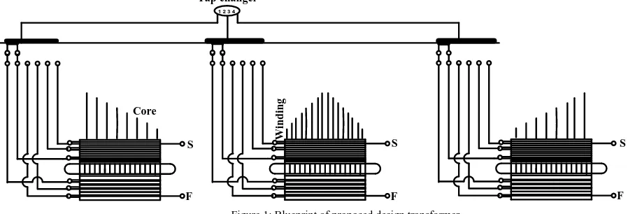
Figure 1: Blueprint of proposed design transformer
Here, 250 kVA of load tap changing transformer which have 5 tapping and here tapping 2 is the standard tapping position of the transformer. In this taping 2 position we get the standard output result of transformer. High tension copper has to be connected with two parts in per phase because of proper oil circulation [4]. We can see that core is surrounded by the low tension coil and then this low tension coil is surrounded by the high tension coil. High tension coil connected with delta ways and low tension coil connected with star ways. For tapping purpose here the high tension coil starting part indicate by `S` and finishing part of the coil indicate by `F`. The first tapping start and finish are shorted that’s why all winding are become connected and the result is that we get minimum voltage as an output in low tension side. Again the 5th tapping position the minimum winds are connected in a low tension side and thus we get maximum voltage as an output result on low tension side of a transformer [5].
V. PERFORMANCE ANALYSIS OF THE PROPOSED TRANSFORMER
A. LOW TENSION (HT) COIL CALCULATION
Connection: Star
Per turn voltage, (V/T) = (1 ÷ C) * �(kVA∗1000) ÷ 3 ………..(1) Here coefficient, C = 40 and kVA = 250
Now from equation (1);
(V/T) = (1 ÷ 40) * �(250∗1000) ÷ 3 = 7.21688 V
ISSN 2250-3153
Number of turn per phase, T = (voltage per phase ÷ per turn voltage) = (239.6004 ÷ 7.21688) = 33.2 Number of turn of low tension side = 33.2 * √3 = 58
B. HIGH TENSION (HT) COIL CALCULATION
Connection: Delta Copper type: Bare Number of parts = 4
Per turn voltage, (V/T) = (1 ÷ C) * �(kVA∗1000) ÷ 3 ……….. (2) Here, coefficient, C= 40 and kVA = 250
Now from equation (1);
(V/T) = (1 ÷ 40) * �(250∗1000) ÷ 3 = 7.21688 V
Voltage per phase, Vp = (high tension voltage ÷ √3 ) = (11000 ÷ √3 ) = 6350.85 V Number of turn per phase, T = (voltage per phase ÷ per turn voltage)
= (6350.85 ÷ 7.21688) = 879.99 Number of turn of high tension side = 879.99 * √3≈1524
C. IRON CORE CALCULATION
Core area Ai = 4Per.44turn∗f∗Bmvoltage∗0.92 Here, Frequency, f = 50 Hz Flux density, Bm = 1.57
So, Ai = 0.022507 m2 = 22506.7 mm2 Again, Core Ai= πD2 / 4
So, πD2
/ 4 = 22506.7 Diameter, D = 169.324 mm
Table 1: Usable core diameter rating
Core Diameter 163 mm
Number of turn in low tension side 32 T Number of turn in high tension side 800 T
D. DETERMINE OF LOW TENSION COPPER SIZE:
Current at low tension side, ILT = 347.80 Amp Copper current density = 2.89 Amp/mm2 (std)
Required cross section area = CurrentCopperatcurrentlowtension densityside = 3472.89.80 = 120 mm2
Now, 9 * 3.5 mm copper may be used for low tension coil with damp proof course (DPC) is 9.5 * 4.0 Determination of inner diameter (IO), outer diameter (OD), axial length (A/L) of low tension coil; Core diameter (D) = 163 mm
Inner diameter (ID) = (D + press. thickness * 2) = 170 mm
Outer diameter (OD) = (ID + 2 * low tension radial depth) = 206 mm Axial length (A/L) = [(T’ * NT) * (Totalnumberofturn
L )] + [(T’) + Pressboard width min] Axial length of low tension A / LLT = 360 mm
E. DETERMINE OF HIGH TENSION COPPER SIZE
Current at high tension side, IHT = 7.58 Amp
Copper Size (mm) No of wire along depth
No of wire along depth
Area (mm2) A = 126 mm2
Width
Width Thickness
Height
Copper current density δ = 2.89 Amp/mm2 (std)
Required cross section area = Currentathightensionside Coppercurrent density =
7.58
[image:4.612.212.432.508.627.2]2.89 = 2.621 mm 2
Table 2: Copper size and area
Copper size Area
Diameter(SWG) Diameter (mm) ATH (mm2)
14 2.03 3.2349065
SWG is Standard Wire Gauge = 14 used for high tension coil Damp proof course (DPC) copper size = 2.1 mm
Damp proof course (DPC) thickness = 0.07 mm Here, (11000 * √3) / 415 = 45.910
Number of turn of high tension side = 1524
Determination of inner diameter (IO), Outer diameter (OD), Axial length (A/L) of high tension coil; Total axial length, (A/L)HT,T = [(A/L)LT – gap for part coil] = 322 mm
Single axial length, (A/L)HT,S =
(A/L) HT,T
noofparts= 80.5 mm So, per layer turn, Tp = total(Acopper/L) HT,Tsize = 38
Total calculated layer = turnpercoil
Tp = 9.8217391
In practical no of layer = 10
Inner diameter (ID) = low tension outer diameter + gap between low tension and high tension coil = 245 mm
High tension outer diameter (OD) = inner diameter + (total copper wire diameter * 2 * no of layer) + oil duct (0) + leatheroid paper (5) = 292 mm
Axial length (A/L)HT,S = 80.5 mm
F. OVERALL CORE DESIGN OF 250 KVA STEP DOWN TRANSFORMER
Axial length, (A/L)LT = 360 mm
Window wide and height (W/H) = (A/L)LT + clearance = 360 + 25 = 385 mm Core diameter, D = 163 mm
1st stack = 30 mm Core width = 160 mm
P to P distance = high tension outer diameter + clearance = 292 + 10 = 302
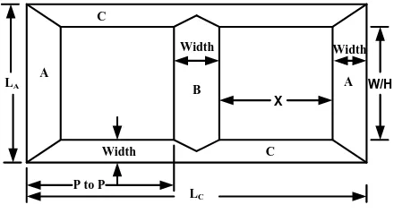
A Core length, LA = (window wide and height + 2 * core width) = (385 + 2 * 160) = 705 mm B Core length, LB = (window wide and height + core width) = (385 + 160) = 545 mm C Core length, LC = (2 * P to P distance core + core width) = 746 mm
X = [C core length, LC – (3 * core width)] / 2 = [746 - (3 * 160)] = 142 mm
P to P
LC
LA W/H
A C
A B
Width C
X
Width Width
Figure 1: Limbed Core PART A
ISSN 2250-3153
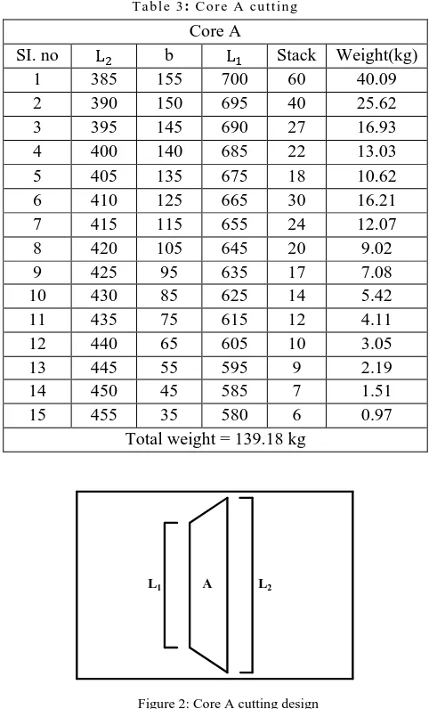
T a b l e 3: C o r e A cu t t in g Core A
SI. no L2 b L1 Stack Weight(kg)
1 385 155 700 60 40.09
2 390 150 695 40 25.62
3 395 145 690 27 16.93
4 400 140 685 22 13.03
5 405 135 675 18 10.62
6 410 125 665 30 16.21
7 415 115 655 24 12.07
8 420 105 645 20 9.02
9 425 95 635 17 7.08
10 430 85 625 14 5.42
11 435 75 615 12 4.11
12 440 65 605 10 3.05
13 445 55 595 9 2.19
14 450 45 585 7 1.51
15 455 35 580 6 0.97
Total weight = 139.18 kg
A
L1 L2
Figure 2: Core A cutting design PART B
Length of lamination, L is calculated as (W/H + W) mm; where W/H and W are in mm Similarly, weight is calculated as = (L – 1/2 W) * W * core stack * density * 0.97 *10−3 kg Where L, W and core stack are in cm
T a b l e .4 : C o r e B cu tt in g Core B
SI. no L2 b L1 Stack Weight(kg)
1 385 155 454 30 17.10
2 390 150 454 19.77 10.98
3 395 145 454 14 7.30
4 400 140 454 11 5.65
5 405 135 454 9 4.63
6 410 125 454 15 7.14
7 415 115 454 12 5.37
8 420 105 454 10 4.14
9 425 95 454 8 3.21
10 430 85 454 7 2.49
11 435 75 454 6 1.90
[image:5.612.185.426.59.457.2] [image:5.612.182.430.541.740.2]14 450 45 454 4 0.72
15 455 35 454 3 0.47
Core weight =60 and stack =154.04604
L1 B L2
[image:6.612.182.430.56.216.2]CL = 10
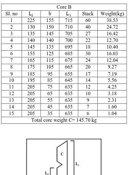
Figure 3: Design of B core PART C
Length of lamination (L) is calculated as (2 C/L + W) mm Where C/L, W are in mm similarly
Weight is calculated as = 2 * [(L – W) * W – 1/2 W2] * Core stack * density * 0.97 *10−3 kg Where L, W and core stack are in cm
Length of 1st step = (2 * 460 + 240) = 1160
[image:6.612.181.431.342.684.2]Weight of 1st step = 2 * [(116 – 24) * 24 – (12∗24)2] * 6.248 * 7.65 * 0.97 * 10−3= 191.38 kg
Table 5: Core C cutting
Core B
SI. no L2 b L1 Stack Weight(kg)
1 225 155 715 60 38.53
2 130 150 710 40 24.72
3 135 145 705 27 16.42
4 140 140 700 22 12.70
5 145 135 695 18 10.40
6 155 125 685 30 16.03
7 165 115 675 24 12.04
8 175 105 665 20 9.27
9 185 95 655 17 7.19
10 195 85 645 14 5.56
11 205 75 635 12 4.25
12 205 65 635 10 3.18
13 205 55 635 9 2.31
14 205 45 635 7 1.60
15 205 35 635 6 1.04
Total core weight C= 145.70 kg
C
L1
L2
ISSN 2250-3153 Total weight of core,
Weight of Part A = 139.18 kg Weight of Part B = 60.04 kg Weight of Part C = 145.70 kg Total weight of core = 344.92 kg
[image:7.612.53.516.164.382.2]So, designed of 250 kVA step down transformers is strongly considering all losses as core and copper losses
Table 6: All losses are considered for design of transformer
Design validation sheet
kVA 250 Voltage 11/.415kV + 2.5% to - 7.5% in step of 2.5% Taping
SI. no Description Units Guaranteed Designed
1 No load loss W 275 273.74
2 No load current A 1% OF FL -
3 Load loss W 2650 2648
4 I2R loss W - 2443
5 Stray loss W - 205
6 Impedance % 4 4.08
7 Reactance % - 3.86
8 HV resistance @ 75°C Ω - 12.95
9 LV resistance @ 75°C Ω - 0.004373
10 Temp rise oil °C 60 -
11 Temp rise wedge °C 65 -
12 LV per coil weight Kg’s - 23.0
13 HV per coil weight Kg’s - 7.36
14 Total job weight Kg’s - 1034
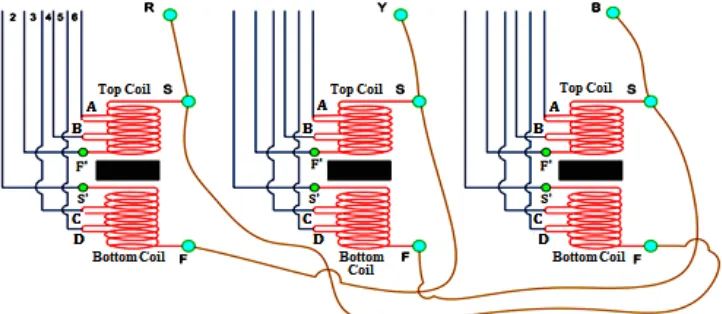
VI. TAP CHANGING PROCESS OF THE PROPOSED TRANSFORMER
[image:7.612.129.490.479.636.2]Tap changing process is the process of selecting or cutting out a certain number of turns on the transformer winding thus obtaining a variable turns ratio. This is done in order to maintain the output voltage within desirable limits because the equipment works satisfactory in the power system [3]. According to the diagram, used 2.5 % tapping for the off load tap changing transformer for this reason output voltage might be five different values and thus from tapping one to tapping five voltage level increase respectively up to a certain position.
Figure 5: Off load tapping connection on 250 kVA transformer Tapping calculation given below:
For 250 kVA transformer used 2.5% tapping High tension coil number of turns = 1524
So the tapping turns will be for 2.5% =1524 * (2.5 / 100) = 38 turns
So, within this 1600 turns the top coil have 800 turns and the bottom coil have 800 turns. The top coil tapping is given at the end of the turns and the three tapping connections for the top coil are given below:
Total Number of turns 800 Start of HT coil (S) = 0 turn Finish of top coil (F’) = 800 turns Tapping point B = 800 – 38 = 762 turns Tapping point A = 762 – 38 = 724 turns
The bottom coil tapping are given at the beginning of the turns and the three tapping connections for the bottom coil are given below: Start of Bottom Coil (S’) = 800 turns
Finish of LT coil (F) = 0 turn
Tapping point C = 800 – 38 = 762 turns Tapping point D = 762 – 38 = 724 turns
VII. PAYBACK ANALYSIS OF THE PROPOSED TRANSFORMER
The payback period is the length of time required to recuperate the preliminary cash expenditure on the project. The proposed transformer has a proven and reliable design which ensures an economical life of the transformer for more than 20 years. The energy efficiency transformer reduces the electricity bill by reducing the total losses as shown in the following example:
Sl no Payback analysis 250 kVA
1 Losses are considered for full load application (utilization factor) 1
2 Electricity charges considered per kWH (cost of Tk./unit) 4.5
3 Rating considered 250 kVA
4 No. of hours in a year (24 * 365) 8760
A Proposed designed energy efficient transformer
No load loss + Full load loss (0.360+2.82) kW
Total load loss (kW) 3.18 kW
B Normal designed ordinary transformer
No load loss + load loss (0.56 + 5.4) kW
Total load losses (kW) 5.96 kW
A1 Electricity bill per year due to losses for proposed transformer
Utilization (1) * price per unit (4.5) * total no of hrs (8760) * loss (22.6) 1, 25, 356 bdt
B1 Electrical bill per year due to losses (bdt)
Utilization (1) * price per unit (4.5) * total no of hrs (8760) * loss (35.6) 2, 34, 943.20 bdt
X Yearly saving due to energy efficient transformer (B1 - A1) 1, 09, 587.00 bdt
P1 Approximate price of 250 kVA transformer 4, 00, 000.00 bdt
P2 Price of 250 kVA ordinary transformer 3, 30, 000.00 bdt
P1-P2 Price difference for energy efficient design 70, 000.00 bdt
PB Payback period in year, PB = P1−P2
X 0.64 year
P’B Payback period in month = PB * 12 7.6 month
VIII. RESULT
ISSN 2250-3153
XI. CONCLUSION
In this paper agitated in regard to design hermetically sealed shell type oil immersed distribution transformers with minimum evaluated cost according to the IEC standards. Here very calculatedly describe about the transformer design with proper equations as well as the consequently core and copper design then internal total connection of the transformer. Distribution transformer model and design constraints are implemented as a user-friendly an objective function for total evaluated cost is optimized subjected to ten constraints according to IEC 60076 in addition to geometrical constraints. A design example on a 250kVA transformer is presented for illustration.
REFERENCES
[1] Colonel Wm. T. McLyman “Transformer and Inductor Design Handbook” 4th Edition Published 26 April 2011
[2] ByS.V. Kulkarni, S.A. Khapard “Transformer Engineering Design and Practice”1st Edition First Published 24 May 2004 eBook Published 24 May 2004 Pub. location Boca Raton
[3] MS Calovic “Modeling and Analysis of Under-Load Tap-Changing Transformer Control Systems” IEEE Transactions on Power Apparatus and Systems ( Volume: PAS-103, Issue: 7, July 1984 )
[4] William H. Kersting “Distribution System Modeling and Analysis” 2nd Edition First Published 15 November 2006 eBook Published 15 November 2006 Pub. location Boca Raton
[5] C L Wadhwa “Electrical Power Systems” (2009), New Academic Science Ltd AUTHORS
First Author – Sairatun Nesa Soheli, Senior Lecturer, IUBAT–International University of Business Agriculture and Technology, [email protected]
Second Author – Md Saidul Hasan, Instructor, Northern Science and Technology, [email protected]
Third Author – Md Refat Uddin, IUBAT–International University of Business Agriculture and Technology, [email protected]