ISSN 2250-3153
DESIGN OPTIMISATION OF A COMPOSITE
CYLINDRICAL PRESSURE VESSEL USING FEA
K. Sahitya Raju*, Dr. S. Srinivas Rao **.
*
Department of Mechanical Engg. M. V. G. R. College of Engineering
**
Department of Mechanical Engg. M. V. G. R. College of Engineering
Abstract- Interest in studying of the shell arises from the fifties of twentieth century. The assemblies, containing thin shells, find wide use in the modern engineering, especially in ships, aircraft and spacecraft industry. The shell vibrations and buckling modes are analyzed by means of numerical methods, to clarify qualitatively the critical loads and different buckling modes.In today’s aerospace and aircraft industries, structural efficiency is the main concern. Due to their high specific strength and light weight, fiber reinforced composites find a wide range of applications. Light weight compression load carrying structures form part of all aircraft, and space vehicle fuel tanks, air cylinders are some of the many applications. In the present work, design analysis of fiber reinforced multi layered composite shell, with optimum fiber orientations; minimum mass under strength constraints for a cylinder under axial loading for static and buckling analysis on the pressure vessel has been studied. The modeling is carried out in Catia V5 R20 and the analysis is carried out in Ansys 15.0 solver.
Index Terms- lightweight compression, reinforced multi-layered, thin shells.
I. INTRODUCTION
Pressure vessels are important because many liquids and gases must be stored under high pressure. Special emphasis is placed upon the strength of the vessel to prevent explosions as a result of rupture. Codes for the safety of such vessels have been developed that specify the design of the container for specified conditions. Most pressure vessels are required to carry only low pressures and thus are constructed of tubes and sheets rolled to form cylinders. Some pressure vessels must carry high pressures, however, and the thickness of the vessel walls must increase in order to provide adequate strength.
Cylindrical shells (see Fig.1) such as thin-walled laminated composite unstiffened vessels like deep submarine exploration housings and autonomous underwater vehicles are subjected to any combination of in plane, Out of plane and shear loads due to the high external hydrostatic pressure during their application. Due to the geometry of these structures, buckling is one of the most important failure criteria. Buckling failure mode of a stiffened cylindrical shell can further be subdivided into global buckling, local skin buckling and stiffener crippling. Global buckling is collapse of the whole structure, i.e. collapse of the stiffeners and the shell as one unit. Local skin buckling and the stiffeners crippling on the other hand are localized failure modes involving local failure of only the skin in the first case and the stiffeners in the second case.
Fig.1. Cylindrical Shells
II. PROBLEMIDENTIFICATION
ISSN 2250-3153
to design and predict the behaviour of fiber reinforced composite pressure vessels. The classical lamination theory and generalized plane strain model is used in the formulation of the elasticity problem.
Internal pressure axial force and body force due to rotation in addition to temperature and moisture variation throughout the body are considered. Some 3D failure theories are applied to obtain the optimum values for the winding angle, burst pressure, maximum axial force and the maximum angular speed of the pressure vessel
In the present work, design analysis of fiber reinforced multi layered composite shell, with optimum fiber orientations; minimum mass under strength constraints for a cylinder with or without stiffeners under axial loading for static and buckling analysis on the pressure vessel has been studied.
III.
MODELINGOF CYLINDRICAL PRESSURE VESSELThe modeling of the Cylindrical Pressure Vessel is done in Catia V5 R20.
Introduction to Catia V5 R20:
CATIA-V5 is the industry’s de facto standard 3D mechanical design suit. It is the world’s leading CAD/CAM /CAE software, gives a broad range of integrated solutions to cover all aspects of product design and manufacturing. Much of its success can be attributed to its technology which spurs its customer’s to more quickly and consistently innovate a new robust, parametric, feature based model. Because that CATIA-V5 is unmatched in this field, in all processes, in all countries, in all kind of companies along the supply chains.
Catia-v5 is also the perfect solution for the manufacturing enterprise, with associative applications, robust responsiveness and web connectivity that make it the ideal flexible engineering solution to accelerate innovations. Catia-v5 provides easy to use solution tailored to the needs of small medium sized enterprises as well as large industrial corporations in all industries, consumer goods, fabrications and assembly. Electrical and electronics goods, automotive, aerospace, shipbuilding and plant design. It is user friendly solid and surface modeling can be done easily.
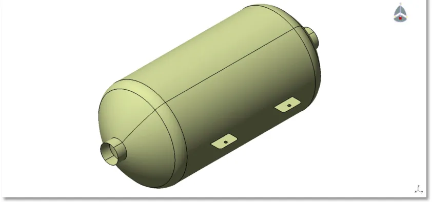
[image:2.612.95.516.422.619.2]The model is as shown in the figure 2 as shown below:
Fig 2. Cylindrical pressure vessel Model
ISSN 2250-3153
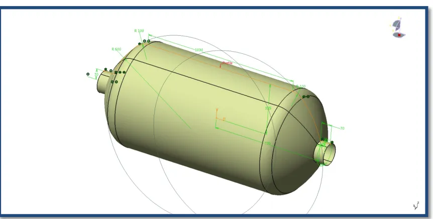
Fig. 3 Drawing Specifications for the Cylindrical Pressure Vessel.
Fig. 4 Drawing Specifications for the Cylindrical pressure vessel.
IV. ANALYSISOFCYLINDRICALPRESSUREVESSEL
The analysis of the cylindrical pressure vessel is done in Ansys 15.0 and the analysis reports are as shown below.
[image:3.612.92.523.279.497.2]ISSN 2250-3153
[image:4.612.85.544.56.228.2]Fig. 5 Geometry of the cylindrical pressure vessel
Fig. 6 Mesh of the cylindrical pressure vessel
The analysis is carried out for the Steel material and the composite material for the cylindrical pressure vessel.
Analysis of Steel cylindrical pressure vessel:
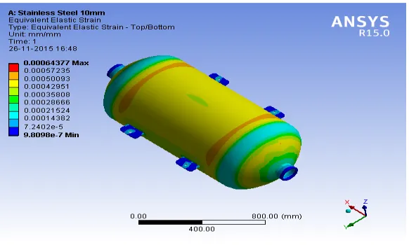
The Boundary Conditions are given as the pressure of 3MPa and fixed at the stiffeners of the pressure vessel. The deformation and Equivalent Stress reports for the steel cylindrical pressure vessels are are as shown in the Fig. 5 and Fig. 6 respectively.
[image:4.612.75.560.316.467.2] [image:4.612.307.557.317.464.2]Fig. 7 Deformation of the Steel pressure vessel
Fig.8 Equivalent Stress of the Steel pressure vessel [image:4.612.180.471.497.672.2]
ISSN 2250-3153
The deformation and Equivalent Stress reports for the composite cylindrical pressure vessels are are as shown in the Fig. 10 to Fig. 12 respectively.
[image:5.612.81.569.97.248.2] [image:5.612.79.319.99.250.2][image:5.612.187.459.293.469.2]
Fig. 10 Deformation of the Composite pressure vessel-250 Fig.11 Equivalent Stress of Composite pressure vessel-250
Fig.12 Equivalent Stress of the composite pressure vessel-250
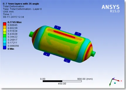
Also the analysis is carried out for the leaf spring which consists of composite material 8 layers, 9 layers and 10layers. The deformation of and the Equivalent Stress reports for the composite cylindrical pressure vessel are shown in the Fig. 13 to Fig. 18 respectively.
[image:5.612.75.290.556.710.2] [image:5.612.345.561.559.710.2]
ISSN 2250-3153
Fig.15 Equivalent Stress of the hybrid cylindrical pressure vessel-Layer 2 for 350
Fig.16 Deformation of the composite pressure vessel-450 Fig.17 Equivalent Stress of the composite pressure vessel-450
Fig.18 Equivalent Stress of the composite pressure vessel-Layer 2 for 450
ISSN 2250-3153
V. RESULTS AND DISCUSSION
The analysis of Steel Cylindrical pressure vessel with the composite cylindrical pressure vessel is done. In addition we would like to change the orientation of composite cylindrical pressure vessel in such a way that the thickness is 1mm with variants of 7 layers, 8 layers, 9 layers and 10layers of composite allowed with an angle of 250, 350, 450,550,650,750 and 900.
[image:7.612.33.578.167.439.2]The results for the composite pressure vessel of 1mm with 7 layers and different angles of orientation are as shown below:
Table 1: Composite pressure vessel of 1mm with 7 layers and different angles of orientation
Total Deformation
(mm)
Equivalent Stress-Layer 1 (Mpa)
Equivalent Stress-Layer 2 (Mpa)
7 1mm layers with 25 degree angle orientation 0.8211 310.07 36.236
7 1mm layers with 35 degree angle orientation 0.7745 298.59 32.213
7 1mm layers with 45 degree angle orientation 0.7873 300.56 29.372
7 1mm layers with 55 degree angle orientation 0.8601 316.7 33.56
7 1mm layers with 65 degree angle orientation 1.0889 326.02 37.128
7 1mm layers with 75 degree angle orientation 1.2292 328.3 39.001
7 1mm layers with 90 degree angle orientation 1.2948 327.2 39.819
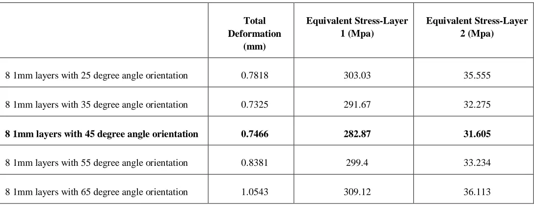
The results for the composite pressure vessel of 1mm with 8 layers and different angles of orientation are as shown below:
Table 2: Composite pressure vessel of 1mm with 8 layers and different angles of orientation
Total Deformation
(mm)
Equivalent Stress-Layer 1 (Mpa)
Equivalent Stress-Layer 2 (Mpa)
8 1mm layers with 25 degree angle orientation 0.7818 303.03 35.555
8 1mm layers with 35 degree angle orientation 0.7325 291.67 32.275
8 1mm layers with 45 degree angle orientation 0.7466 282.87 31.605
8 1mm layers with 55 degree angle orientation 0.8381 299.4 33.234
[image:7.612.38.582.514.723.2]ISSN 2250-3153
8 1mm layers with 75 degree angle orientation 1.1853 311.39 37.568
8 1mm layers with 90 degree angle orientation 1.246 314.98 38.219
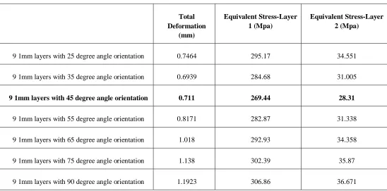
[image:8.612.33.581.189.460.2]The results for the composite pressure vessel of 1mm with 9 layers and different angles of orientation are as shown below:
Table 3: Composite pressure vessel of 1mm with 9 layers and different angles of orientation
Total Deformation
(mm)
Equivalent Stress-Layer 1 (Mpa)
Equivalent Stress-Layer 2 (Mpa)
9 1mm layers with 25 degree angle orientation 0.7464 295.17 34.551
9 1mm layers with 35 degree angle orientation 0.6939 284.68 31.005
9 1mm layers with 45 degree angle orientation 0.711 269.44 28.31
9 1mm layers with 55 degree angle orientation 0.8171 282.87 31.338
9 1mm layers with 65 degree angle orientation 1.018 292.93 34.358
9 1mm layers with 75 degree angle orientation 1.138 302.39 35.87
9 1mm layers with 90 degree angle orientation 1.1923 306.86 36.671
[image:8.612.37.583.532.716.2]The results for the composite pressure vessel of 1mm with 10 layers and different angles of orientation are as shown below:
Table 4: Composite pressure vessel of 1mm with 10 layers and different angles of orientation
Total Deformation
(mm)
Equivalent Stress-Layer 1 (Mpa)
Equivalent Stress-Layer 2 (Mpa)
10 1mm layers with 25 degree angle orientation 0.7102 288.34 33.753
10 1mm layers with 35 degree angle orientation 0.655 277.54 30.724
10 1mm layers with 45degree angle orientation 0.673 261.66 30.052
ISSN 2250-3153
10 1mm layers with 65 degree angle orientation 0.9778 284.21 33.584
10 1mm layers with 75 degree angle orientation 1.0888 294.59 34.954
10 1mm layers with 90 degree angle orientation 1.1396 299.91 35.269
VI. CONCLUSION
This project work involves the comparison of conventional steel and Composite material cylindrical pressure vessel under static loading conditions the model is preferred of in Catia V5 R20 and then analysis is perform through ANSYS 15.0 from the result obtained it will be concluded that the development of a composite cylindrical pressure vessel having constant cross sectional area, where the stress level at any station in the Composite pressure vessel is considered drop and rise due to the orientation of composite, has proved to be very effective. Taking weight into consideration, we can conclude that 7layers gives lesser weight. But, taking stress and weight into consideration, 10layers is giving the desired result. The results are found to be effective for the composite lamia for 450 orientations. The deformation is tending to reduce for the 10layers composite orientation so as the Equivalent Stress. The Lamina stacking sequence is appropriate which is free from extension – bending, coupling which reduces the effective stiffness of the lamina, since the laminates are symmetric. Appropriate number of plies needed in each orientation and thickness of the shell is safe from static and buckling analysis is concerned. The comparison plots obtain desired results for stresses and deformations with lamina orientations for the chosen composite materials.
REFERENCES
[1] Rao Yarrapragada K.S.S, R.Krishna Mohan, B.Vijay Kiran, “Composite Pressure Vessels”, International Journal of Research in Engineering and Technology, Volume: 01 Issue: 04 | Dec-2012.
[2]Mouritz. A.P., Gellert. E., Burchill. P and Challis. K., “ Review of advance composite structures for naval ship and submarines”, Composite structures, vol-53,pp 129-139 (1996).
[3] Alexis A. Krikanov., “ Composite pressure vessels with higher stiffness” 1999 Elsevier science Ltd. Composite structures, vol-48, pp 119-127 (2000).
[4] S. Adali, E.B. Summers & V.E. Verijenko., “Optimization of Laminated Cylindrical pressure vessels under strength criterion”, Composite structures, vol-25, pp 305-312 (1993), University of national Durban 4001, South Africa.
[5] Tae-Uk Kim., Hvo-Chol Sin., “Optimal design of composite laminated plates with the discreteness in ply angles and uncertain in material properties considered”, Computers and Structures 79, pp 2501-2509, (2001).
[6] Levend Parnas., Nuran Katirei.,“Design of Fiber-Reinforced Composite pressure vessels under various loading conditions”, Composite structures 58, pp 83-95 (2002).
[7] Graham J., “preliminary Analysis Techniques for Ring and Stringer Stiffened Cylindrical Shells,” NASA report TM-108399, March 1993.
[8] Phillips J.L., Gurdal Z., “Structural Analysis and Optimum Design of Geodesically Stiffened Composite Panels,” NASA Report CCMS-90-05, July 1990. [9] Jaunky N., Knight N.F., Ambur D.R., “ Optimum Design and General Stiffened Composite Circular Cylinders for Global Buckling With Strength Constraints,” Journal of Composite Structures, March 1998.
[10]Park, O., Haftka, R.T., Sankar, V.V. and Nagendra, S., “Analytical and Experimental Study of a blade stiffened panel in Axial Compression,” proceedings of the 39th AIAA/ ASME/ ASCE/ AHS/ ASC Structures, Structural Dynamics and Materials Conference, Long Beach CA. April 20-23 1998. AIAA- 98-1993. [11] S.B. Filippov , D.N. Ivanov , N.V. Naumova., “ Free Vibrations and Buckling of a Thin Cylindrical shell of Variable Thickness with Curvilinear Edge, ” TECHNISCHE MECHANIK, Band 25, Heft 1, (2005), 1-8 Manuskripteingang: 15. January 2004.
[12] Hyer M.W., Riddick J.C., “ Effect of Imperfections of Buckling and Post buckling Response of Segmented Circular Composite Cylinders,” Proceedings of the 6th Annual Technical Conference of the American Society for Composites, Virginia 2001.
[13] Knight N.F., Strance J.H., “Development in Cylindrical Shell Stability Analysis,” NASA report, 1997.
[14] Mc Donnell Douglas astronautics company, “Isogrid design hand book”, for NASA Marshal Space Flight Center contract AUTHORS
First Author – K. Sahitya Raju, M. Tech, Machine Design, Department of Mechanical Engg, M.V.G.R.College of Engineering.
Second Author – Dr. S. Srinivas Rao, Associate Professor, Department of Mechanical Engg. M. V. G. R. College of Engineering.