Dynamic Performance Analysis of IG based Wind Farm
with STATCOM and SVC in MATLAB / SIMULINK
Amit Garg
Assistant Engineer, Uttar Haryana Bijli Vitran
Nigam, Haryana, India.
Ravindra Pratap Singh
Director,
BDES Group of Institutions, JB Knowledge Park, Faridabad,
Haryana, India.
ABSTRACT
Voltage Stability is a key factor for the stable operation of grid connected wind farm during fault through and grid disturbances. This paper investigates the implementation and comparison of FACTS devices like STATCOM and SVC for the voltage stability issue for IG-based wind farm connected to a grid and load. The steady state behaviour of an interconnected IG based wind farm with STATCOM and SVC is studied and compared for performance evaluation of the two FACTs devices. The power system model is simulated in MATLAB / SIMULINK and the results show that the STATCOM is better than SVC for the stable operation of wind turbine generator system to remain in service during grid faults.
Keywords
Dynamic Performance, Induction Generator, FACTs, Power System Stability, Matlab/Simulink, Transient Stability,Wind Power Plant
1.
INTRODUCTION
In the last few years, there is a strong trend towards decentralized production and supply, leading to a solution where a growing number of small and medium size producers are connected to energy networks[17]. But at the same time, the power quality of the generation must be ensured and this means that the electrical parameters of the distribution network have to be maintained within their upper and lower limits. Therefore, new problems related to the management and operation of energy transfer and distribution and efficient distribution of renewable energy in the grids are actually arising[18]. Hence, it is reasonable to think that dispersed generation should start to take part in the control of electric variables, and in particular, in reactive power control which is directly related to the voltage level control of distribution networks [16].There is an increasing concern over the environmental impact and sustainability of traditional fossil-fuelled power plants. Wind energy is one of the most important and promising renewable energy resources in the world, leading to a growing penetration of the wind energy in electrical system[19]. As a consequence, the number of small size wind farms used as DG sources located within the distribution system is rapidly increasing in recent years[1]. Installing wind farm in the distribution system can defer the investments for the distribution system expansion, but at the same time, the power quality of the distribution network has to be ensured. Hence, wind farms are more and more required to take part in the control of electric variables and in particular in reactive power control [17]. The variable-speed wind turbine equipped with Induction generator (IG) is widely used generator in wind farms. The Induction generator is able to
obtain the maximum active power from wind speed and the generated reactive power can be controlled in an independent way[20]. Utilizing IG reactive power control capability, wind farm made up with IG can be used as the continuous reactive power source to support system voltage control without causing any interference in their active power generation process[2]. Wind farm reactive power control can reduce power losses and improve the voltage profile at the user terminal by providing reactive power compensation in distribution systems. The benefits of compensation depend greatly on the IG wind turbine reactive power output capability. The idea is to find the optimal wind farm reactive power output to minimize losses and improve voltage profiles in the distribution system[18].A wind farm comprising IG wind turbines is proposed as a continuous reactive power source to support system voltage control due to reactive power control capability of IG[5]. Wind farms are located in geographical areas which have continuous, steady, favourable wind in the speed range between 6m/s to 30 m/s. Annual average wind speed of 10m/s is considered to be very suitable, A wind farm has several wind turbine generator units[6]. A typical wind farm may have 5 to 50 wind turbine generator units of small or medium size. Large wind turbine generator units are generally built as single units (without wind-farm) [20].
The electrical generators with the wind turbine units are of two types[19]
1. 50 Hz a.c. synchronous generators with constant speed connected to the grid.
2. Variable frequency a.c induction generator with variable speed.
Following options are available for wind electric energy conversion plants.
1. Stand alone generators with battery storage support.
2. Wind energy conversion plants in parallel with the electrical grid as energy displacement plants. Battery storage is not necessary in these energy conversion plants.
3. Wind-diesel hybrid for remote stand alone systems.
2. OUTLINE OF FACTS DEVICES
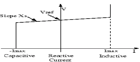
Fig 1: The V-I Characteristics of SVC
2.2
Transient Stability with SVC
The SVC can be operated in two different modes[22]:
In voltage regulation mode.
In var control mode (the SVC susceptance is kept constant).
When the SVC is operated in voltage regulation mode, it implements the V-I characteristic shown in Fig. 1.
As long as the SVC susceptance B stays within the maximum and minimum susceptance values imposed by the total reactive power of capacitor banks (Bcmax) and reactor banks (Blmax), the voltage is regulated at the reference voltage Vref[26]. However a voltage droop is normally used usually between 1% and 4% at maximum reactive power output).
The V-I characteristic is described by the following three equations
V=Vref + Xs.I SVC is in regulation range (-Bmax< B <BLmax) (1)
V= -I / Bcmax SVC is fullycapacitive (B=Bcmax) (2)
V=I / Blmax SVC is fully inductive (B=BLmax) (3)
Where,
V = Positive sequence voltage (p.u.)
I = Reactive current (p.u./Pbase) (I > 0 indicates an inductive current)
Xs = Slope or droop reactance (p.u./Pbase)
BCmax = Maximum capacitive susceptance (p.u./Pbase) with all TSCs in service, no TSR or TCR
BLmax = Maximum inductive susceptance (p.u./Pbase) with all
TSRs in service or TCRs at full conduction, no TSC
Pbase = Three-phase base power
2.3
Static Synchronous Compensator
(STATCOM)
[image:2.595.315.542.113.213.2]
Fig 2: V-I Characteristics of STATCOM
As long as the reactive current stays within the minimum and minimum current values (-Imax, Imax) imposed by the converter rating, the voltage is regulated at the reference voltage Vref. However, a voltage droop is normally used (usually between 1% and 4% at maximum reactive power output), and the V-I characteristic has the slope indicated in the figure. In the voltage regulation mode, the V-I characteristic is described by the following equation:
V=Vref + Xs I (4) Where
V : Positive Sequence Voltage (pu)
I : Reactive Current (I>0 indicates an Inductive Current)
Xs: Slope or Droop Reactance
3.
SIMULATION
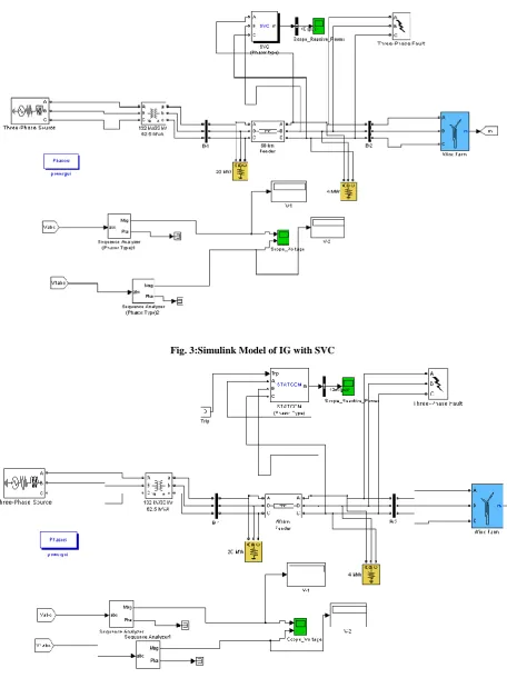
Fig. 3:Simulink Model of IG with SVC
Fig.4: Simulink Model of IG with STATCOM
6. SIMULATION RESULTS AND DISCUSSIONS
[image:4.595.57.541.456.688.2]Fig.5 : Voltages at 33 kV Bus – 1 and Bus – 2 during SVC
Fig. 5 shows the voltages at 33 kV Bus – 1 and Bus – 2 during the operation of SVC located at the point of wind farm
connection.
Fig.6: Reactive Power of SVC
Time (s) V1 (p.u.) V2 (p.u.) Reactive Power by SVC (MVAR)
1 .9265 .9663 -1.501
2 .9379 .9752 -.8471
3 .9378 .9737 -.8373
4 .9373 .9732 -.8702
5 .9377 .9728 -.8815
6 .9213 .9769 -.7522
7 .9213 .9769 -.7522
8 .9213 .9769 -.7522
9 .9213 .9769 -.7522
10 .9213 .9769 -.7522
10.125 .8491 1.0 -3.861
10.150 .8491 1.0 -3.861
10.199 .8491 1.0 -3.861
10.2 .9196 .9727 -.6692
10.3 .9213 .9769 -.7522
10.5 .9213 .9769 -.7522
11 .9213 .9769 -.7522
12 .9213 .9769 -.7522
13 .9213 .9769 -.7522
14 .9213 .9769 -.7522
15 .9213 .9769 -.7522
16 .9213 .9769 -.7522
17 .9213 .9769 -.7522
18 .9213 .9769 -.7522
19 .9213 .9768 -.7524
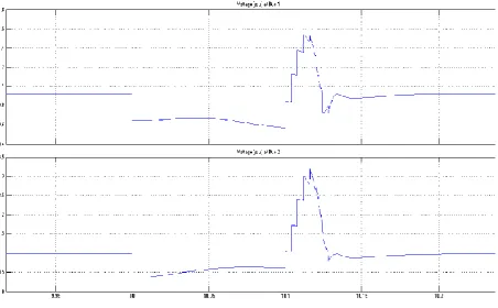
Fig.7: Voltages at 33 kV Bus – 1 and Bus – 2 during STATCOM
Fig. 7 and Fig. 8 shows the voltages at 33 kV Bus – 1 and Bus – 2 during the operation of STATCOM located at the
point of wind farm connection.
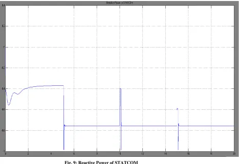
Fig. 9: Reactive Power of STATCOM
Fig.9 and Fig.10 shows the Reactive Power supplied by STATCOM to the network.
[image:7.595.65.533.70.391.2]
7. CONCLUSION
Hence Both the system, IG with STATCOM and other IG with SVC is operated with same load. The system is tested under the voltage regulation mode of STATCOM and SVC to analyze and compare the behavior of both the system on the basis of voltage and reactive power flow . However analyzing the reactive power flow for stabilizing the system voltage then it is quite clear then settling time and reactive power for the
a SVC is proportional to the square of the system voltage (constant susceptance) while the maximum capacitive power generated by a STATCOM decreases linearly with voltage decrease (constant current). This ability to provide more capacitive power during a fault is one important advantage of the STATCOM over the SVC. In addition, the STATCOM will normally exhibits a faster response than the SVC because with the voltage-sourced converter, the STATCOM has no
Time (s) V1 (p.u.) V2 (p.u.) Reactive Power by
STATCOM (MVAR)
1 .6369 .3376 6.909e-010
2 .6369 .3376 6.909e-010
3 .6347 .3324 3.62e-012
4 .6342 .3311 -2.837e-013
5 .6338 .3304 5.364e--013
6 .8927 .9067 -3.431e-009
7 .8927 .9067 -.5.042e-009
8 .8927 .9067 -6.816e-009
9 .8927 .9067 -1.347e-009
10 .8927 .9067 -3.018e-010
10.1 .6361 .365 9.228e-010
10.109 .8927 .9067 1.3e-010
10.112 .8927 .9067 1.3e-010
10.125 .8927 .9067 1.3e-010
10.150 .8927 .9067 1.3e-010
10.199 .8927 .9067 1.3e-010
10.2 .8927 .9067 1.276e-011
10.3 .8927 .9067 -1.154e-008
10.5 .8927 .9067 1.039e-012
11 .8927 .9067 2.792e-008
12 .8927 .9067 7.409e-008
13 .8927 .9067 4.543e-008
14 .8927 .9067 -5.131e-008
15 .8927 .9067 4e-010
16 .8927 .9067 1.644e-009
17 .8927 .9067 2.029e-010
18 .8927 .9067 2.202e-009
19 .8927 .9067 4.351e-009
significant length of time. So in this paper it is successfully demonstrated that how STATCOM has successfully been applied to IG based wind farm connected to grid and load for effectively regulating system voltage.
8. REFERENCES
[1] Sol-Bin Lee, Kyo-Beum Lee, Dong-Choon Lee and Jang-Mok Kim ―An Improved Control Method for a DFIG in a Wind Turbineunder an Unbalanced Grid Voltage Condition‖ Journal of Electrical Engineering & Technology Vol. 5, No. 4, pp. 614~622, 2010
[2] B. Pokharel and Wenzhong Gao, ―Mitigation of disturbances in DFIG-based wind farm connected to weak distribution system using STATCOM,‖ in Proc. IEEE North American Power Symposium, pp. 1-7, 26-28 Sept. 2010.
[3] J. Machowski, J.W. Bialek, J.R. Bumby, Power System Dynamics –Stability and Control, John Wiley & Sons, 2008
[4] B. Sookananta, S. Galloway, G. M. Burt and J. R. McDonald, ―The Placement of FACTS Devices in Modern Electrical Network‖, UPEC,2006
[5] A. Petersson, T. Petru, and T. Thiringer, ―Grid Disturbance Response of Wind Turbines Equipped with Induction Generator and Doubly-Fed Induction Generator‖, in Proceedings of 2003 IEEE PES General Meeting, Toronto, Canada, July 13-17, 2003.
[6] J.G Slootweg, S.W.H. de Haan, H. Polinder, and W.L Kling, ―General Model for Representing Variable Speed Wind Turbines in Power System Dynamics Simulations‖, IEEE Transactions o Power Systems, Vol. 18, No. 1, February 2003.
[7] J. Feltes, Y. Kazachkov, R. Zavadil, ―Modeling Wind Farms for Power System Stability Studies‖, Procedings of 2003 IEEE Power Engineering Society General Meeting, Toronto, Canada, 13-17 July 2003.
[8] S. Smith, R. Todd, M. Barnes, P.J. Tavner, ―Improved energy conversion for doubly-fed wind generators‖, IEEE Transaction on Industry Applications, Vol. 42, No. 6, pp. 1421-1428, November 2006.
[9] P. Ledesma, J. Usaola, and J.L Rodriguez, ―Models of WECS for Power System Dynamic Studies‖, Proceedings of the 33rd Universities‘ Power Engineering Conference (UPEC‘98), Edinburgh, U.K 8-10 September 1998.
[10] D. Beato, J.L Fernandez, R. Iturbe, P. Ledesma, J.M Rodriguez, J. Usaola, and J.R Wilhelmi, ―Transient Stability Studies in Grids with Great Wind Power Penetration: Modelling Issues and Operation Requirements‖, Proceedings of 2003 IEEE Power Engineering Society General Meeting, Toronto, Canada, 13-17 July 2003.
[11] F.W. Koch, I. Erlich, and F. Shewarega, ―Dynamic simulation of large wind farms integrated in a multi machine network‖, Proceedings of 2003 IEEE Power Engineering Society General Meeting, Toronto, Canada, 13-17 July 2003.
[12] M.G. Ioannides, J.A. Tegopoulos, ―Generalized optimization slip power recovery drives‖, IEEE Transactions on Energy Conversion, Vol. 5, No. 1, pp. 91-97, March 1990.
[13] I. Cadirci, M. Ermis, ―Double-output induction
synchronous speeds: Steady-state performance optimization and wind-energy recovery‖, IEEE Proceedings-Electric Power Applications, Vol. 139, No. 5, pp. 429-442, September 1992.
[14] M.S. Vicatos, J.A. Tegopoulos, ―Steady state analysis of a doubly-fed induction generator under synchronous operation‖, IEEE Transaction on Energy Conversion, Vol. 4, No. 3, pp. 495-501, September 1989.
[15] P.C. Krause, O. Wasynczuk, M.S. Hildebrandt, ―Reference frame analysis of a slip energy recovery system‖, IEEE Transactions on Energy Conversion, Vol. 3, No. 2, pp. 404-408, Jume 1988.
[16] D. Kastha, T.B. Isha, ―Steady-state performance of a novel stand-alone variable speed constant frequency generation system‖, 29th Annual IEEE Power Electronics Specialists Conference, Vol. 2, pp. 2115-2121, Fukuoka, Japan, 17-22 May 1998.
[17] Global Wind Energy Council (GWEC) “US and China in Race tothe Top of Global Wind Industry” News dated 02/02/2009, Annx. –Tables and Graphs (online) available www.gwec.net.
[18] “Ministry of New and Renewable Energy (MNRE)”, Govt. of India, official website: www.mnes.nic.in
[19] Rolf Grünbaum, ”Voltage And Power Quality Control In Wind Power Applications Means of Dynamic Compensation” ABB Power Systems AB, AC Power Division Vasteras, Sweden.
[20] Sidhartha Panda and N.P.Padhy , “Power Electronics Based FACTS Controller for Stability Improvement of a Wind Energy Embedded Distribution System”, International Journal of Electronics,Circuits and Systems Volume 1 Number1.
[21] S. Kahrobaee, S. Afshania, V. Salehipoor (University of Tehran), “Reasonable Reactive Power Control and Voltage Compensation for Wind Farms Using FACTS Devices”, Nordic Wind Power Conference 22 – 23 May – 2006, ESPOO, Finland.
[22] Hydro-Quebec, “SimPowerSystemsTM 5 User Guide” October 2008, (online) available: www.mathworks.com. [24] Ahmed Maria, Mauro Facca & John Diaz De Leon
“IESO Philosophy On Reactive Power Compensation”
North AmericanWINDPOWER ® June 2007 issue.
[26] Nang Sabai, and Thida Win (2008) “Voltage control and dynamic performance of power transmission system using SVC” World Academy of Science, Engineering and Technology 42 Pp. 425-429
[27] P.Kundur, “Power system stability and control”, Mc Graw-Hill, 1994
[28] D. Murali (October 2010),”Comparison of FACTS devices for power system stability enhancement” International Journal of Computer Applications (0975 – 8887) Volume 8– No.4, Pp. 30-35 [29] H. Yazdanpanahi ,”Application of FACTS devices in transmission expansion to overcome the problems related to delays”.
[30] A.E. Hammad, “Analysis of power system stability enhancement by static var compensator”, IEEE PWRS, vol 1, no 4, pp. 222-227.