Tracking Line Segment without Knowledge of Camera
Motion
S. Ait Kaci Azzou
LRSD laboratory, computer science department,
University Ferhat Abbas Setif, Algeria,
M.C Baba Hnini
Computer Science Department University of Biskra, Algeria
ABSTRACT
In this paper, a new method for line segments matching for indoor reconstruction will be presented. The problem of line segment tracker is addressed, which does not require any knowledge about the motion of the camera nor the structure of the observed scene. The slopes of lines segment as feature to track are used in order to deal with the instability of the endpoint extraction. The proposed method relies solely on the geometry layout of the slope of the segment and not on photometric or color profiles and does not need any knowledge about the parameters of the camera or its rotation. The obtained results showed the feasibility of the method.
General Terms
Computer vision
Keywords
Tracking, line segment, Matching.
1.
INTRODUCTION
The development of algorithms for tracking objects in image sequences is a major problem for many applications related to computer vision, robotics, etc.. A reliable extraction and tracking of spatio-temporal visual information is indeed a key to the success or failure of such applications.
Two main methods for tracking exist: those based on the contour and those based on the texture of the object. The first approach is essential to track the primitives in the image space or 3D geometric primitives like (points, lines, circles ...). The contour of the object, the projection of the contours of a 3D object, etc. The latter uses a correlation criterion related to the information given by the grayscale pattern of the object or other information presented in this pattern (color...).
Tracking method based edge depends on the strong spatial gradients defining the edge of the object or some geometric primitives present in a pattern (points, lines, distances ...). With regard to tracking in the space of the image (2D tracking), this approach describes the object to follow using geometric primitives as special points [1,2], angles, contours [3,4], line segments [5, 6] or ellipses [7], etc..
However, just look around us to deduce that the line segment is a very expressive primitive in our environment. Line
which many applications can be built (recognition of structured objects [8], or 3D reconstruction structured scenes in robotics [9, 10]). Segments were indeed several interesting properties: they are naturally perfectly straight lines in the scene; they can be used to estimate various geometric transformations, and are invariant under change of perspective. But this property is only exploitable if the segments extraction algorithms are robust and stable: classical methods are fragile, they are very sensitive to image noise, lighting conditions and change views.
A common way to obtain line segments is to link gradient maximum points [11] in order to assume a contour and apply one of the methods summarized in [12,13,14].
The tracking methods of the segment, developed, are based either on the Kalman filtering [15], where the assumption of "short baselines" is issued, either by using the epipolar line bundles to constrain to constrain good matches [16]. This method is fast and accurate but requires knowledge of the epipolar geometry thus requires camera calibration which makes it unsuitable for camera calibration.
In [17], a segment matching method with an application to wide baseline stereo is presented. Here, feature points (SIFT, HOG, ...) are extracted and used as anchor points. The actual segments pairing are performed by first, grouping putative matches using their color profiles. Then, anchor-point/segment sideness consistency is exploited to sort out the matches. Obviously, if no or few point features were detected and paired, the segment matching will rely solely on color profiles which are known to be unstable.
The proposed approach in this paper, uses line segments rather than points as landmarks, since there are some advantages in using line segments. Images of artificial environments with little texture contain many line segments, whereas few point features can be localized in such a scene. Moreover, line segment detection is more reliable than point detection. Line segment matching is also more robust than point matching with respect to partial occlusion and viewpoint changes.
slope of the line segment because the slopes are more robust to noise than the endpoint of line segments.
One of the highlights, of the method is that using uniquely the mathematical relation between the slopes, on image sequences. The method does not require any knowledge of the calibration of the camera or its motion..
2.
POSITION OF THE PROBLEM
In this work, horizontal rotational camera movement is assumed. The proposed geometrical model is illustrated by figure 1. After each rotation of the camera, a new image is acquired and noted IMi, where i refers to the position number of the camera. In each image some of the line segments or interest points, defining segment, are extracted.
IMi = {Sji, j=1..ni} where ni is the number of segment lines
located in IMi .
B. Geometrical model for the motion of camera rotation
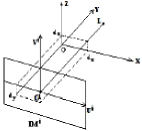
The geometrical model of image formation is defined by (see figure 1).
- Oi is the impact point of the image IMi defined as the intersection of the optical axis with the image plane.
- L is the center of projection of the camera, OiL represent the focal length f.
- (Oi Ui Vi) is the internal reference associated to IMi.
- The theoretical external reference (OXYZ) is defined so as : OX is parallel to OiUi , OY parallel to the optical axis,
The axis of rotation OZ is parallel to OiVi.
- The camera is fixed so that the rotational axis passes through the optical axis. Due to the uncertainty of the mechanics, the OZ axis is close to the impact point whose position is at the distance d between O and L.
- ex, ez define the dimensions of the pixel.
[image:2.595.369.511.90.221.2]None of the defined parameters is known. The aim, is to develop a mathematical relation that allows the computation of the matching parameters without knowledge of the angle of camera rotation. This relation must be independent of the camera model and will use only the coordinates of image points in the different images. The figure 2, shows that when the camera is rotated around the origin O, the projection center L and image plan IMi are also rotated with the same angle.
Fig. 1. Geometrical model for image formation
Fig. 2. The geometrical model of camera rotating
3.
TRACKING METHOD
3.1
Equation of line segment in the initial
image
In the general case, where the camera is rotated by an angle , any point Mi(xi, yi, zi) of the 3D space is projected into
m
i1 ,
where its projective coordinates on the image plane IM1are [18]:
.
x
cos
.
y
d
f
sin
y
.
sin
x
.
cos
-(ex).f.
=
u
1
(1)
.
x
cos
.
y
d
f
sin
z
(ez).f.
=
v1
(2)As the reference (OXYZ) refers to the initial position of the camera, the angle may be considered as equal to zero. Equations 1 and 2 will serve to determine the new coordinates of points after two rotations of the camera.
V
Y
Z
X
U
P
O
L
L
[image:2.595.319.532.262.404.2]Let
S
i be a line segment in the 3D sceneS
i 1be the image of
S
i , on the image IM
1
v= ai,l.u + bi,l , be the equation of
S
i 1
relatively to (O1U1V1)
The coordinates of
m
i 1image on IM1: of any point Mi(xi, yi,
zi) of the segment
S
i are :
ex f d fi
Y
X
m
u
i i 1 , 1 , . .1 (3)
ez f fi
Y
d
Z
m
v
i i 1 , 1 , . .1 (4)
Where ) sin( . ) cos( .
'
x'
-
i 1,
y
X
i i(5)
)
cos(
.
)
sin(
.
'
x'
i 1,
y
Y
i
i(6)
.
z'
i 1 , Z
i (7)As
m
a
m
b
i i i
i
u
v
1
,1.
1
,1, Zi,1 can be written :
f
f
ez
ez
ex
d
Y
b
X
a
z
i i i ii
,1
1 , 1 , 1 , 1 ,
.
.
.
.
(5)3.2
Images of line segments in new images
after camera rotation
After a second rotation of the camera with an angle , the
segment
S
i will be projected on IM
2
as
S
i 2.
Let v= ai,2.u + bi,2 be the equation of
S
i 2
.
Following the same steps described in 3.1 :
f
f
ez
ez
ex
d
Y
b
X
a
z
i i i ii
,2
2 , 2 , 2 , 2 ,
.
.
.
.
(6) (9)Where
)
sin(
.
)
cos(
.
-
x'
i'
2
,
y
X
i i(10)
)
cos(
.
)
sin(
.
'
x'
i 2,
y
Y
i i(11) After little transformation Xi,1 and Yi,1, become
)
sin(
.
)
cos(
.
,2i,2 1
,
X
Y
X
i
i (13))
cos(
.
)
sin(
.
2 , i,2 1,
X
Y
Y
i
i (14)The substitution of Xi,1, and Yi,1 in (5) by their expressions
gives :
C
C
z
i,1ez
.
f
X
i,2.
1
2 (7) Where
.
.
sin(
)
cos(
)
(
)
)
sin(
)
cos(
.
.
1 , 1 , 1 , 2 , 2 1 , 1 , 1f
f
ex
f
ex
d
b
b
a
Y
C
b
a
C
i i i i i i
(8)Dividing equation (7) by (Yi,2 + dy - f), and after
transformations it becomes :
ex
f
b
a
a
i i i.
)
sin(
)
cos(
.
,11 , 2
,
(9)3.3
Computation of the tracking
parameters
For another rotation movement of the camera with angle ,
a new equation is obtained for segments
S
i andS
jwhere v= ai,3.u + bi,3 is the equation of the segmentS
i 3in image IM3.
Equation (9) is also valid for the same segment
S
i after the rotation :ex
f
b
a
a
i i i.
)
sin(
)
cos(
.
,11 , 3 ,
(10)(11) is obtained after dividing equation (9) by (10) :
sin
sin
)
cos(
.
)
cos(
.
1 , 3 , 1 , 2 ,a
a
a
a
i i i i (11) is constant value.
For any segments taken from images 1,2 and 3 if they are
3.4
Principle of Algorithm
The main idea of the method is to compute the values of
() using three triplets of line segments
S
S
S
k j i 1 1 1 , 1 1 , 1 ,
S
iS
jS
k
2 2 2 , 2 2 ,
2 and
S
iS
jS
k
3 3 3 , 3 3 , 3 chosen
respectively from the first, second and the third image.
In the case where the three triplets are matched, solution of equations (11) by means of the slopes of these segment lines gives the same values of ().Let
-
S
S
S
k j i 1 1 1 , 1 1 ,
1 be a selected randomly from the first image
-
S
S
S
k j i 2 2 2 , 2 2 ,
2 and
S
iS
jS
k
3 3 3 , 3 3 ,
3 be two triplets chosen randomly from the second and the third image so as they not match the first triplet.
In this case, the resolution of equations (11), by means of the slopes of these segment lines, gives empirical values of (v).
Let A be the event corresponding to the same values of (v)
computed using other three triplets. As there are n(n-1)(n-2) possible values generated from all possible combinations, the probability of this event is equal to
1
)
2
(
)
1
(
1
)
(
Pr
n
x
n
nx
A
ob
Let B be the event corresponding to another three triplets producing the same values of (v). As the event B is
independent of the event A, the probability that the two events occur one after the other is equal to :
Prob(BA)=Prob(B)xProb(A).
The repeat of this reasoning over all triplets, give the conclusion that the probability that the same values of (v)
will be computed m times decreases towards zero when m increases.
This result constitutes our main idea. It is inspired from the basic principle of the Hough Transform [19], generating all possible values of (v). The values (v) computed from the
maximum number of three triplets constitute the solution of our problem, and these triplets of line segments constitute the result of the matching images.
3.5
Algorithm
Let H be a function computing value of () using a set of three triplets of line segments.
S
iS
jS
kS
iS
jS
kS
iS
jS
k
iH
3
3 3 , 3 3 , 3 2 2 2 , 2 2 , 2 1 1 1 , 1 1 ,
1
,
,
Where
(i) is the ith value of ()
BEGIN
- REPEAT
- Select randomly three triplets
S
iS
jS
k
1 1 1 , 1 1 , 1
S
iS
jS
k
2 2 2 , 2 2 , 2 ,
S
S
S
i j k3 3 3 , 3 3 , 3
- Compute the slopes
-
(
,
)
1
1 1 , 1 1 , 1 1 , 1 1 , 1 , 1 ,
1
a
a
S
S
S
a
i j kfor
i j k-
a
a
a
S
S
S
k j i k j i 2 2 2 , 2 2 , 2 2 , 2 2 , 2 , 2 ,
2
,
)
for
(
-
a
a
a
S
S
S
k j i k j i 3 3 3 , 3 3 , 3 3 , 3 3 , 3 , 3 ,
3
,
)
For
(
- Compute the value of v , by resolving the equation (11)
H
1
v
card
H
1
v
1
card
- Until all triplets are selected
- Select (s) where:
H
s
Max
card
H
i
card
1
1Selected value (s) corresponds to the set of three triplets of line segments which are matched lines.
End.
4.
EXPERIMENTAL RESULTS
4.1
Data of experiments
Two kinds of data are used :
- simulated data serving for the study of the impact of many factors on the uncertainty estimation of rotation angles with the orientation of line segments, the amounts of angles and noise.
- Images of an interior 3D scene acquired by a camera performing pan rotation.
Fig.3.The mechanical support for camera rotation
4.2
Uncertainty in the estimation of
segments slopes
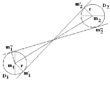
The influences of the noise over the uncertainty of the estimation of the tangencies of segments angles are studied. Instead of adding a Gaussian noise with a mean and standard deviation to image points, displaced the extreme points of line segments into new positions such that the difference between the new and old slopes is maximal. If ml, m2 are the two extremities, their new
positions are m’1, m’2; or m"l, m"2 so as m’1m’2; and
m"lm"2 are the tangencies to the discs Dl(ml,r), D2(m2,r)
(see figure 7).
[image:5.595.92.248.80.186.2]In order to study what are the more robust categories of slopes to noise, the value of 3 pixels for the ray r are used, which allowed the application of algorithm on new slopes that are noisier than in real images.
Fig.7. Noisy line segment
Histograms in figure 8 and 9 illustrate the results obtained for different categories of slopes.
It is clear that the considerable noise decreases the accuracy in the estimation of the slopes.
However, we can conclude that the slopes of long segment are more robust to noise that the short one. And with the same length of line segments, the horizontal one is more robust than the other categories.
Fig.8 Histogram noise/slope
Fig.9. Histogram noise/length
4.3. Tracking line segment for indoor
image
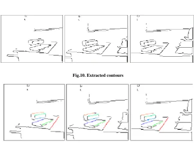
Contour points of the three images illustrated in figure 4,5 and 6 are extracted using the Canny-Deriche detector [20] and approximated by a set straight line segment (see figure 10). The algorithm of section 3.5 is applied to the estimation matching line segments.
In order to increase the accuracy of computed values of (), all combinations of segments are used, for which the absolute slopes appertain to horizontal or oblique segment. If n is the number of matched lines for each one of the three images, the number of values of () is C3n
values.
[image:5.595.83.265.406.547.2]Fig.10. Extracted contours
Fig. 11. Same color indicates the segments in correspondance
The average values of () computed are (0,497237), while the real values are (0,491961).
The result appears very interesting because the estimated value is very near of real one.
Fig 4. Initial image Fig 5. Second image Fig 6. Final image
[image:6.595.101.490.226.511.2]
4.4. Other Examples of experimental results
a) Sequence of 3 real images (puce)
Images are segmented by Canny-Deriche method
The value of () which has the big vote gives the line segments which are in correspondence.
The matching segments are as follow
The segments with same colors are in correspondence.
B) Sequence of 3 real images (chair)
Images are segmented by Canny-Deriche method
The value of Sigma which has the big vote gives the line segments which are in correspondence.
The segments with same colors are in correspondence. The Number on the segment indicate the order of its extraction on image
5.
CONCLUSION
In this paper a novel method is presented to match line segments in an indoor environment.
Our contribution in this work is :
• The proposition of a method which resolves the problem of matching the segment features without any knowledge about camera’s motion or its parameters comparing to others witch necessitate the calibration of the cameras.
• The proposed algorithm is based uniquely on the simple mathematical formulation exiting between the slopes of line segments in successive images where the others suppose the camera motion are known or necessitate a set of initial matching features.
• The method is robust to noise because the slope is more robust than the endpoint of the segment.
• The method is completely intensity-blind as no photometric information was used to achieve the matching.
The tracker algorithm tested on synthetic data generated by computer gives expected results on noisy and not noisy data.
Applied also to real images segmented by Canny-Deriche's method, the proposed algorithm gives suitable results. Furthermore, the experiment shows that the algorithm gives better results for the oblique segments (< = 45 °) and for longer segments with regard to the short ones.
The proposed method depends strongly on the robustness of the algorithm of the extraction of line seegment
6.
REFERENCES
[1] B.D. Lucas and T. Kanade. An iterative image registration technique with an application to stereo vision. In IJCAI’81, pages 674–679, 1981
[2] J. Shi and C. Tomasi. Good features to track. In CVPR’94, pages 593–600, Seattle, Washington, June 1994.
[3] M.-O. Berger. How to track efficiently piecewise curved contours with a view to reconstructing 3D objects. In ICPR’94, pages 32–36, Jerusalem, October 1994. [4] A. Blake and M. Isard. Active Contours. Springer
Verlag, April 1998.
[5] S. Boukir, P. Bouthemy, F. Chaumette, and D. Juvin. A local method for contour matching and its parallel implementation. MVA’98, 10(5/6):321–330, April,1998. [6] G. Hager and K. Toyama. The XVision system: A
general-purpose substrate for portable real-time vision applications. CVIU’98, 69(1):23–37, January 1998. [7] M. Vincze. Robust tracking of ellipses at frame rate.
Pattern Recognition, 34(2):487 – 498, February 2001 [8] P. David and D. DeMenthon. Object recognition in high
clutter images using line features. In Tenth IEEE International Conference on Computer Vision, 2005.,volume 2, pages 1581–1588, 2005.
[9] T. Lemaire and S. Lacroix. Monocular-vision based SLAM using line segments. In IEEE International Conference on Robotics and Automation, Roma (Italy), April 2007.
[10]P. Smith, I. Reid, and A. Davison. Real-time monocular SLAM with straight lines. In British Machine Vision Conference, Edinburgh (UK), Sep. 2006.
[11]Canny, J., A computational approach to edge detection, IEEE Trans. Pattern Anal. Mach. Intell. vol.8(6), pp. 679-714, 1986.
[12]V. Nguyen, S. G¨achter, A. Martinelli, N. Tomatis, and R. Siegwart. A comparison of line extraction algorithms using 2d range data for indoor mobile robotics. Auton. Robots, 23(2):97–111, 2007.
[13]L. Chen and al. A simple tracking approach for line extraction. In Proceedings of the International Conference on Wavelet Analysis and Pattern Recognition, 2007.
[14]J-M Morel R. Grompone von Gioi, J. Jakubowicz and G. Randall. Lsd : A fast line segment detector with a false detection control. IEEE Transaction on Pattern Analysis and Machine Intelligence, Dec. 2008.
[15] R. Deriche and O. D. Faugeras. Tracking line segments. In O. D. Faugeras, editor, ECCV, volume 427 of Lecture Notes in Computer Science, pages 259–268. Springer, 1990.
[16]C. Schmid and A. Zisserman. Automatic line matching across views. In IEEE Conference on Computer Vision and Pattern Recognition, pages 666–671, 1997.
[17] H. Bay, V. Ferrari, and L. Van Gool. Wide-baseline stereo matching with line segments. In CVPR ’05: Proceedings of the 2005 IEEE Computer Society Conference on Computer Vision and Pattern Recognition (CVPR’05) - Volume 1, pages 329–336, Washington, DC, USA, 2005. IEEE Computer Society
[18]Faugeras, O., Luong, Q.T., Papadopoulo, T., The Geometry of Multiple Images. MIT Press, Cumberland (2000)
[19]Shapiro, L. & Stockman, G., Computer Vision, Prentice-Hall, Inc. 2001
[20]Shapiro, L. & Stockman, G., Computer Vision, Prentice-Hall, Inc. 2001
[21] Canny, J., A computational approach to edge detection, IEEE Trans. Pattern Anal. Mach. Intell. vol.8(6), pp. 679-714, 1986.
[22]Ding, W. and Marchionini, G. 1997 A Study on Video Browsing Strategies. Technical Report. University of Maryland at College Park.
[23]Fröhlich, B. and Plate, J. 2000. The cubic mouse: a new device for three-dimensional input. In Proceedings of the SIGCHI Conference on Human Factors in Computing Systems
[24]Tavel, P. 2007 Modeling and Simulation Design. AK Peters Ltd.
[25]Sannella, M. J. 1994 Constraint Satisfaction and Debugging for Interactive User Interfaces. Doctoral Thesis. UMI Order Number: UMI Order No. GAX95-09398., University of Washington.
[26]Forman, G. 2003. An extensive empirical study of feature selection metrics for text classification. J. Mach. Learn. Res. 3 (Mar. 2003), 1289-1305.
[27]Brown, L. D., Hua, H., and Gao, C. 2003. A widget framework for augmented interaction in SCAPE. [28]Y.T. Yu, M.F. Lau, "A comparison of MC/DC,
MUMCUT and several other coverage criteria for logical decisions", Journal of Systems and Software, 2005, in press.