Effect of Channel Coding With Node Cooperation for
Wireless Passive Sensor Networks
1
FarmanUllah,
2Aamir
Khan
1,2
COMSATS Insititute of IT Quaid Avenue, WahCantt.
Pujnab, Pakistan
Hasan Farooq
UniversitiTechnologiPetronas, Malaysia
Imdad Ullah
SEECS, NUST, Islamabad, Pakistan
ABSTRACT
The Passive sensor nodes are operated in a very low power regime i.e. -10dBm to -30dBm. Due to this fact, there is a high chance of data to be lost or severely corrupted due to overcome of noisy environment. In order to tackle this prob-lem it was suggested that node cooperation is able to combat this. Node cooperation is very helpful in order to take the data node by node until to the final destination, rather to send di-rectly from source to destination. This work is achieved by first modelling an empirical system consists of single relay, source and destination. And the two relaying protocols (SF and DF) were modelled and implemented. This approach is then extended for three relay nodes and the two sets of relay-ing nodes were implemented again on every srelay-ingle node. The output performances were compared, and further improve-ment was seen by channel coding.
Keywords
: Wireless Passive Sensor Networks, NodeCo-operation, Channel Coding
1.
INTRODUCTION
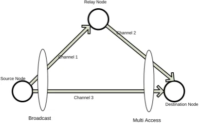
In wireless sensor networks, signal is severely degraded by the multipath signals which can be compensated with the use of diversity. Taking the advantageous of diversity, the destina-tion node accumulates or combines all the received signals received via independent links and makes the final decision upon the transmitted bits. This characteristic of sensor net-works is called the cooperative attempt and is always there when they are active. Sensor nodes, with this property en-hance their quality of service and offer good BER compare to the conventional mode of communication. The senor nodes make use of their processing capabilities to locally carry out simple calculations and send out only interested data [5]. This approach or capability of WPSN can offer spatial diversity against fading in a wireless channel4 [22]-[23]. If there is no direct line of sight or having difficulty in communication, then one sensor node help another, called relay node in order to accomplish transmission from source to the desired destina-tion [23]. This cooperative behaviour is adopted by each sensor node in the network along with the normal communi-cation responsibility.Node Cooperation results in various trades off in terms of resources e.g. data rate and transmit power. Because in cooperative mode if there are “N” number of sensor nodes, then the total power would be divided into “N” number of portions and with that individual part of the total power, the data would be transmitted to each node. Hence, total power available at the single node divided and thus it is reduced for all users because of diversity [24].The scenario that this work will consider would assume that all nodes work in the same band and therefore the source node will behave in broadcast manner, while the destination node is
in multiple channel access modes as depicted in the following figure 1. Channel between each pair of node is independent and have random effect on data.
Broadcast Multi Access
Channel 1
Channel 2
Channel 3 Source Node
Relay Node
Destination Node
Fig 1: A 2 hops relaying system
Cooperative behaviour of sensor nodes created new ap-proaches to enhance the sensor lifetime, low cost and multi functional operation in the sensor field. This approach created spatial diversity against fading in a wireless channel. In the case of sever fading channel, the source node is assisted by the relay channel to reach the information to the destination. This is basically done by the node relaying protocol called AF and DF. If the received signal SNR is below the threshold, due to which transmission is made unsuccessful, therefore message is encoded, re-encoded and retransmitted towards the destination. This decision is taken by the relay node on the single bit feedback, broadcasted by the destination that is at least reliably received by the relay node. Information is either corrupted by Reflection, Scattering or Diffraction etc. or due to the Small Scale Fading effect of the channel.
2.
SYSTEM MODEL, APPROACH AND
ACHIEVED RESULTS WITH
DIS-CUSSION
[image:1.595.328.534.272.404.2]Ration Combining (MRC) [36],[37]. SYSTEM DESIGN:Data passed through each relay node would be passed through the process shown by the following block diagram but only if the serving relay is choosing DF mode for retransmission of the received signal.
Fig 2: Block diagram of a Digital Communication Process System
Block diagram shows that initially, the data source ran-domly generates bit stream of 0s and 1s. Data stream is passed through encoder. Half convolutional encoder would be used in system design, which will introduce redundant bits equal to the information bits i.e. each information bit would have one redundant bit. The encoded bits would be modulated using different modulation schemes e.g. BPSK, QPSK etc. The modulator would generate a set of finite time duration
wave-forms and will provide mapping between the encoder output and the generated set of waveforms. The modulated signal is passed through flat fade channel and channel state information is known at the receiver. Channel introduces multiplicative noise but at the receiver, the received signal is also distorted by the AWGN noise. At the receiver, the same modulation scheme is used to de-map the signal and user data is decoded from the de-mapped signal.
S
R1
D
Cha nnel
2, N oise
2
Ch annel3
, N oise3
r1,r3 MRC(r1,r3) r2
Ps
New Ps
Channel1, Noise1
r3 AF/DF
Fig
3: One Relaying node using either AF or DF
Results-1: One Relay Coded system using BPSK, QPSK
[image:2.595.59.270.544.699.2]and 8PSK schemes
Fig 4: One Relay outputs using BPSK
One Relay output using BPSK. The unity power is shared between relay and the destination node i.e. source transmits data towards relay and destination with half power.
Fig 5: One Relay outputs using QPSK
One Relay output using QPSK. The unity power is shared between relay and the destination node i.e. source transmits data towards relay and destination with half power.
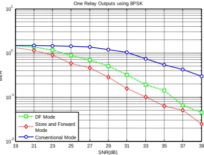
Fig 6: One Relay outputs using 8PSK
9 13 17 21 25 29 30
10-4 10-3 10-2 10-1 100
SNR(dB)
BER
One Relay using BPSK
DF Mode
Store and Forward Mode Conventional Mode
9 13 17 21 25 29 30
10-3 10-2 10-1 100
SNR(dB)
BER
One Relay Outputs using QPSK
DF Mode Store and Forward Mode Conventional Mode
19 21 23 25 27 29 31 33 35 37 39 10-2
10-1 100 101
SNR(dB)
BER
One Relay Outputs using 8PSK
DF Mode Store and Forward Mode Conventional Mode
Data
Source
Encoder
Modulator
Channel
DeModula-tor
User
Data
[image:2.595.321.525.581.735.2]One Relay output using 8PSK. The unity power is shared between relay and the destination node i.e. source transmits data towards relay and destination with half power.
Discussion of Results-1:Figure 4-6, show the bit error proba-bility of three types of transmission mode over a range of SNR. These are the outputs of a coded system using ½ rate convolutional code. The performance is observed over three types of different modulation schemes and throughout it is found that AF takes full advantage in terms of providing less transmission error compare to other two.
But there is obvious change in error probability when the number of sensor nodes increased. The reason is that, each sensor node has now more choices to achieve path diversity and to transfer the desired data over various paths. This offers more capability to combat fading and achieve.
When number of relay nodes increase, the serving node will equally distribute the total available power among all relay nodes and with that fraction of power, the data would be sent to each relaying node including destination node.
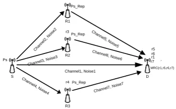
Power consumption should be at minimum if there are more relays available to help the serving node. This statement will also be proved at the end of this section. Moreover for comprehensive results, it is important to extend the model for multiple relaying nodes. The above model is for single relay, while in practical scenarios, a network consists of many relay nodes. Therefore, model is extended for multiple relays as depicted by the following diagram.
S R3 R2 R1 D Cha nnel 2, N
oise 2
Channel3, N oise3
Channel1, Noise1
Cha
nnel4, N
oise4
Cha
nnel5, N
oise5
Channe l6, Noise6
Channel 7, Noise7
[image:3.595.74.249.367.475.2]r5 r6 r1 r7 MRC(r1,r5,r6,r7) r2 r3 Ps Ps_Rep Ps_Rep r4 Ps_Rep
Fig 7: Diversity in Multiple nodes using Repeater Mode
In Figure 7, it is only one transmit antenna and 4 receive an-tennas. Each receive antenna has a distinct and independent experience of channel effect. The received data (r2, r3 and r4)
at relay R1, R2 and R3 is amplified by the corresponding power factors which are introduced by each relay node dis-tinctly.
At the destination, these are combined to evaluate the re-sultant SNR. Since each relay simply amplifies what they receive, therefore at the destination node, each received data is having the channel effect through which the received data had passed. Therefore, received data is equalized at the destination and then the user data is extracted after decoding. Mathemati-cal analysis for the repeater mode is as follow.
Suppose, Signals received by destination node and R1 as
1 , 1 , 1 , , , , R S R S S R S D S D S S D S
S
h
P
y
S
h
P
y
(1) 1 ,,D S R
S
and
y
y
correspond to r1 and r2 in above fig-ure. Each received signal has flat fad channel effect denotedby
h
S,Dand
h
S,R1and is different from each other. Eachtransmitted data is multiplied with a randomly varying
com-plex number
h
S,Dand
h
S,R1. Since the channelconsidered in this model is Rayleigh channel, therefore real and imaginary parts are Gaussian distributed with “mean = 0” and “variance = ½”. Also the noises are distinct on each link and are uncorrelated with respect to the noise received by each antenna.
Destination nodes receives signal via relay as
D R D R R S R S S R D R D R R S R D R
h
S
h
P
P
r
OR
h
y
P
y
, 1 , 1 1 , 1 , 1 , 1 , 1 1 , 1 , 1)
(
5
)
(
(2)Since the channel is known at the receive antenna, there-fore the destination node equalizes the two received signals and combine them as
D R R S D R R S R S
h
h
y
h
y
MRC
, 1 1 , , 1 1 , 1 ,*
(3)Substituting the values in equation 3
Rearranging the signal and noise part of the equation
D R R S D R D R R S R R S R S S R S
h
h
h
P
h
S
P
P
S
P
, 1 1 , , 1 , 1 1 , 1 1 , 1 , 1*
(4)Signal Power NoisePower
This is the combined signal of
r
1
andr
5
. However each signal passed through each relay path could be worked out in the same fashion.At the destination node, the received signal has the signal and noise power as shown in equation 4. The ratio of the ex-pectation of signal power to the exex-pectation of noise power gives SNR and could be written as.
D R R S D R R S R S R S S R Sh
h
h
S
P
P
S
P
SNR
, 1 1 , , 1 1 , 1 , 1 , 2 1*
(4.2.6) 0 2 1 2N
P
P
P
SNR
s
R S
(4.2.7)
In our system model since various SNR would be applied to see the error performance; the performance of which could be seen from equation above. As the SNR increases, the noise factor is dominated by the signal factor and thus error prob-ability is expected to be decreased constantly.
Each relay also has the choice to select the DF mode for retransmitting the received message as it could be seen in the
following diagram. S R3 R2 R1 D Cha nnel
8, N oise
8
Channel9, N oise9
Channel1, Noise1
Channe l10, N
oise10
Channe l11, N
oise11
Channel12, No ise12
[image:4.595.317.558.70.336.2]Channel13, N oise13 r11 r12 r1 r13 MRC(r1,r11,r12,r13) r8 r9 Ps Ps_DF Ps_DF r10 Ps_DF
Fig 8: DF Mode Diversity in Multiple nodes
Each relay in above diagram first decodes the signal. The decoded bits are retransmitted via the distinct channel to the final destination. At the destination node, four uncorrelated signals are received and equalized individually. The equalized signals are combined using MRC to evaluate the resultant SNR. Mathematical analysis for the DF mode is as follow.
In a most simple case, suppose the destination node in figure 8 receives two uncorrelated signals
r
1
andr
11
e.g.D R D R DF Ps D R D S D S S D S
S
h
P
y
r
S
h
P
y
r
, 1 ^ , 1 _ , 1 , , ,11
1
(6) Where ^S
are the information bits decoded by the relay node in advance. The relay node retransmits these bits with a new power factor represented by “Ps_DF”. The equalized signals are combined at the destination node such as.D R D R D R DF Ps D S D S D S S D R D R D S D S
h
S
h
P
h
S
h
P
h
y
h
y
r
r
MRC
, 1 , 1 ^ , 1 _ , , , , 1 , 1 , ,)
11
,
1
(
D R D R DF Ps D S D S Sh
S
P
h
S
P
, 1 , 1 ^ _ , ,
(7)Re-arranging the signal and noise part of the equation 7
D R D R D S D S DF Ps S
h
h
S
P
S
P
r
r
MRC
, 1 , 1 , , ^ _)
11
,
1
(
(8)
D R D R D S D S R Sh
h
S
P
S
P
SNR
, 1 , 1 , , 2 1
(9) 0 2 1 1 2N
P
P
SNR
s
S
R
R(10)
Results-2: 3 Relays Un-coded system with BPSK, QPSK
[image:4.595.83.260.340.464.2]and 8PSK
Fig 9: Three Relays outputs using BPSK
Three Relays outputs using BPSK. The unity power is shared among three relays and the destination node i.e. source
[image:4.595.332.527.370.520.2]trans-mits data towards relays and destination with one fourth power.
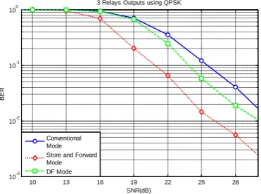
Fig 10: Three Relays outputs using QPSK
10 13 16 19 22 25 28 10-4 10-3 10-2 10-1 100 SNR(dB) 3 Relays Outputs using BPSK
Conventional Mode Repeater Mode DF Mode
10 13 16 19 22 25 28
10-3 10-2 10-1 100 SNR(dB) BER
3 Relays Outputs using QPSK
[image:4.595.336.522.603.741.2]Three Relays outputs using QPSK. The unity power is shared among three relays and the destination node i.e. source trans-mits data towards relays and destination with one fourth power.
Fig 11: Three Relays outputs using 8PSK
Three Relays outputs using 8PSK. The unity power is shared among three relays and the destination node i.e. source trans-mits data towards relays and destination with one fourth power.
Discussion of Results-2: Results showing very obvious changes when number of relays are increased i.e. the error probability decreases when relaying nodes are changed from one relay to three. For example in BPSK the BER in One relay is slightly above from 10-3 at 28dB, while the same bit error rate is achieved at nearly 25dBs in the case of three re-lays.
This could be further improved by the channel coding as it could be seen from the following results.
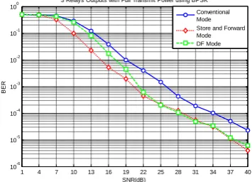
[image:5.595.61.263.127.280.2]Results-3: Channel Coding for 3 node relaying system using BPSK, QPSK and 8PSK.
Fig 12: 3 Relays outputs using ½ Convolutional Encoder
[image:5.595.332.529.258.424.2]Fig 13: Coded system of 3 relaying nodes
Fig 14: Coded system of 3 relaying nodes using 8PSK
Discussion of Results-3: Results were improved by the use of channel coding. Comparing figure 9 and 12, the same BER of 10-3 is achieved at 26dB in un-coded system, while in coded system; this is achieved at nearly 17dB SNR.
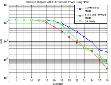
Results-4: 3 Relays outputs transmit data with total available power.
[image:5.595.67.271.475.627.2]The system performance was observed to be improved further when transmitted the received data with maximum power. If compare the results of figure 9 with 15, it would be found that error probability reduces nearly 1.5 times with full transmit power. The results with different modulation schemes could be observed from the following figure 15, 16 and 17.
Fig 15: 3 Relays transmission with total available power using BPSK
10 15 20 25 30 35 40
10-2 10-1 100 101
SNR(dB)
BER
Three Relays Outputs using 8PSK
Conventional Mode Store and Forward Mode DF Mode
5 10 15 20 25
10-6 10-5 10-4 10-3 10-2 10-1 100
SNR(dB)
BER
Coded system for 3 Relays using BPSK
Conventional Mode Store & Forward Mode DF Mode
1 5 9 13 17
10-5 10-4 10-3 10-2 10-1 100
SNR(dB)
BER
Coded system of 3 Relays using QPSK
Conventional Mode Store & Forward Mode DF Mode
1 5 9 13 17 21 25 29 30 10-5
10-4 10-3 10-2 10-1 100 101
SNR(dB)
BER
Coded scheme of 3 relays outputs using 8PSK Conventional Mode Store & Forward Mode DF Mode
1 4 7 10 13 16 19 22 25 28 31 34 37 40 10-6
10-5 10-4
10-3 10-2 10-1 100
SNR(dB)
BER
[image:5.595.339.517.594.722.2]Fig 16: 3 Relays transmission with total available power using QPSK
Fig 17: 3 Relays transmission with total available power using BPSK
3.
CONCLUSION
The cooperative system performance was investigated in chapter4 for two types of communication e.g. Cooperative communication with two relaying protocols and direct com-munication between source and destination. First of all, it has been proved from all graphs, the cooperative communication is always winning in multiple relays, no matter it is compared to AF or DF i.e. it provides low BER compare to un-cooperative communication, which provided that un-cooperative transmission offers spatial diversity against fading. Also it is reported that channel coding further improves the efficiency.
4.
REFERENCES
[1] Jennifer Yick, Biswanath Mukherjee, DipakGhosal, “Wireless Sensor Network Survey,” J.Yick et al./ Com-puter Networks 52 (2008), pp.2292-2330, April 2008. [2] X,-Y. Li; “Multicast Capacity of Wireless Ad Hoc
Net-works”, IEEE/ACM Transaction on Networking, vol.7, no.13, pp.950-961, June2009.
[3] G,-K. Chang, Z. Jia, J. Yu. A. Chowdhury, T. Wang, G. Ellinas, “Super-Broadband Optical Wireless Access Technologies,” OFC/NFOEC 2008.
[4] A. Bereketli and O. B. Akan, “Communication Coverage in Wireless Passive Sensor Networks,” IEEE Comm. Letters, vol. 13, no. 2, pp. 133-135, Feb. 2009.
[5] I.F.Akyildiz, W.Su, Y.Sankarasubramaniam, E. Cayirci, “Wireless Sensor Networks: A Survey ”Computer Networks 38 (2002), pp.393-422, Dec 2001.
[6] Alexander Becher, ZinaidaBenenson, and MaximillianDornseif, “Tampering with Motes: Real-World Physical Attacks on Wireless Sensor Networks,” pp. 1-15.
[7] Adrian Perrig, John Stankovic, David Wagner, “Security in wireless sensor networks,”Commun.ACM, 47(6), pp.53-57, 2004.
[8] Elaine Shi and Adrian Perrig, “Designing secure sensor networks,” IEEE Wireless Communications, 11(6), pp.38-43, December 2004.
[9] O. B. Akan, M. T. Isik, B. Baykal, “Wireless Passive Sensor Networks,” IEEE Comm. Magazine, vol. 47, no. 8, pp. 92-99, Aug. 2009.
[10] D. Sakamoto and H. Higaki “Wireless Multihop Transmission with Buffering in Neighbour Sensor Nodes for Short Delay,” IEEE Communications Society, WCNC 2009.
[11] Shi Yongjie, Sun Guiling, Liu Bo. Li Weixiang, “Design of Wireless Sensor Network Node Based on C8051F020 and CC1100 Fiber Bragg Grating,” IEEE, pp. 1-4.July 2010.
[12] C. Intanagonwiwat, R. Govindan, and D. Estrin, “Directed Diffusion: A Scalable and Robus Communication Paradigm for Sensor Networks,” Proc. ACM MobiCom ’OO, Boston, MA, 2000, pp. 56-57. [13] H. Stockman, “Communication by means of Reflected
Power,” Proc. I.R.E., vol. 36, 1948, pp.1196-1204.
[14] M. Kossel, H. R. Benedickter, R. Peter, Batchtold, “Microwave Backscatter Modulation Systems,” in IEEE MIT-S Digest 2000, pp.1427-1430.
[15] C.Turner, “Backscatter modulation of Impedance Modulated RFID tags,” pp. 1-5, Feb 2003.
[16] M. TalhaIsikOzgur B. Akan, “Padre: Modulated Backscattering-based Passive Data Retrieval in Wireless Sensor Networks,” IEEE Comm So, WCN 2009 Proc,.
[17] F. Kocer, P.M. Walsh, and M. P. Flynn. “Wireless Remotely Powered Telemetry in 0.25m CMOS,” Proc, IEEE RFIC, June 2004, pp. 339-342.
[18] Yanqiu Li, Hongyun Yu, Bo Su, and Yonghong Shang, “Hybrid Micropower Source for Wireless Sensor Network,” IEEE Sensors Journal,Vol 8, N0.6,June 2008, pp. 678-681.
[19] A. K. Marath, Y. W. M. Chia, C. C. Ko, “Performance Analysis of a Homodyne Receiver in Modulated Backscattered System for Intelligent Transportation.” IEEE 1999, pp. 1198-1202.
[20] K. Han, Y. Choi, S. Choi, and Y. Kwon, “Power Amplifier Characteristic aware energy efficient Transmission Strategy,” LNCS, vol.4479, pp. 37-48, Springer, Nov.2007.
[21] Product Datasheet “P2110-915MHz RF Powerharvester Receiver,”PowerCast, Rev A-2010/04, pp.1-12.
[22] M. R. Souryal, B. R. Vojcic, “Performance of Amplify-and-Forward and Decode-Amplify-and-Forward Relaying in Rayleigh Fading with turbo codes,”IEEE ICASSP, pp.IV-68-IV-684,2006.
1 4 7 10 13 16 19 22 25 28 31 34 37 40 10-5
10-4 10-3 10-2 10-1 100
SNR(dB)
BER
3 Relays Outputs with Full Transmit Power using QPSK Conventional Mode Store and Forward Mode DF Mode
1 4 7 10 13 16 19 22 25 28 31 34 37 40 10-3
10-2 10-1 100 101
SNR(dB)
BER
[image:6.595.76.266.256.401.2][23] J. Lee, S. Kim, H. S. T. Kwon, Y. Choi, J. S and A. Par, “Downlink Node Cooperation with Node Selection Diversity,” IEEE, 2005.
[24] N. Laneman, D. N. C. Tse, G. W. Wornell, “Cooperative Diversity in Wireless Networks Efficient Protocols and Outage Behavior,” IEEE Trans: on infor theory, vol,50, No, 12, pp. 2062-3080, 12 Dec 2004.
[25] A. Nosratinia, T. E. Hunter, A. Hedayat, “Cooperative Communication Wireless Networks,” Adaptive Antennas and Mimo Systems for Wireless Comm, IEEE Comm: Magazine, pp. 74-80, Oct 2004.
[26] N. Laneman, D. N. C. Tse, G. W. Wornell, “Cooperative Diversity in Wireless Networks Efficient Protocols and Outage Behavior,” IEEE Trans: on infor theory, vol,50, No, 12, pp. 2062-3080, 12 Dec 2004.
[27] J. G. Proakis, Digital Communication, 4thed. New York: McGraw-Hill, Inc., 2001.
[28] T. M. Cover and A. A. El Gamal, “Capacity theorems for the relay channel,” IEEE Trans. Infor, Theory, vol. IT-25, pp.572-584, Sept.1979.
[29] M. Yu and J. Li, “Is amplify-and-forward practically better than decode-and-forward or vice versa?”,Proc. IEEE Int. Conf. Acoustics, Speech, and Signal Processing (ICASSP). Vol. 3, pp.365-368. March 2005. [30] M-S. Alouini, A. Goldsmith, “Capacity of Rayleigh
Fading Channels Under Different Adaptive Transmission and Diversity-Combining Techniques,” IEEE Trans: on Vehicular Tech:,Vol:48, No. 4, pp. 1165-1181, July 1999. [31] T. Sunaga, S. Sampei, “Performance of multi-level QAM
with post-detection maximal ration combining space diversity of digital land-mobile radio communications,” IEEE Trans: Vehicular Technology,Vol. 42, pp.294-301, Aug 1993.
[32] J. N. Laneman, “Cooperative Diversity in Wireless Networks: Algorithms and Architectures,” Ph.D. dissertation, Massachusetts Institute of Technology, Cambridge, MA, Aug. 2002.
[33] X. Bao, J. LI, “Efficient Message Relaying for Wireless User Cooperation: Decode-Amplify-Forward (DAF) and Hybrid DAF and Coded-Cooperation,” IEEE Trans: on Wireless Comm:,Vol. 6, pp. 3975-3985, Nov. 2007. [34] T. Q. Duong, H-J.Zepernick, “Hybrid
Decode-Amplify-Forward Cooperative Communications with Multiple Relays,” IEEE Comm: Soc: WCN 2009 Proc:,pp. 1-6
[35] C. R. C. M. Da Silva, M.D Yacoub, “A Generalized Solution for Diversity Combining Techniques in Fading Channels,” IEEE Trans: on Microwave Theory and Techniques, Vol. 50, No.1, pp. 46-50, Jan 2002.
[36] B.S. Paul, R. Bhattacharjee, “Maximal ratio combining of two amplify-forward relay branches with individual l inks experiencing Nakagami fading,” IEEE, pp.1-4, 2007.
[37] A. Sendonaris, E. Erkip, B. Aazhang, “User Cooperation diversity-part-1: system description,” IEEE Transactions on Comm:.Vol. 51, no.11, Nov 2003.
[38] A. Sendonaris, E. Erkip, B. Aazhang, “User Cooperation diversity-part-II: Implementation aspects and performance analysis,” IEEE Transactions on Comm:,vol.51, no.11, Nov 2003
[39] Product Datasheet “P2110-915MHz RF Powerharvester Receiver,”PowerCast, Rev A-2010/04, pp.1-12.
[40] http://www.rfwirelesssensors.com/2010/04/powercast-p2110-battery-free-wireless-sensor-node-2010-04-30/
[41] G. Hoblos, M.Staroswiecki, and A.Aitouche, “Optimal Design of Fault Tolerant Sensor Networks,” IEEE Int’l.Conf. Cont. Apps., Anchorage AK. Sept. 2000,PP.467-72.