Simulation and Synthesis of Combinational
Shifter using Reversible Gates
Ravish Aradhya H V
1, Rekha G
2, Muralidhara K N
3 1,2Department of Electronics and Communication Engg, R V college of Engineering, Bangalore 560 059,India.3Department of Electronics and Communication Engineering, PES college of Engineering,
Mandya571 401,India.
ABSTRACT
In today’s world, the complexity of the chip is increasing as more and more devices are being connected on a single chip. As the number of devices on the chip increases, the devices must be scaled so that they can be accommodated on a chip of small size. Due to the high density of the chip, the power dissipation increases demanding better power optimization methods. One of the methods to achieve power optimization is by using Reversible logic. It can be used in Low Power CMOS designs, Quantum Computing, Nanotechnology and Optical Computing.
The objective of this work is to design a Combinational Logic Shifterthat is most often found in digital systems, where they are used to move data bits to new locations on a data bus or to perform simple multiplication and division operations. The performance characteristics of the two proposed designsare verified using number of reversible gates, Garbage outputs and Quantum Cost. The performanceCharacteristics analysis is carried out in cadence digital design environment and CMOS implementation in cadence virtuoso.
Key Words
Feynman Gate, Fredkin Gate, Garbage output, Line cost, Low Power, Peres Gate, Power Optimization, Quantum Cost, Reversible Logic.
1.
INTRODUCTION
Low power has emerged as a principal theme in today's electronics industry. The need for low power has caused a major paradigm shift in which power dissipation is as important as performance and area. Portable devices demand many features to be integrated on a chip of small area and long lasting batteries. Hence the power consumed by portable devices must be less for good life of the batteries so that they do not have to be replaced again and again. Power optimization can be done at various abstraction levels in CMOS VLSI design. That is at
Device (Technology) level, Circuit level,Logic level, Architecture (System) level, Algorithmic level, etc. One such method at circuit logic level is energy recovery method, which employs reversible logic gates.
According to R. Landauer’s research [2], energy (heat) of KTln2 is dissipated for every Irreversible bit operation, where K is theBoltzmann’s constant (1.3807×10⁻²³
JK-1) and T is the operating temperature. For T equal to room temperature (300 K), KT ln2 is approximately 2.8×10⁻²¹ J, which is small but non-negligible. In 1973, C. H. Bennett[1,3] concluded that no energy would dissipate from a system as long as the system was able to return to its initial state from its
final state regardless of what occurred in between. It made clear that, for power not to be dissipated in the arbitrary circuit, it must be built from reversible gate. Reversible circuits are of particular interest in low power CMOS VLSI design.
A combinational shifter is a digital circuit that can shift a data bits in the specified direction at a rate faster than a conventional sequential shifter. It can be implemented as a sequence of multiplexers (mux), and in such an implementation the input of one mux is connected to the input of the next mux in a way that depends on the shift direction.
The combinational shifter has a variety of applications, including being a useful component in microprocessors. The shift unit attached to a processor transfers the output of the ALU onto the output bus. The shifter may transfer the information directly without a shift, or it may shift the information to the right or left. Provision is sometimes made for no transfer from the ALU to the output bus. The shifter provides the shift micro operations commonly not available in an ALU.
An obvious circuit for a shifter is a bidirectional shift-register with parallel load. The information from the ALU can be transferred to the register in parallel and then shifted to the right or left. In this configuration, a clock pulse is needed for the transfer to the shift register, and another pulse is needed for the shift. These two pulses are in addition to the pulse required to transfer the information from the shift register to a destination register.
The transfer from a source register to a destination register can be done with one clock pulse if the shifter is implemented with a combinational circuit. In a combinational-logic shifter, the signals from the ALU to the output bus propagate through gates without the need for a clock pulse. Hence, the only clock pulse needed in the processor system is for loading the data from the output bus into the destination register.
2.
LITERATURE SURVEY
and the above computation is termed adiabatic. In Adiabatic computing instead of dissipating power, reuse it for some other process. So there will be no energy loss in the form of heat dissipation. Adiabatic computing is suitable only when delay is not critical because in this the energy is traded with delay. Since the reduction in switching energy is linear in supply voltageAdiabatic switching is a promising approach for large capacitive load circuits [7]. For sufficiently low switching, adiabatic circuits consume low power than their conventional counterparts [7].Adiabatic switching is the better approach particularly for small Vdd values [7].Asymptotically zero energy can be obtained by using fully adiabatic circuits at the cost of complexity.Quasi adiabatic logics can be used with minimum energy loss and less complexity.
Landauer [1] has shown that for every bit of information lost in logic computations that are not reversible, KT ln2 joules of heat energy is generated, where k is Boltzmann’s constant and T the absolute temperature at which computation is performed. The amount of energy dissipation in a system increases in direct proportion to the number of bits that are erased during computation. Bennett [2] showed that KT ln2 energy dissipation would not occur, if a computation were carried out in a reversible way. Thus, a reversible operation ensures low energy dissipation. Since the energy dissipated in CMOS cells is proportional to the number of transitions, to the output load, and to the square of the operating voltage. Energy of E= ½CV2 is stored and this energy gets dissipated whenever switching occurs in conventional (irreversible) logic implemented in modern CMOS technology, we reduce the number of transitions, the capacitance, and the voltage [9]. There are a variety of considerations that must be taken into account in low-power design which include the style of logic, the technology used, and the logic implemented. Factors that were shown to contribute to power dissipation included spurious transitions due to hazards and critical race conditions, leakage and direct path currents, pre-charge transitions, and power-consuming transitions in unused circuitry [7].
Efficient charge recovery logic (ECRL) is proposed as a candidate for low-energy adiabatic logic circuit. Proposed logic shows four to six times power reduction with a practical loading and operation frequency range. The ECRL inverter chain shows 10–20 times power gain over a conventional inverter chain [4]. It has been shown that reversible logic helps in saving this energy using charge recovery process [6].
[image:2.595.338.513.580.703.2]Reversible computation in a system can be performed only when the system comprises of reversible gates. A gate is reversible, if there is a distinct output assignment for each distinct input and it has the same number of inputs and outputs. Thus, a reversible gate’s inputs can be uniquely determined from its outputs. Also, the input and output vectors have a one-to-one mapping. Direct fan-outs from the reversible gate are not permitted. Feedbacks from gate outputs to inputs are not allowed. A reversible gate with n-inputs and n-outputs is called an n x n reversible gate. Several reversible gates have been designed till date. Some prominent among them are the Feynman gate, the Toffoli gate, the Fredkin gate and the Peres gate [5]. By using NOT, CNOT, CCNOT and FREDKIN gates, any combinational and sequential systems can be built.
Figure 1: Conventional Combinational Logic Shifter using 4:1 mux
Sk. Noor Mahammad and KamakotiVeezhinathan [8] showed that a novel universal reversible logic gate (URG) and a set of basic sequential elements that could be used for building reversible sequential circuits, with 25% less garbage than the best reported in the literature. He showed that the reversible implementation consumes 29.23 times lesser power, 2.57 times more transistors, and 3.77 times more delay than its static CMOS counterpart.
3.
METHODOLOGY
3.1
Introduction to Combinational Shifter
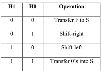
A Combinational-logic shifter can be constructed with multiplexers as shown in the Figure 1. The two selection variables, H1 and H0, applied to all four multiplexers to select the type of operation in the shifter. With H1H0=00, no shift is executed and the signals from F go directly to the S lines. The next two selection variables cause a shift-right operation and shift-left operation. When H1H0=11, the multiplexers select the inputs attached to 0 and as a consequence the S outputs are also equal to 0, blocking the transfer of information from the ALU to the output bits. Table1 summarizes the operation of the shifter.
3.2
Basic Reversible Gates
There are a number of existing 3x3 reversible gates such as the Fredkin gate, the Toffoli gate, the Peres gate and the Feynman gate. Each reversible gate has a cost associated with it called the quantum cost.
Table1: Functional Table for Shifter
The quantum cost of a reversible gate is the number of 1x1 and 2x2 reversible gates or quantum logic gates required in designing it. The quantum cost of all reversible 1x1 and 2x2 gates is taken as unity. Any reversible gate can be realized by using 1x1 NOT gate, and 2x2 reversible gates such as the
H1 H0 Operation
0 0 Transfer F to S
0 1 Shift-right
1 0 Shift-left
Controlled-V and the Controlled-V + and the Feynman gate which is also known as Controlled NOT gate (CNOT). Thus in simple terms, the quantum cost of a reversible gate can be calculated by counting the numbers of NOT, Controlled- V, Controlled-V + and CNOT gates used in implementing it.
Feynman Gate (CNOT Gate)
Figure2: CNOT gate and its quantum representation
Feynman gate (FyG) or Controlled-NOT gate (CNOT) is a 2 X 2 Reversible gate with inputs A, B mapping to outputs P=A, Q=A XOR. Since it is a 2x2 gate, it has a quantum cost of 1. Figure 2 shows the block diagram and quantum representation of the Feynman gate.
Toffoli Gate
[image:3.595.56.265.134.214.2]Toffoli Gate (TG) is a 3x3 two-through reversible gate asshown in Fig. 3(a). Two-through means two of its outputsare the same as inputs with the mapping (A, B, C) to (P=A,Q=B, R=AB xorC), where A, B, C are inputs and P, Q and Rare outputs, respectively. Toffoli gate is one of the mostpopular reversible gates and has quantum cost of 5 as shownin Figure3. The quantum cost of Toffoli gate is 5 as it needs2 Controlled-V gates, 1 Controlled-V+ gate and 2 CNOTgates to implement it.
Figure 3: Toffoli Gate and its quantum implementation
Peres Gate
[image:3.595.317.541.173.254.2]Peres gate is a 3 inputs 3 outputs (3x3) reversible gatehaving the mapping (A, B, C) to (P=A, Q=A xor B, R=(A.B) xor C), where A, B, C are the inputs and P, Q, R are the outputs respectively. Figure 4(a) shows the Peres gate andFig. 4(b) shows the quantum implementation of the Peresgate (PG) with quantum cost of 4. The quantum cost ofPeres gate is 4 since it requires 2 Controlled-V + gates, 1Controlled-V gate and 1 CNOT gate in its design. In the existingliterature, among the 3*3 reversible gate, Peres gatehas the minimum quantum cost.
Figure 4: Peres Gate and its quantum implementation
Fredkin Gate
Fredkin gate is a (3x3) conservative reversible gate,having the mapping (A, B, C) to (P=A, Q=A’B+AC,R=AB+A’C), where A, B, C are the inputs and P, Q, R are the outputs, respectively. It is called a 3x3 gate becauseit has three inputs and three outputs. Figure 5(a) shows theFredkin gate and Figure 5(b) shows its quantum implementation with quantum cost of 5.
Figure 5: Fredkin Gate and its quantum implementation
3.3 Proposed Reversible Combinational Logic
Shifter
Two different forms of Reversible combinational shifter designs are proposed here and few more designs may be tried offering further optimization in terms of different costs. The main issues to consider during a design are quantum cost, gate cost and garbage outputs.
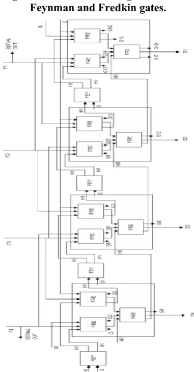
Design-1: Combinational Logic Shifter using
Feynman and Fredkin gates.
Figure 6: Design1-Reversible Combinational Logic Shifter using Feynman and Fredkin gates
FyG
G
P= A A
B
A
B
P
Q Q=A B
PG
P=A A
C R=AB C
B Q=A B
A
B
P
Q
V+
R
C V V
+
FG
P=A A
C R=AB C
B Q=A B
A
B
P
Q
R C
V V+
V+
TG
P= A A
C R=AB C
B Q=
B
A
B
P
Q
V+ V
R
[image:3.595.332.523.362.728.2] [image:3.595.63.277.441.500.2]The design of each 4:1Mux requires 1 FEYNMAN and 3 FREDKIN gates. This design requires a total of 16 gates. Each 4:1 mux has a total of 7 inputs which includes 4 variable inputs and 1 Constant input (Garbage Input-GI) and 2 select inputs. Constant inputs include a zero. Total number of outputs is 9; out of which 4 are garbage outputs (GO). The implementation of a 4-bit combinational shifter is shown in Figure 6 and may be extended to any number of bits.
Design-2: Combinational Logic Shifter using
Fredkin gates
The design requires four 4:1 Mux and each 4:1 mux is built using 3 FREDKIN gates. This design requires a total of 12 FREDKIN gates. The total number of inputs to each mux is 6 which include 4 variable inputs and 2 select inputs. Total number of outputs from each mux is 9, out of which 3 are garbage outputs. The implementation of a 4-bit combinational shifter is shown in Figure7 and may be extended to any number of bits.
Figure7: Design2- Reversible Combinational Logic Shifter using only Fredkin gates
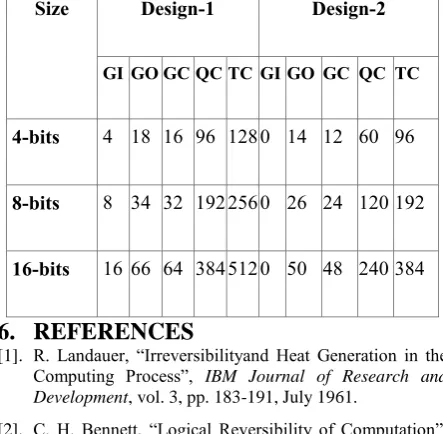
The implementation cost of variable size combinational shifter is shown in Table 6 and it is evident from the listing that design-1 offers better results and the number of garbage outputs may be obtained using Eq. 3.1.
𝐆𝐎 = (𝟑 𝐗 𝐧 + 𝟐) ………..Eq. 3.1
Here, n indicates the size of the combinational shifter to be implemented. It may be observed that design-2 has no constant inputs.
4.
Results
[image:4.595.311.533.74.406.2]4.1
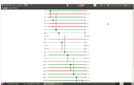
Results using RevKit Tool
[image:4.595.313.532.278.437.2]Figure 8: Simulation Results with H0=0 H1=0
Figure 9:Simulation Results withH0=0 H1=1
Figure 10:Simulation Results with H0=1 H1=0
Figure 11:Simulation Results withH0=1 H1=1
Parameter Results
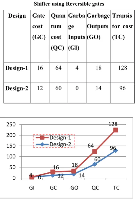
[image:4.595.314.532.465.603.2] [image:4.595.58.279.588.735.2]Table 2: Synthesis Results of 4-bit Combinational logic Shifter using Reversible gates
Design Gate cost (GC)
Quan tum cost (QC)
Garba ge Inputs (GI)
Garbage Outputs (GO)
Transis tor cost (TC)
Design-1 16 64 4 18 128
[image:5.595.328.531.308.760.2]Design-2 12 60 0 14 96
Figure 13: Comparison of proposed Combinational Shifter designs
4.2
Design implementation and simulation
in cadence virtuoso
Figure 13: Schematic of proposed Combinational Shifter using Fredkin gates
The simulation of the combinational shifter for design-2 is also performed using in cadence analog flow using gpdk180 technology library; the area report and the power report are generated.
Area report
The Area report for the proposed design is generated and listed in Table 3
Area report for the design using Fredkin gates only.
Generated by: Encounter(R) RTL Compiler v08.10-s121_1 (Oct 6 2008)
Module:rev_shifter
Technology library: gscl45nm
Operating conditions: typical (balanced_tree) Wireload mode: enclosed
4.3
Power report
The power report for the proposed design using Fredkin gate is generated and listed in Table 4.
Power report for the design using Fredkin
Generated by: Encounter(R) RTL Compiler v08.10-s121_1 (Oct 6 2008)
Module:rev_shifter
Technology library: gscl45nm
Operating conditions: typical (balanced_tree) Wireload mode: enclosed
Table 3: Area (μm2) of proposed design
Instance Cells Cell Area Net Area Total Area
shifter 48 123.9 0.00 123.9
shifter/m1 12 30.98 0.00 30.98
shifter/m1/m1 4 10.32 0.00 10.32
shifter/m1/m2 4 10.32 0.00 10.32
shifter/m1/m3 4 10.32 0.00 10.32
shifter/m2 12 30.98 0.00 30.98
shifter/m2/m1 4 10.32 0.00 10.32
shifter/m2/m2 4 10.32 0.00 10.32
shifter/m2/m3 4 10.32 0.00 10.32
shifter/m3 12 30.98 0.00 30.98
shifter/m3/m1 4 10.32 0.00 10.32
shifter/m3/m2 4 10.32 0.00 10.32
shifter/m3/m3 4 10.32 0.00 10.32
4 12 14
60 128
0
16 18
64 96
0 50 100 150 200 250
GI GC GO QC TC
[image:5.595.56.269.471.626.2]Instance Cells Cell Area Net Area Total Area
shifter/m4 12 30.98 0.00 30.98
shifter/m4/m1 4 10.32 0.00 10.32
shifter/m4/m2 4 10.32 0.00 10.32
[image:6.595.66.268.68.231.2]shifter/m4/m3 4 10.32 0.00 10.32
Table 4: Power (ηW) of design using Fredkin gate
Instance Cel ls
Leakage (nW)
Interna l (nW)
Net (nW)
Switchin g (nW)
rev_shifter
48 487.01 5125.2 0
3757.6
6 8882.85
rev_shifter/m1 12 121.75 1241.7
0 347.27 1588.97
rev_shifter/m1/
f1 4 40.58 392.39 139.75 532.15
rev_shifter/m1/
f2 4 40.58 327.00 130.07 457.07
rev_shifter/m1/
f3 4 40.58 522.31 77.44 599.75
rev_shifter/m2 12 121.75 1240.5
0 379.94 1620.44
rev_shifter/m2/
f1 4 40.58 425.10 177.26 602.37
rev_shifter/m2/
f2 4 40.58 327.00 130.07 457.07
rev_shifter/m2/
f3 4 40.58 488.40 72.60 561.00
rev_shifter/m3 12 121.75 1337.6
8 427.13 1764.81
rev_shifter/m3/
f1 4 40.58 327.00 130.07 457.07
rev_shifter/m3/
f2 4 40.58 457.82 214.78 672.59
rev_shifter/m3/
f3 4 40.58 552.86 82.28 635.14
rev_shifter/m4
12 121.75 1305.3
2 405.95 1711.28
rev_shifter/m4/
f1 4 40.58 392.42 188.76 581.18
rev_shifter/m4/
f2 4 40.58 359.70 134.91 494.61
rev_shifter/m4/
f3 4 40.58 553.21 82.28 635.49
Power and area parameters for both the designs are extracted
through Encounter(R) RTL compiler v08.10- s121_1 using
gsc145 nm Technology library and are tabulated in Table 5.
Table5:Power and Area analysis of both designs
Design-1 Design-2
Average Power (µW) 12.818 8.882
Total Area (µm2 ) 166.239 123.910
5.
CONCLUSIONS
[image:6.595.317.539.372.589.2]Parameters like Transistor cost, Quantum cost, gate cost, line cost and garbage outputs amongst the proposed design using RevKit are calculated.Good amount of reduction can be obtained in GATE COST by designing the Combinational Shifter using only “Fredkin” gates.
Table 6: Synthesis Results of n-bit Combinational logic Shifter using Reversible gates
Size Design-1 Design-2
GI GO GC QC TC GI GO GC QC TC
4-bits 4 18 16 96 128 0 14 12 60 96
8-bits 8 34 32 192 256 0 26 24 120 192
16-bits 16 66 64 384 512 0 50 48 240 384
6.
REFERENCES
[1]. R. Landauer, “Irreversibilityand Heat Generation in the Computing Process”, IBM Journal of Research and Development, vol. 3, pp. 183-191, July 1961.
[2]. C. H. Bennett, “Logical Reversibility of Computation”, IBM Journal of Research andDevelopment, pp. 525-532, November 1973.
[3]. E. Fredkin, T Toffoli, “Conservative Logic”, International Journal of Theoritical Physics, Vol. 21, 1982, pp.219-253.
[4]. Yong Moon et al, “An Efficient Charge Recovery Logic Circuit”, IEEE Journal of Solid-State Circuits, vol. 31, no. 4, April 1996.
[5]. D.P. Vasudevan, et al, “CMOS Realization of Online Testable Reversible Logic Gates”, Proceedings of the IEEE Computer Society Annual Symposium on VLSI New Frontiers in VLSI Design,0-7695-2365-X/05, 2005. [6]. HimanshuThapliyal, et al, “Transistor Realization of
Architectures”, Proceedings of the IEEE Computer Society Annual Symposium on VLSI New Frontiers in VLSI Design, 1-4244-0387-1/06, 2006.
[7]. William C. Athas and et al, “Low power digital systems based on adiabatic switching principles”,IEEE transactions on VLSI systems, V-2, Issue-4, Dec-1994. [8]. Sk.NoorMahammad and KamakotiVeezhinathan,
“Constructing Online Testable Circuits Using Reversible Logic”,IEEE Transactions on Instrumentation and Measurement, vol.59, No.1, January2010.
[9]. Mathew R. Pillmeier, Michael J. Schulte and E. GeorgeWaltersIII, “Design alternatives for barrel shifters”, Computer Architecture and Arithmetic Laboratory, Computer Science and Engineering Department, Lehigh University, Bethlehem, PA 18015,USA.
[10]. Irina Hashmi and Hafiz Md. HasanBabu, “An Efficient Design of a Reversible Barrel Shifter”,23rd International Conference on VLSI Design, 2010, pp.93-98.
[11]. Sabyasachi Das and Sunil P. Khatri, “A Timing-Driven Approach to Synthesize Fast Barrel Shifters”, IEEE Transactions on circuits and systems—ii: express briefs, vol. 55, no. 1, January 2008, pp. 31-35.
AUTHORS PROFILE
A. Ravish Aradhya H V born on March, 27th, 1969 in Karnataka, India, obtained his BE degree in Electronics from RV College of Engineering in 1991 and ME degree in Electronics from University Visvesvaraya college of Engineering, Bangalore, in 1995. Currently, he is an Associate professor at RV College of Engineering and a research student at PES college of Engineering, Mandya, in low power VLSI design area.He has Five Text books with McGraw-Hill (TMH) and Pearson Education, 10 International &16 National
papers to his credit. He has successfully guided many Post-graduate and UnderPost-graduate projects.
He is a life member in Indian Society for Technical Education (ISTE) and Institution of Electronics and Telecommunication Engineers (IETE). His research interests include the areas of VLSI design, Microprocessor and Microcontroller based system designs, Embedded system design, SOC design and Computer networking.
B. Rekha G born on March, 15th, 1990 in Karnataka, India, obtained her B.E degree in Electronics and Communication Engineering from Visvesvaraya Technological University (VTU), Belgaum, India. Currently pursuing M.Tech in VLSI Design and Embedded Systems. Her areas of interest are VLSI design and Embedded Systems.
C. Muralidhara K N born on March, 19th, 1959 in Karnataka, India, obtained his BE degree in Electronics and Communication from University of Mysorein 1981 and his ME and Ph.D. degrees in 1990 and 1998 respectively from Indian Institute of Technology, Roorkee (formerly known as University of Roorkee) Uttaranchal.
He is currently working as Professor and Head of the Department of Electronics and Communication Engineering, PES College of Engineering, Mandya, under Visvesvaraya Technological University. With over 30 years of teaching experience, professor is guiding 4 Ph.D students and guided many undergraduate and post graduate projects. To his credit; he got more than 20 International & National journals and papers.