© 2018, IRJET | Impact Factor value: 6.171 | ISO 9001:2008 Certified Journal | Page 2498
SEISMIC ANALYSIS OF VERTICAL IRREGULAR RC FRAMES WITH SHEAR
WALL AT DIFFERENT POSITIONS USING STAAD-Pro
Pushpendra Singh kushwah
1, Sachin Kumar Dangi
2, Dr. Aslam Hussain
31
PG Student, Dept. of Civil Engineering, UIT-RGPV Bhopal
2,3Assistant Professor, Dept. of Civil Engineering, UIT-RGPV Bhopal
---***---Abstract -
The greatest challenge for any structural engineerin today’s scenario is to design seismic-resistant structures. A regular building, i.e. having mass and stiffness uniformly distributed through its height behaves normally. The presence of vertical irregular frame subject to devastating earthquakes is a matter of concern. Points of sudden change in stiffness, mass and strength in buildings are known as weak points. It is essential to study the consequence of irregularity on the response of structure to lateral loads for the safety and design of irregular building. Here we study the proportional distribution of lateral forces evolved through seismic action in each storey level due to changes in mass and stiffness of frame on vertically irregular structures. The effect of mass and stiffness irregularity of G + 11-storeyed vertical geometric irregular building with shear wall are studied in zone IV in accordance with IS 1893:2002 part (1) using STAAD-PRO V8i software. Method of linear static analysis is used to evaluate response of the structure in the form of bending moment, base shear, lateral displacement and storey drift. Responses are plotted and compared; discussions and conclusions have been made from the results.
Key Words
:
Vertical Geometric
1, irregular buildings2, Seismic response parameters3, Shear Wall4, STAAD-Pro5, etc.1. INTRODUCTION
A natural disaster is a major adverse incident resulting from natural processes of the Earth which includes floods, hurricanes, tornadoes, volcanic eruptions, earthquakes, tsunamis, and other geologic processes. In which earthquake is the most terrible and unpredictable phenomenon of nature. Earthquake is the vibration of earth’s surface caused by waves coming from a source of disturbance inside the earth. As the waves radiate from the fault, they undergo geometric scattering and reduction due to loss of energy in the rocks. Since the interior of the earth consists of heterogeneous formations, the waves undergo multiple reflections, retraction, dispersion and reduction as they travel. The seismic waves arriving at a site on the surface of the earth are a result of complex superposition giving rise to irregular motion and shaking of ground.
1.1 Concept of vertical irregular geometric structure
It is seen that irregular structural configurations either in plan or in elevation were often recognized as one of the major causes of collapse during precedent earthquakes. In this study we are consider vertical irregularities in elevation. Vertical irregularities are described by vertical geometric discontinuity in the structure, distribution of mass, strength
and rigidity. Vertically irregular buildings such as stepped buildings are having discontinuities with respect to geometry.
Different types of vertical irregularities are as follows-
1.1.1 Stiffness Irregularity
a) Soft Storey
A soft storey is one in which the lateral stiffness is less than 70 percent of that in the storey above or less than 80 percent of the average lateral stiffness of the three storey above.
b) Extreme Soft Storey
A extreme soft storey is one in which the lateral stiffness is less than 60 percent of that in the storey above or less than 70 percent of the average stiffness of the three storey above.
1.1.2 Mass Irregularity
Mass irregularity shall be considered to exist where the seismic weight of any storey is more than 200 percent of that of its adjacent storey. The irregularity need not be considered in case of roofs.
1.1.3 Vertical Geometric irregularity
Vertical geometric irregularity shall be considered to exist where the horizontal dimension of the lateral force resisting system in any storey is more than 150 percent of that in its adjacent storey.
1.1.4 Discontinuity in Capacity - Weak Storey
A weak storey is one in which the storey lateral strength is less than 80 percent of that in the storey above. The storey lateral strength is the total strength of all seismic force resisting elements sharing the storey shear in the considered direction.
1.3 SHEAR WALL
© 2018, IRJET | Impact Factor value: 6.171 | ISO 9001:2008 Certified Journal | Page 2499 Reinforced concrete (RC) buildings often have vertical
plate-like RC walls called Shear Walls shown in Figure 6 in addition to slabs, beams and columns. These walls generally start at foundation level and are continuous throughout the building height. Their thickness can be as low as 150mm, or as high as 400mm in high rise buildings. Shear walls are usually provided along both length and width of buildings. Shear walls are like vertically-oriented wide beams that carry earthquake loads downwards to the foundation.
1.4 NEED OF THE STUDY
India is a developing country. Due to the economic and population growth in India, residential requirement is very high. Because of this reason construction of multistory buildings is increasing on plain as well as sloping ground. Irregular buildings behave different from those in plains when subjected to lateral loads due to earthquake. So we required the seismic analysis of the irregular building constructed on the hilly areas and also required to make this building earthquake resistant for safety purpose. Reinforced concrete framed buildings are adequate for resisting both the vertical and horizontal load acting on them. Vertical geometric irregularities mainly affect the height and configuration of building. By this comparative study we find out best configuration in seismic zone IV.
This study has been described to determine best configuration of building based on its linear behavior. A RC building (G+11 stories) with proper plan and elevation has been considered to carry out this study.
1.5 OBJECTIVES
The main objectives of this study are:-
1. To calculate the design lateral forces on irregular buildings using staad pro analysis and to compare the results of different structures.
2. To study three irregularities in structures namely mass, stiffness and vertical geometry irregularities.
3. To compare the behavior of RC building with shear wall and without shear wall on sloping ground.
4. To find the best position of the shear wall.
5. To calculate the response of buildings subjected to various types of ground motions mainly high frequency ground motion using staad pro analysis and to compare the results.
2. LITERATURE REVIEW
Shaikh Sameer and S. B. Shinde (September-October 2016)
The present paper attempts to investigate the proportional distribution of lateral forces evolved through seismic action in each storey level due to changes in mass of frame on vertically irregular frame. a G+10 vertically irregular building is modeled as an simplified lump mass model for the analysis
with mass irregularities at third & seventh floor. To response parameters like story drift, story deflection and story shear of structure under seismic force under the linear static & dynamic analysis is studied. This analysis shows focuses on the base shear carrying capacity of a structure and performance level of structure under sever zone of India. The result remarks the conclusion that, a building structure with mass irregularity provides instability and attracts huge storey shear. A proportionate amount of mass is advantageous to control over the storey and base shear.
T Berhanu (2016)
In this study, the importance of different bracing systems in the multistory RC frame structure a linear analysis of different story buildings are considered i.e., 4story (G+3), 6story (G+5), 9story (G+8), and 13story (G+12) of three bays by five bays RC building for seismic zone IV have been analyzed with four different types of steel bracing at the exterior of the frame in the same location and the same pattern. The bracings studied are diagonal brace, X-brace, V-brace and inverted V-V-brace (chevron V-brace) and performance of each frame has been carried out using linear static analysis. Two types of arrangements has been used;3x1braced (3bays out of 5 and 1bay out of 3 are braced) and corner braced (corners are braced in all direction) and all frames are analyzed without bracing and with all types of bracing, a total of 40 different models are analyzed and compared using nonlinear finite element software ETAB
Rana, D. and Raheem, J., (2015)
This work shows the performance & behavior of regular & vertical geometric irregular RCC framed structure under seismic motion. Five types of building geometry are taken in this project: one regular frame & four irregular frames. A comparative study is made between all these building configurations height wise and bay wise. All building frames are modeled & analyzed in software Staad Pro V8i. Various seismic responses like shear force, bending moment, storey drift, storey displacement, etc. are obtained. The seismic analysis is done according to IS 1893:2002 part (1). Seismic zone IV & medium soil strata are taken for all the cases. The change in the different seismic response is observed along different height. The seismic performance of regular frame is found to be better than corresponding irregular frames in nearly all the cases. Therefore it should be constructed to minimize the seismic effects.
3. MODELLING
STAAD-Pro Software is used for modelling of the building frame. For every structure a 3D model is developed. In the study we have considered a G+11 storey RC building on plan ground and 2 different position of the shear wall are used with bare frame.
Two different positions of shear wall used in this thesis are:- Shear wall at corner
© 2018, IRJET | Impact Factor value: 6.171 | ISO 9001:2008 Certified Journal | Page 2500 In this thesis, different configurations of building with and
without shear wall are analysed in seismic zone IV and different attempt has been made to find the best structure out of them. There are total 9 cases are modelled and analysed with the help of STAAD pro.
3.1 MODELLING DESCRIPTION
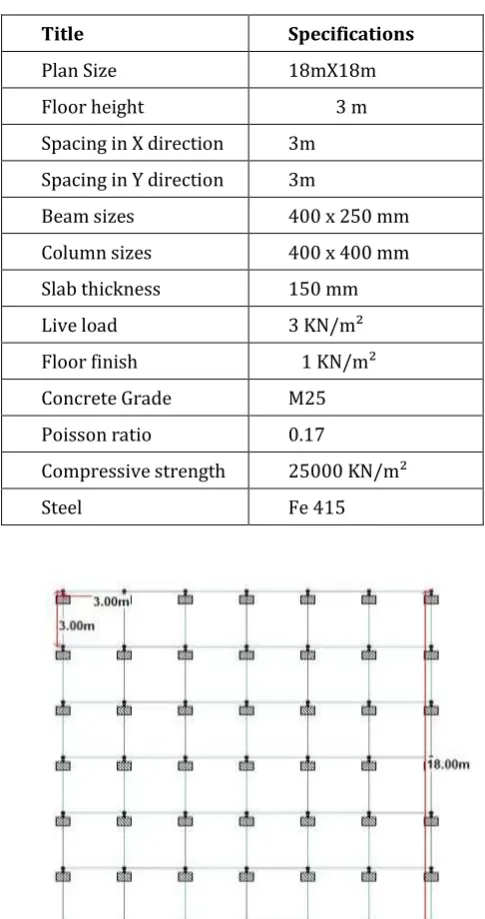
[image:3.595.328.537.124.305.2]A rectangular building considered for analysis is symmetric in plan and elevation. Plan dimension of the building to be modelled is 18mx18m. It consists of four bays of 3m each in longer and shorter direction respectively.
Table 3.1 Details and dimension of the building models
Title Specifications
Plan Size 18mX18m
Floor height 3 m Spacing in X direction 3m Spacing in Y direction 3m
Beam sizes 400 x 250 mm
Column sizes 400 x 400 mm
Slab thickness 150 mm
Live load 3 KN/m²
Floor finish 1 KN/m²
Concrete Grade M25
Poisson ratio 0.17
Compressive strength 25000 KN/m²
Steel Fe 415
Figure-3.1 Common plan for all building frame model
[image:3.595.42.533.234.753.2] [image:3.595.40.283.243.703.2]3.2 ELEVATION OF DIFFERENT CONFIGURATION OF THE BUILDING
[image:3.595.336.534.350.521.2]Fig. 3.1 Elevation and 3D view of Model 1
Fig. 3.2 Elevation and 3D view of Model 2
[image:3.595.340.527.556.744.2]© 2018, IRJET | Impact Factor value: 6.171 | ISO 9001:2008 Certified Journal | Page 2501
4. METHODOLOGY
The growth in computer processing power has made possible a continuous drive towards increasingly accurate but at the same time more complex analysis method. Thus the state of the art has progressively moved from elastic static analysis to dynamic elastic, non-linear static and finally nonlinear dynamic analysis.
In the present scenario, because of the wide range of geometry possible, the accumulated understanding is still limited, thus there is need of an attempt to investigate the behavior of vertical geometrically RCC building frame.
4.1 STEPS INVOLVED IN THE STUDY
This paper includes comparative study of behavior of structure with 12th storey frames with shear wall and with shear wall. A comparison in analysis results as displacement, moments, shear forces and storey displacement, base shear has been carried out as a result
Step-1 Selection of building frame i.e. G+11
Step-2 Selection of three different types of vertical geometry irregularities in structure with 3m storey height with same bay width 3m in both horizontal directions.
Step-3 Define the position of the shear wall (at corner, and middle)
Step-4 Selection of seismic zone IV Step-5 Formation of load combinations
Step-6 Modelling of building frame using STAAD Pro software
Step-7 Analysis of all the cases which are considered in the study
Step-8 Comparative study on basis of these parameters – Maximum Displacement
Maximum bending moment Maximum shear force Maximum axial force Base shear force
4.2 LOAD CALCULATION
4.2.1 Gravity load
For the Gravity loads on the structure include the self-weight of beams, columns, slabs and other permanent members. The self-weight of beams, columns (Frame members) and slabs (Area section) were automatically considered by the program itself.
Dead Loads: according to IS code 875 (part 1) 1987 Self-weight of structure
For G+11 Masonry wall Load
External Wall = 0.25 m x 2.5 m x 20 kN/m3 = 12.5 kN/m Internal Wall = 0.125 m x 2.5 m x 20 kN/m3 = 6.25 kN/m Live Loads: according to IS code 875 (part-2) 1987
Live Load = 3 kN/m2
Live Load on earthquake calculation = 0.75 kN/m2
4.2.2 Lateral load
For the lateral load analysis we use Static Method as per IS 1893 (Part1):2002
Seismic Loads:
Seismic calculation according to IS code 1893 (2002) Seismic zone- V
Zone factor: 3.6 Importance Factor: 1
Response Reduction Factor: 5 Damping: 5%
Soil Type: Medium Soil (Assumed)
Period in X direction (PX):0.09ℎ/√𝑑x seconds
(Clause 7.6.2)
= = 0.760 seconds
Period in Z direction (PZ): 0.09ℎ/√𝑑z seconds
(Clause 7.6.2)
= = 0.760 seconds Where h is the height of the building in meter
dx= dimension of building along X direction in meter dz = dimension of building along Z direction in meter
4.3 LOAD COMBINATION
Load case no. Load cases details
1. E.Q. IN X DIR.
2. E.Q. IN Z DIR.
3. DEAD LOAD
4. LIVE LOAD
5. 1.5 (DL)
6. 1.2 (DL + LL)
7. 1.5 (DL + LL)
8. 1.5 (DL + EQX)
9. 1.5 (DL - EQX)
10. 1.5 (DL + EQZ)
© 2018, IRJET | Impact Factor value: 6.171 | ISO 9001:2008 Certified Journal | Page 2502
12. 1.2 (DL + LL + EQX)
13. 1.2 (DL + LL - EQX)
14. 1.2 (DL + LL + EQZ)
15. 1.2 (DL + LL - EQZ)
16. 0.9 (DL) + 1.5 (EQX)
17. 0.9 (DL) + 1.5 (EQZ)
18. 0.9 (DL) - 1.5 (EQX)
19. 0.9 (DL) - 1.5 (EQZ)
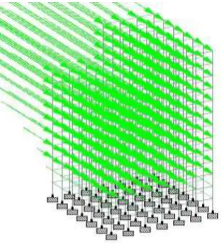
[image:5.595.311.536.197.340.2]4.4 LOADING CASES
Figure 4.1- Earthquake Forces in X direction
Figure 4.2- Earthquake Forces in Z direction
5. RESULT
All the irregular building frames with shear wall and without shear wall are analysed with the help of STAAD Pro software. All the models are analysed in the seismic zone IV. Using the analysis results various graphs are plotted and compared for all the models with different parameters.
For comparison following are the main parameters – Displacement
Shear Force
Axial Force Bending Moment
Base shear
5.1 MAXIMUM DISPLACEMENT
Maximum displacement of all the models in seismic zone-IV are shown in fig 5.1
0 20 40 60 80 100 120 140
Model 1
Model 2Model 3
BARE MODEL
SHEAR WALL AT CORNER
SHAER WALL AT MIDDLE
Figure No. 5.1- Maximum Displacement in X direction
From the results it is observed that maximum displacement is found in Model-3 in bare frame and minimum in Model-2 with shear wall.
We can observe that, node displacement is increased with irregularity of building.
It is obervered that shear wall reduces displacement, which is nearly equal in both locations in all models.
5.2 MAXIMUM SHEAR FORCE
[image:5.595.79.237.426.600.2]Maximum shear force for all model in seismic zone-IV are shown in fig 5.2
[image:5.595.311.557.572.741.2]© 2018, IRJET | Impact Factor value: 6.171 | ISO 9001:2008 Certified Journal | Page 2503 From the results it is observed that maximum shear
force found in Model-3 in bare frame and minimum in Model-2 with shear wall.
It is observed that, shear force is increased with irregularity of building.
It is observed that shear force is reduced in Model-2 with shear wall at middle.
5.3 MAXIMAUM AXIAL FORCES
[image:6.595.40.286.236.379.2] [image:6.595.313.563.275.434.2] [image:6.595.40.289.602.753.2]Maximum axial force of all models for seismic zone IV in fig.
Figure No 5.3- Maximum Axial Forces
From the results it is observed that maximum axial force is found in Model-3 in bare frame with shear wall at corner and minimum in Model-1 in bare frame.
We can observe that, axial force is increased with irregularity of building.
It is obervered that axial force increases with shear wall, maximum axial force found in shear wall at corner.
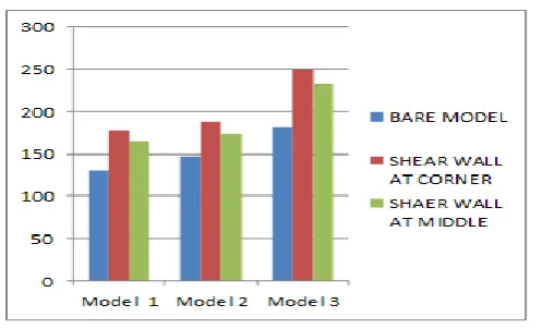
5.4 MAXIMUM BENDING MOMENT
Maximum bending moment of all models for seismic zone IV in fig 5.4
Figure No 5.4 Maximum Bending moment
From the results it is observed that maximum bending moment is found in Model-3 in bare frame with shear wall at corner and minimum in Model-1 in bare frame.
We can observe that, bending moment is increased with irregularity of building.
It is obervered that bending moment increases with shear wall, maximum bending moment found in shear wall at corner.
5.5 BASE SHEAR
Maximum base shear of all models for seismic zone-IV are shown in fig 5.6
4600 4800 5000 5200 5400 5600 5800 6000
Model 1 Model 2 Model 3
Bare frame
Shear wall at corner
Shear wall at middle
Figure No 5.5- Maximum Base Shear
From the results it is observed that maximum shear force found in Model-1 in bare frame and minimum in Model-3
It is observed that, base shear is reduced with irregularity of building.
It is observed that base shear does not affected by shear wall.
6. CONCLUSIONS
Based on static analysis of the different configurations of the irregular building the following conclusions are drawn-
In this study, results are decreases with irregularities in base shear and storey drift and results are increases with irregularities in displacement, shear force, axial force, bending moment.
© 2018, IRJET | Impact Factor value: 6.171 | ISO 9001:2008 Certified Journal | Page 2504 There is significant improvement observed in
seismic performance of the irregular building by providing shear walls with different configurations since lateral displacement and member force reduce considerably in building due to provision of shear walls.
It is observed that maximum displacement found in maximum irregular structure of bare frame hence we can say that risk increases with irregularities.
In this study we found that, the position of the shear wall at corner is the best position for the lateral resisting system
REFERENCES
[1] Shaikh Sameer, J. and Shinde, S.B., Seismic response of vertically irregular RC frame with stiffness irregularity at ground floor.
[2] Berhanu, T., 2016. Comparative Study on the Response of RC Frame Structure Braced With Different Steel Bracing Systems (Doctoral dissertation, AAU).
[3] Rana, D. and Raheem, J., 2015. Seismic Analysis of Regular & Vertical Geometric Irregular RCC Framed Building
[4] Vijayakumar, M., Manivel, M.S. and Arokiaprakash, M.A., 2015. A Study on Seismic Performance of RCC Frame with Various Bracing Systems using Base Isolation Technique. International Journal of Applied Engineering Research, 11(10), pp.7030-7033
[5] IS 1893 : 2002, Indian Standard criteria for earthquake resistant design of structures, Part 1General provisions and buildings, Draft of Fifth Revision, Bureau of Indian Standards, New Delhi, 2002.
[6] IS: 456-2000., “Code of Practice for Plain and Reinforced Concrete”, Bureau of Indian Standard, New Delhi, India.