MULTIOBJECTIVE BUILT IN SELF REPAIR ALGORITHM
WITH MULTIPLE FAULT DETECTION FOR
RECONFIGURABLE SYSTEMS
1 PRADEEP C 2 R. RADHAKRISHNAN 3
NEENA BABY 4 PHILIP SAMUEL
1,3
Department of ECE, SAINTGITS College of Engineering,Kottayam,India
2
Principal, Vidhya Mandhir Institute of Technology,Erode,India
3
Department of ECE, SAINTGITS College of Engineering,Kottayam,India
4
Division of IT, Cochin University of Science and Technology, Cochin,India
Email: [email protected], [email protected], [email protected], [email protected]
ABSTRACT
Field Programmable Gate Arrays (FPGAs) are widely used in reliability-critical applications due to their reconfiguration ability. The emergence of partial reconfiguration in FPGAs has made it possible to incorporate fault tolerance into systems more easily. Fault tolerance includes fault detection and fault recovery. This paper presents the investigation of a fault detection and repair algorithm. Currently available self-repair algorithm makes use of large number of spare cells to achieve good fault coverage.This limitation is overcomed by the proposed algorithm, MORe which satisfies multiple objectives such as less area, minimum routing overhead and multiple fault detection capability.The MORe algorithm is demonstrated and compared with the other two existing algorithms using Matlab.
Keywords: - Field Programmable Gate Arrays (FPGAs), Fault Recovery, Self-repair, Transient fault, Permanent fault, Spare cell.
1. INTRODUCTION
FPGA faults are generally classified as transient and permanent faults.Transient Faults in FPGA are caused by temporary environmental
conditions, such as cosmic rays and
electromagnetic interference and exists only for a short duration. Permanent faults continue to exist until the faulty component is repaired. They are caused by irreversible device and circuit changes, such as electro migration, hot carrier effect and time dependent dielectric breakdown. Burnt-out chips, software bugs and disk head crashes are examples of permanent faults.
Fault tolerance refers to a system that can provide its services even in the presence of faults.
To guarantee failure-free operation, some
established principles are still applied by the engineers to ensure continued operation in the presence of fault. Here, quality of the system operation decreases proportionally with the severity of the fault and the system continues to operate at a reduced level of service rather than failing completely.
Inspired from molecular biology, the concept of self-repairing systems was first proposed in
1990s. Since then, an increased attention was given to self repairing digital systems, as modern digital systems are getting more fast and complex [8]. In self-repairing systems, cells without any function are initially implemented as logic blocks or routing resources and are programmed later in case of failure to replace faulty cells. In contrast, hardware redundancies should be made in advance in fault-tolerant systems. The applications of self-repair include mission critical digital systems, avionics, medical electronics, space probes etc.
area and minimum routing overhead can also be achieved by using MORe.
The rest of the paper is organized as follows. Section 2 deals with the related research works in this area. The proposed fault recovery procedure is discussed in section 3. Experimental setup is described in section 4. Results and performance matrix is given in section 5. Conclusion of this research work and scope for future work is discussed in section 6.
2. PREVIOUS WORKS
Tandem and Stratus devised a fault tolerant
system based on physical redundancy [1]. Here,
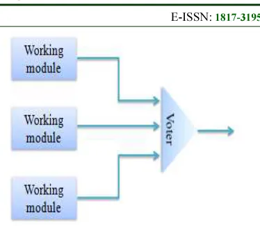
extra equipment or processes are added to make it possible for the system as a whole to tolerate the loss or malfunctioning of some components. Consider a circuit in which signals pass through the devices in sequence. If one of the devices is faulty, the final result will probably be incorrect. To alleviate this problem, each device is replicated three times as shown in Fig. 1. Each stage in the circuit is followed by a triplicate voter. Voter is a circuit that has three inputs and one output. If two or three of the inputs are same, the output is equal to that input. If all three inputs are different, the output is undefined. This kind of design is known as Triple Modular Redundancy (TMR). The main drawbacks of this technique are area overhead and high implementation cost.
[image:2.595.319.506.105.268.2]Computer architecture with many cores for fault detection and recovery was designed using partial reconfiguration of an FPGA [2]. The entire FPGA is divided into tiles which contain homogenous soft processors. The three processors are configured in TMR to detect faults. The faulty tiles are replaced by spare processors. An SEU in the FPGA and configuration RAM is mitigated using a reset sequence and partial reconfiguration of the tile respectively. TID damage in a tile is mitigated using partial reconfiguration of the tile. This design allows fault recovery both in circuit fabric and configuration RAM of FPGA. Also, it permanently avoids damaged regions of the chip.
Figure 1: Triple Modular Redundancy
The restrictions of fault recovery using intrinsic reconfiguration were described by Greenwood [3]. Evolvable hardware (EHW) is a viable method of performing fault recovery in systems without redundant hardware. Previous EHW research relating to fault-tolerance primarily focused on restoring functionality, with no consideration of time constraints. But, the device programming time, the fitness evaluation time and the EA overhead time must be considered on attempting to intrinsically evolve a new hardware configuration because they all contribute to the reconfiguration time. Intrinsic reconfiguration can be used for fault recovery so long as it finishes before the mandatory recovery deadline. It may also be possible to do the recovery in stages rather than all at once.
The FPGA is partitioned into self-testing area and working area in the roving self-testing areas (STARs) approach [4]. BIST and fault diagnosis is done in STAR whereas the functionality of the system operates in the working area. The fault is detected in STAR and the normal system function is not interrupted. The STAR roves to a new location after testing and make sure that the entire FPGA is tested. Here no additional system function downtime is required for fault tolerance and the faulty Programmable Logic Block (PLB) can be reused.
were applied to the 2-D world of silicon integrated circuits [5]. The concept leads to a cellular array-based fault-tolerant electronic system with online self-test and self-repair capability.
Self-propagation and self-healing
characteristics of biological systems was used in the design of digital systems [6], [7]. The architecture consists of router cells, functional cells and spare cells. Each functional cell is surrounded by two spare cells. When a functional cell becomes faulty, a suitable spare is used to replace the faulty cell. The spare cells and router cells have an additional decision making circuitry to decide which spare cell to replace a faulty cell.
A novel self-repairing architecture was proposed for fast fault recovery with efficient utilization of limited resources [8]. The architecture was inspired from the concept of paralogous genes. A working module consists of 16 working cells, 16 redundancies and 4 stem cells. Each working cell has its own fault detection circuit. Here the normal operation is immediately restored by replacing a faulty working cell by its redundancy. Each functional cell has a spare and the inputs are pre-routed to both. This still requires an external router to decide which cell need to be active either the original cell or the spare cell. In case of a permanent fault, the stem cells which are initially empty become redundant for any working cell. However, the architecture fails if a permanent fault occurs in the absence of a spare cell.
An efficient fault recovery algorithm using king spare allocation technique and Dijkstra’s shortest path shifting was proposed in [9]. Eight working cells and one spare cell together constitute a section. Whenever a fault is detected in a working cell, the spare differentiates as the working cell if the corresponding section spare is available. Then the faulty cell undergoes self-test to identify the type of fault. If it is a transient fault, the faulty cell is recovered and dedifferentiated as the working cell. But in case of permanent fault, the faulty cell undergoes apoptosis. If the corresponding section spare is not available, the faulty cell undergoes delayed recovery in case of transient fault. But if the fault is permanent, Dijkstra’s shortest path algorithm is used to determine the shortest path to the available spare in other sections. After determining the shortest path,
all the cells in the path are checked to determine whether they are fault free. The shifting of cells is performed if the shortest path is fault free else the second shortest fault free path is identified and so on. Here also, the algorithm cannot handle a permanent fault in the absence of a spare cell.
3. PROPOSED WORK
The proposed self-repair algorithm can be
implemented in FPGAs using partial
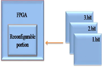
[image:3.595.318.498.350.471.2]reconfiguration. Partial reconfiguration is a process of changing a portion of the reconfigurable hardware while the remaining part is still working. As shown in Fig. 2, the functionality implemented in the reconfigurable portion is modified by downloading one of the partial bit files, 1.bit, 2.bit, 3.bit.
Figure 2: Partial Reconfiguration
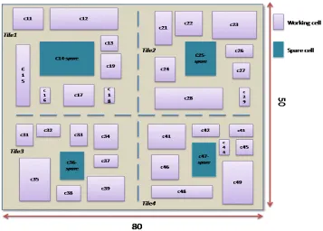
An FPGA having size 100x80 and
Figure 4: FPGA Simulation model for existing algorithms.
[image:4.595.119.476.433.689.2]However in the proposed algorithm, the working cells can be of different size. When a working cell in a particular section becomes faulty and if a spare of suitable size is available in that section, then that spare is differentiated to replace the faulty cell regardless whether the fault is transient or permanent. But if a spare of suitable size is unavailable in a particular section, then self test is first performed. If the fault is transient, then the cell undergoes delayed transient fault recovery else Shortest Path Allocation Repair algorithm [9] is performed. Even if a spare cell of appropriate size is not available in any of the sections, the proposed algorithm can handle it by satisfying multiple objectives such as less area and minimum routing overhead. Hence the algorithm is named as Multi-Objective Repair algorithm (MORe). Here, the system continues to operate at a reduced level of performance rather than failing completely and thus the system can be retained for a longer duration. A fault that occurs in a tile can be either a logic fault or an interconnect fault. Logic fault occurs within a cell and interconnect fault occurs in the via between two cells. Separate hardware circuitry is used to handle both logic and interconnect faults.
3.1 Multi Objective Repair Algorithm
Here, the system continues to operate at a reduced level of performance rather than failing completely and thus the system can be retained for a longer duration. Some of the definitions of proposed algorithm are as follows:
Definition 1 Cell
A cell with index i is defined as a 3-tuple
Celli = (P , Rc , A) such that:
• P is the priority of a cell.
• Rc is the routing complexity of a cell.
• A is the size of a cell.
Definition 2 Priority (P)
The priority of Celli is defined as the
importance of the cell. If a system cannot function
without a cell, then that cell is assigned with high priority and if a system can function without a cell at a reduced level of performance, then that cell is assigned with low priority.
Definition 2 Routing (Rc)
The routing of Celli is defined as the
path that connects it with other cells. The shortest path between two cells can be determined by SPARe algorithm.
Definition 3 Size (A)
The size of Celli is defined as the area
occupied by the cell in the entire FPGA. The functionality of a cell can be replaced by another cell having area equal to or greater than the current cell. The following constraints are defined to recover the FPGA from further permanent faults.
a. The entire FPGA is grouped into different
sets of cells having the same area.
b. The parameters of a cell are assigned with
different weights, i.e., P, Rc and Swith first, second and third respectively.
Algorithm description
The pseudo code of the MORe algorithm given in algorithm 1 is an extension of the Shortest Path Allocation Repair algorithm proposed in [9]. In this algorithm the system sustains even in the absence of a spare cell. Also, MORe algorithm satisfies multiple objectives such as cell size checking , redundant cell usage and minimum routing overhead. This algorithm considers the priority of the working cells to make the system survive in the absence of a spare cell. On detecting a fault by online fault detection mechanism, i.e., fault info = 1, the availability of a section spare and the size of the available spare cell with respect to the faulty cell is checked. If a section spare is available and the size of the spare is greater than or equal to the size of the faulty cell, the corresponding spare differentiates as the working cell and the faulty cell undergoes a fault identification test. If the result of the test ‘Tf’ = 0 corresponds to a permanent fault or otherwise, a transient fault.
and the faulty cell undergoes apoptosis, otherwise. If a fault occurs in the absence of a spare cell, the availability of redundant cells is checked. The faulty cell undergoes apoptosis, if it has got the least priority. Otherwise, the cell with least priority differentiates as the working cell. The count of
redundant cells is then decremented and this continues until the entire redundant cells in the system are utilized. If a permanent fault occurs in the absence of a redundant cell, the system functionality stops.
Algorithm 1: Pseudo code of MORe
fault info ->output from online fault detection mechanism
Ss -> Section spare cell for differentiation
Si ->Set of spare cells in the system
Pi ->Priority of celli in the system
Ri ->Set of redundant cells in the system
As ->Size of section spare cell for differentiation
Af ->Size of faulty cell
Fd ->faulty cell
Tf ->output of fault identification system
(Tf = 0 for permanent fault and Tf = 1 for transient fault)
Algorithm “MORe” ( )
input: Pi, Ri, Ai , fault info, Fd, As,Af,Si result msg1, msg2
1:whilefault info = 1do
2:search for spare Si
3:If Cell Ss≠ 0 & As >= Af then
4: Shortest Path Allocation Repair Algorithm ( ) /* Algorithm in [9]*/
5:skip to step 18 6:else
7:if Ri ≠ 0 then
8:if Pi ( Fd ) = 0 then
9:Cell Fd=apoptosis 10:else
11:Search for cell with lowest Pi 12:Si = cell with lowestPi
13:Decrement Ri
14:end if
15:go to step 3 16:else
17:print msg “further fault correction not possible” 18end if
19:end while.
By using MORe algorithm, more number of permanent faults can be recovered but at the expense of decreased performance. This algorithm can be used until all the cells in the dynamic module (extra features that are added without which the system can work) undergo apoptosis and the static module alone works.
4. EXPERIMENTAL SETUP
number of transient faults and four permanent faults. The area overhead of the algorithm is compared with other algorithms. The detailed explanation of simulation of each algorithm is given in the following session.
5. RESULTS AND DISCUSSIONS
The proposed and existing algorithms are simulated using Matlab by creating an FPGA image with size 100x80 and fixing the reconfigurable portion of 80x50. The rest of the FPGA area is used for the static part of the Dynamically Reconfigurable System. Two more existing algorithms are also simulated on the similar procedure for the comparative study. The cell replacement and rerouting process of the proposed system is different from that of the previous works. The functional and spare cells of MORe algorithm is variable but it is fixed in the other two algorithms taken for study.
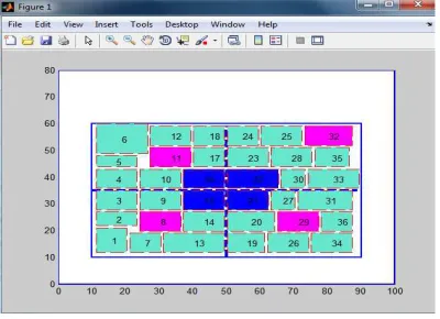
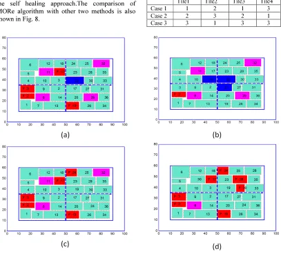
Here 9 cells comprise a tile and the working, redundant and spare cells are taken with variable sizes. The working cells and spare cells are labeled using numbers starting from 1 to 36. Cells 15, 16,21 and 22 are labeled as spare cells and cells 8, 11, 29 and 32 are taken as the redundant cells in this simulation. The remaining cells are taken as the working cells as shown in Fig. 6. Since the cells are of variable size, the substitution for self repair on occurrence of a permanent fault in the absence of a spare cell is carried out only if the spare or redundant cells are equal or greater in size than the faulty cell. All the situations are considered in this simulation only if the size is matching.
Figure 6: Variable size cell arrangements for “MORe” algorithm simulation with redundant
cells
When a permanent fault is introduced into cell 2, the spare cell 15 immediately takes the functionality of the faulty cell. The faulty cell 2 is marked as F and colored red as shown in Fig. 7 (a). On introducing 2nd and 3rd permanent faults into cells 3 and 17 respectively, spare cells 16 and 21
takes the functionality of faulty cells and 4th
permanent fault is introduced into cell 19 as shown in Fig. 7 (b). Then the spare cell 22 takes the functionality of the faulty cell 19. All the spare cells are differentiated as working cells and further permanent faults will be handled by the redundant
cells. When a 5th permanent fault is introduced into
cell 24, the functionality of cell 29 which has got the least importance is neglected and the same cell takes the functionality of cell 24 as shown in Fig. 7
(c). 6th and 7th permanent faults in cells 28 and 30
are handled by the redundant cells 32 and 11 respectively as shown in Fig. 7 (d). 8th permanent fault will be handled by the redundant cell 8 and the system cannot handle any more permanent faults. All the cell differentiation takes place by considering the size of the cells.
The maximum number of permanent faults that can be repaired by MORe algorithm with redundant cells in the system are equal to the sum of spare cells and redundant cells. In this simulation, the system consists of only 4 spare cells and 4 redundant cells and hence the maximum permanent faults that can be repaired are 8. When the 9th fault is introduced, the algorithm fails and the system stops its working.
The MORe algorithm is simulated with various numbers of redundant cells. The details of redundant cells in three different cases are given in Table 1. and the details of simulation parameters used are given in Table 2. The simulation results are given in Table 3. MORe algorithm with three different cases of redundant cells are compared with the other two algoritms and in all the three cases, the number of permanent faults that can be repaired is more than that of ther two methods while keeping the area overhead constant.The only limitation is the degradation in the throughput of
the system.The degradation level can be
maintained by carefull design of the reconfigurable system modules and assigning low level functions to the redundant cells.The simulation is stopped in each cases when the algorithm fails, i.e., algorithm is not capale of repair the existing permanent faults.
[image:7.595.90.290.542.687.2]MORe. All the three algorithms are capable of repairing infinite number of transient faults. Area utilization is same for all the algorithms except for the self healing approach.The comparison of MORe algorithm with other two methods is also shown in Fig. 8.
Table 1: Details of redundant cell in tiles
Tile1 Tile2 Tile3 Tile4
Case 1 1 2 1 3
Case 2 2 3 2 1
Case 3 3 1 3 3
[image:8.595.90.504.583.721.2]Figure 7: Permanent fault recoveries of cells with variable size
Table 2: Simulation parameters used in the comparative study
Parameter MORe Algorithm in [9] Self Healing System
Reconfigurable Area 80*50 80*50 80*50
Number of Tiles 4 4 4
Number of Functional Cells/Tile 8 8 4
Number of Spare Cell/Tile 1 1 5
Table 3: Details Of Simulation Results
Item MORe
Algorithm [9]
Self Healing System
case 1 case 2 case 3
Number of Transient Faults Introduced 15 15 15 15 15
Number of Transient Faults Repaired 15 15 15 15 15
Number of Permanent Faults Introduced 8 10 6 4 0
Number of Permanent Faults Repaired 7 9 5 4 0
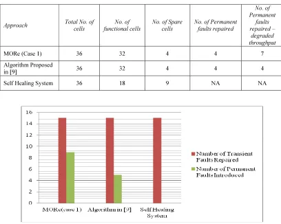
[image:9.595.92.500.328.654.2]Algorithm Failure at Permanent Fault No. 8 9 6 5 1
Table 4: Hardware Comparison Of Three Architectures
Approach Total No. of
cells
No. of functional cells
No. of Spare cells
No. of Permanent faults repaired
No. of Permanent
faults repaired –
degraded throughput
MORe (Case 1) 36 32 4 4 7
Algorithm Proposed
in [9] 36 32 4 4 4
Self Healing System 36 18 9 NA NA
Figure 8: Comparison More Algorithm With Other Methods
6. CONCLUSION
A self repair algorithm with increased number of permanent faults repair is presented in this paper. The proposed algorithm satisfies multiple
The existing algorithms cannot handle the occurrence of a permanent fault in the absence of a spare cell. However, the proposed algorithm differs with other two methods by ensuring the system operation with a degraded throughput even if there is no spare cell exists in the system. The number of permanent faults that can be repaired by the proposed algorithm is more as compared to existing methods. The algorithm also checks the compatibility of faulty cell with the spare cell
before replacement.This algorithm can be applied
to any modern FPGA that has dynamic Partial Reconfiguration (DPR) capability. DPR allows to modify parts of the design of the operating
FPGA without affecting the other parts.
The drawback of the algorithm arises when a permanent fault occurs in the absence of a least priority module. Also, the algorithm results in a degraded throughput. The future goal is the implementation of the proposed MORe algorithm using PlanAhead 14.2 on Virtex-5 devices which supports partial reconfiguration.
REFERENCES
[1] R. E. Lyons and W.Vanderkulk, “The use of
triple-modular redundancy to improve
computer reliability,” IBM J., vol. 6, no. 2, pp. 200–209, Apr. 1962.
[2] Clint Gauer, Brock J. LaMeres and David Racek,
Electrical & Computer Engineering
Department, Montana State University,
Bozeman, MT 59717, “Spatial Avoidance of
Hardware Faults using FPGA Partial
Reconfiguration of Tile-Based Soft
Processors”.
[3] Garrison W. Greenwood, Senior Member, IEEE, “On the Practicality of Using Intrinsic Reconfiguration for Fault Recovery,” IEEE Transactions on Evolutionary Computation, Vol. 9, No. 4, August 2005.
[4] J. M. Emmert, C. E. Stroud, and M. Abramovici, “Online fault tolerance for FPGA logic blocks,” IEEE Trans. Very Large Scale Integr. (VLSI) Syst., vol. 15, no. 2, pp. 216–226, Feb. 2007.
[5] Mohammad Samie, Gabriel Dragffy, Andy M. Tyrrell, Senior Member, IEEE, Tony Pipe, and Paul Bremner, “Novel Bio-Inspired Approach for Fault-Tolerant VLSI Systems,” IEEE Transactions on Very Large Scale Integration (VLSI) Systems, Vol. 21, No. 10, October 2013.
[6] P. K. Lala, B.K. Kumar, “An architecture for self-healing digital systems,” J. Electron. Test.: Theory Appl., vol. 19, no. 5, pp. 523-535, Oct. 2003.
[7] P. K. Lala, B.K. Kumar, and J. P. Parkerson, “On self-healing digital system design,” ELSEVIER Microelectron. J., vol. 37, no. 4, pp.353-362, Apr. 2006.
[8] Sokehwan Kim, Hyunho Chu, Isaak Yang, Sanghoon Hong, Sung Hoon Jung, and
Kwang-Hyun Cho, Senior Member, IEEE, “A
Hierarchical Self-Repairing Architecture for Fast Fault Recovery of Digital Systems Inspired from Paralogous Gene Regulatory Circuits,” IEEE Transactions on Very Large Scale Integration (VLSI) Systems, Vol. 20, No. 12, December 2012.
[9] Pradeep C, R. Radhakrishnan and Philip Samuel, “Fault recovery algorithm using king spare allocation and shortest path shifting for
reconfigurable systems,” Journal of
Theoretical and Applied Information