893
THE NEW ENERGY STORAGE DEVICE FOR
THERMOACOUSTIC POWER GENERATION SYSTEM
1
MA LILI, 2XIA JIAKUAN, 3HE XIN
1 a
Post Doctor Student, School of Electrical Engineering,Shenyang University Technology, China, Shenyang
b
Teacher, Institute of Information and Control Engineering, Liaoning Shihua University, China, Fushun
2
Prof., School of Electrical Engineering, Shenyang University of Technology, China, Shenyang
3
Doctoral candidate, School of Electrical Engineering, Shenyang University Technology, China, Shenyang
E-mail: [email protected] [email protected] 3 [email protected]
ABSTRACT
How to deal with and use of electricity efficiently from the thermoacoustic power generation system, including the rectifier, inverter, storage, are another question faced with. The reason was analyzed based on thermal acoustic instability and the oscillation amplitude difference. The idea was put forward how to solve thermoacoustic wave instability or oscillatory amplitude difference. If power was under smaller for electric storage device, a stored electrical energy storage device was designed. The method for electric storage device charging by experiments was correct. This showed that less electric energy was made use of well, the using rate for this new type of energy would be promoted further. The thermoacoustic power generation system will be used widely in future.
Keywords: Thermoacoustic Power Generation System; Linear PM Generator ; Thermoacoustic Engine;
Thermoacoustic Wave; Energy Storage Device; New Energy; Voltage Hysteresis Control; Differential Negative Feedback;
1. INTRODUCTION
Thermoacoustic power generation is believed as the platform technology that heat energy is transformed into mechanical energy. It is the application that by the thermoacoustic the solar energy will be transformed into the mechanical energy of sound pressure wave form, then the mechanical energy will be transformed into electricity. by the linear oscillation motor power. Especially thermal acoustic power generation technology can use solar energy, industrial waste heat and the heat energy produced any burning fuel to work, so thermoacoustic power generation is becoming a frontier technology in the energy power research field. Thermoacoustic research is entering into a more depth practical exploration stage [1-8]. How to deal with and use of electricity efficiently from the thermoacoustic power generation system, including the rectifier, inverter, storage, are another questions faced with. The reason is analyzed based on thermal acoustic instability and the oscillation amplitude difference.
In this paper, section 2 presents that the characteristics of thermoacoustic power generation systems were introduced, analysis of the acoustic power conversion system after transformation of electric power for post-processing existing problems. In section 3, how to solve the problem of the method was put forward. The storage energy device charging theory, the realization conditions and parameter design principles was analyzed. In section 4, a prototype was made for test and the power is 30w and through the experiments to verify. Section 5 gives conclusion to the whole work that the effectiveness of the proposed new energy storage device is right.
2. THERMOACOUSTIC POWER
THEORIES
894
generation system. Traveling-wave of
thermoacoustic practical researches have also made great progress [9-16].Based on the traveling-wave thermoacoustic engine, this paper discussed that the storage electrical energy storage device was designed and how to store the output electric energy.
2.1 Generation Of The Output Electrical Energy
Driven by the thermoacoustic engine, when the linear power generator works, the stator coil cuts the magnetic field to generate alternating current. Because of the appearance of current in the stator coil, the armature reaction field can be arisen. The armature reaction field refers that regardless of the function of permanent magnet, the magnet field is solely generated by stator coil. And in the practical application of linear PM power generator, the magnet field connected with permanent magnet refers to a load magnet jointly generated by the PM and current of stator coil. Thus, as an axial magnet force, the load magnet force is generated by the conjunct function of both PM magnet field and armature reaction field, which concerns not only the PM, but also the current of stator coil. The current can be generated if the load is connected afterward. The linear power generator can be considered as a voltage signal resource. The thermoacoustic power generation system adopts the model of using acoustic wave to directly drive the linear power generator. However, the strength differences of acoustic wave result in the oscillation amplitude difference of generator power and the different output voltage of linear power generator.
2.2 The Charging Process Analysis Of Energy Storage Device
The energy storage device cannot be charged when the acoustic wave is feeble or oscillation is small with relatively low output voltage of linear power generator. The permanent magnet linear generator is connected with the storage energy device. The output of the permanent magnet linear generator is alternating current and through the rectifier and the filtering is direct voltage. The voltage is set at a value for energy storage device. Through the analysis, it is can be concluded that three situations from the comparison of the output electrical voltage of linear PM power generator and the setting voltage of the energy storage device. If the output dc voltage value is higher than the setting voltage, the energy storage device will be charged. When the vibration amplitude is under the condition of the smaller, the output value is
less than the energy storage device set voltage, the output power can't be stored in the energy storage device. When the set voltage is between the maximum and the minimum, the energy storage device will be carried on the batch charging. In practice, the time of low output state for the thermoacoustic generator engine is in a possession of certain proportion during the whole work. As the thermoacoustic generator in low output condition, thermoacoustic power generation device can output a certain power, but this part is not made very good use of. The energy storage device cannot be charged when the acoustic wave is feeble or oscillation is small with relatively low output voltage of linear power generator. The permanent magnet linear generator is connected with the storage energy device. The output of the permanent magnet linear generator is alternating current and through the rectifier and the filtering is direct voltage. The voltage is set at a value for energy storage device. Through the analysis, it is can be concluded that three situations from the comparison of the output electrical voltage of linear PM power generator and the setting voltage of the energy storage device. If the output dc voltage value is higher than the setting voltage, the energy storage device will be charged. When the vibration amplitude is under the condition of the smaller, the output value is less than the energy storage device set voltage, the output power can't be stored in the energy storage device. When the set voltage is between the maximum and the minimum, the energy storage device will be carried on the batch charging. In practice, the time of low output state for the thermoacoustic generator engine is in a possession of certain proportion during the whole work. As the thermoacoustic generator in low output condition, thermoacoustic power generation device can output a certain power, but this part is not made very good use of.
3. THE DESIGN OF THE ENERGY
STORAGE DEVICE
3.1 The Basic Idea
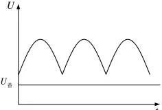
895 the maximum extent. In order to maximize the energy utilization ratio, the dc voltage value with the hysteresis control method is judged whether the output voltage less than a fixed value. When the thermoacoustic generator is in low output condition, thermoacoustic power generation device can output a certain electric energy. This power is design basis. The electric energy is stored in the inductance with the hysteresis control method. The battery will be charged when the voltage value is equal to rated value of the battery. This electric energy is stored and used. The basic working principle is shown.
U蓄
t U
A) Output Voltage Is Higher Than Rated Voltage
U蓄
t U
B) Output Voltage Is Lower Than Rated Voltage
U蓄
t U
[image:3.612.316.529.75.253.2]C) Between The Former And The Latter Fig 1 Comparison Between Output Of The Generator
And Terminal Voltage Of Battery
Fig 2 Storage Energy Device Circuit Structure
ac
U
—the output alternating current of thethermal acoustic power system;
R
e internalresistance;
L
e —inductance;U
dc —rectified voltage;C
—capacitance;L
—energy storage element;D
—diode;E
—the battery;R
—the battery internal resistance;U
g—the MOSFET grid drive signal;The hysteresis control is a kind of feedback control technology [17]. Here the voltage hysteresis control, can make the output voltage wave always follow the tracks of the given reference signal wave, the response speed is quickly. The error will be controlled in the need scope. The comparison signal of the reference voltage and the output voltage is sent to the hysteresis controller and the hysteresis controller will produce corresponding drive signal to control the switch of the MOSFET, such as on and off.
Control process as follows:
h
U
U
h
〈
−
dc〈
−
*1
=
g
U
The MOSFET isconduction;
* *
or
dc dc
U
−
U
〉
h
U
−
U
〈−
h
U
g=
0
TheMOSFET is turned off;
If the hysteresis controller output voltage value is higher than the set voltage, the MOSFET gate drive signal
U
g is high level, the MOSFET is the [image:3.612.136.254.251.331.2]896 inductance, the inductance can not store the electric energy. In the process of the MOSFET gate drive signal
U
g is high or low. This isdesigned for the inductance energy storage. When the inductance stores some electric energy and these are charged for the battery. According to the number of the energy storage of the inductance, whether or not for battery to be charged will be decided. The number of the electric energy storage of the inductance is not only related to the inductance value, but also the rated voltage. When the inductance of the storage battery power is higher than the rated voltage value, the diode is the conduction, the battery will be charged. When the inductance of the storage battery power is lower than the rated voltage value, the diode is not conduction, the battery will not be charged.
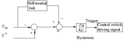
3.2 The Voltage Hysteresis Control Of The Differential Negative Feedback
Although the voltage hysteresis control can make the system a good dynamic performance, in the application, in the rising edge and falling edge nearby, in order to enable the output power quality signal appear to follow, overshoot or slow response, short wave oscillation phenomenon, and no real-time tracking the reference signal, the
[image:4.612.315.525.131.204.2]differential link is increased in the control. As shown in figure.
Fig. 3 Scheme of differential feedback control
3.3 The Parameter Design
The parameter design purpose is to design a reasonable battery rated voltage value and the inductance of the electric energy storage, in order to meet the voltage in the set scope of the hysteresis control, the voltage is stored by the inductance to realize storage electric power condition and reduce the freewheel diode reverse loss condition. This paper proposed the linear generator technical indicators and as is shown in table 1. According to the actual need, a 30 w permanent magnet linear generator is designed. The parameters of the prototype parts as follows:
Table1 Parameters Of The Permanent Magnet Linear Generator
Parameter Value/unit Parameter Value/unit
Rated power 30W Rotor outer diameter 44mm
Rated voltage 12V Rotor inner diameter 28mm
Phase 1 Axial length of rotor 30mm
Stator outer diameter 70mm Thickness of PM 4mm
Stator inner diameter 44.6mm Axial length of PM 15mm
Axial length of stator 15mm Air-gap 0.3mm
The designed steps are as follows :
1 The calculation of the battery rated value The linear generator nameplate data and the voltage value after rectifying are the reference base to calculate the rated value. This battery rated voltage value is 12v.
2 The calculation of the inductance value of the storage electric energy circuit
When the MOSFET is turned off, the discrete form of the inductance voltage equation is
on L L
t
I
L
U
10
1
−
=
(1)During the MOSFET conduction, the discrete form of the inductance voltage equation is
off L
off L L L
t
I
L
t
I
I
L
U
=
2−
1=
∆
897 During the MOSFET conduction, the inductance discharge and the battery is charged. The discrete form of the input circuit voltage equation is
R
I
E
t
I
I
L
U
Loff L L
L 2
1 2
2
=
+
−
=
(3)The MOSFET period
off on
t
t
T
=
+
(4)The MOSFET duty ratio
α
=
=
T
t
D
on (5)The discrete form expression of the inductance is
)
(
)
(
)
(
2 1
2 2 1
2 1
R
I
E
I
I
I
U
R
I
E
TU
L
L L
L L L
L L
+
+
−
+
=
(6)1
L
I
—From the initial time, the inductancecurrent after the MOSFET conduction;
I
L2 — When the MOSFET is turned off, the inductance current;U
L1 —From the initial time, the inductance voltage after the MOSFET conduction;U
L2—When the MOSFET is turnedoff, the inductance voltage;
t
on —The MOSFET conduction time;off
t
—The time of the MOSFET turned off;D
—The duty ratio;4.THE EXPERIMENTAL VERIFICATION
In order to verify the validity, with lower than battery rated value the battery is charged. According to the parameter value designed, the experimental circuit was made. The real picture is shown.
The output rated voltage of the electrical motor is 12 V and its current is 2A. The Hall sensor mainly detects the current flow through the conductor to measure the sizes of magnetic field generated around the conductor. The output voltage of the sensor keeps a linear relation with the size of magnetic field which has a linear relation with the current flow of the conductor. Therefore, the output voltage of sensor and the current have a direct linear relationship. In the experiment, the Hall sensor with the type of
[image:5.612.329.502.146.261.2]ACS712ELCTR-5B-T is utilized to detect the current with -5~5A input current and 0~5V output voltage.
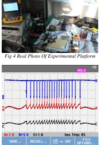
Fig 4 Real Photo Of Experimental Platform
Fig 5 Battery Charging Waveform For Half Wave Under The Differential Negative Feedback
From the diagram, when the voltage is low, the conduction will cost much time. With the rise of voltage, the time for conduction decreases gradually and time for pipe section (time for the follow current of inductance to charge battery) remains the same. In comparison with direct battery charge, the principle of charge circuit is shown in the following chart
According to the above diagram, the battery can be charged only when the output voltage becomes higher than the rating voltage. A:the simple sinusoidal alternating current
U
ac ;B :thecurrent for battery charge
i
.A : the output of Hall(7 legs of
[image:5.612.329.501.160.412.2]898
R Uac
+
-Udc
i
Fig6 Circuit Principle For The Battery Charged Directly
Fig7 Battery Charging Waveform For The Battery Charged Directly
From the diagram, when the voltage is low, the conduction will cost much time. With the rise of voltage, the time for conduction decreases gradually and time for pipe section (time for the follow current of inductance to charge battery) remains the same. In comparison with direct battery charge, the principle of charge circuit is shown in the following chart
According to the above diagram, the battery can be charged only when the output voltage becomes higher than the rating voltage. A : simple
sinusoidal alternating current
U
ac ;B: thecurrent for battery charge
i
5.CONCLUSION
In this paper, the way is proposed about permanent magnet linear generator output electric energy how to use efficiently for thermoacoustic power generation system. Through the voltage hysteretic control and
differential negative feedback method, when the thermoacoustic generator is low output condition, the output electric energyof thermoacoustic power generation device is well used. Such proposal
addresses the post treatment of instable electrical energy with variable amplitude and frequency converting generated by thermoacoustic power generation engine. Because of the limitation of time and conditions, the method still will be needed further improvement. In the later research, the mathematical algorithm should be applied to optimize the hysteresis controlling method, and combined with numerical analysis methods, with the method of programming to realize in the software, in order to achieve to track the input signal more accurately and fast.
REFRENCES:
[1]
YuGuo-Yao,LUOEr-Cang,ZHANGXiao-Dong,etal EXPERIMENTAL INVESTION ON
HIGHFREQUENCYTHERMOACOUSTIC-STIRLINGHEATENGINE[J],JournalofEngine ering Thermophysics2009,1,30(1):17-21 [2] ZHOUYuan,LUOErcang.Advanceinthermoaco
ustic technology[J].Journal of Mechanical Engineering, 2009,(45)3:14-27
[3] GAO Bo, LUO Er-Cang, CHEN Yan-Yan,
etal. THE WORK MECHANISM AND HEAT TRANSFERCHARACTERISTICINTHERMO ACOUSTICHEATEXCHANGER[J],Journalof EngineeringThermophysics,2010,2,31(2):324-326
[4] Yu Bo, Dai Wei, Luo Ercang, etal. High frequency standing-wave thermoacoustic engine with sinusoidal resonance tube[J] Cryogenics,2009(1):1-4
[5] GAO Bo, LUO Er-Cang, CHEN Yan-Yan, etal. Establishment and Simplify of the Weakly Nonlinear Thermoacoustic Model[J], Journal
of Engineering
Thermophysics,2011,8,32(8):1277-1282 [6] Zhang Limin, Wu Zhanghua, Luo Ercang,
etal.Acousticalpoweroutputcharacteristicsoftra velingwavethermoacousticenginesoperatingwit hfixedheatingtemperature[J],Cryogenics,2012( 1):7-12
[7] Zhang Limin Luo Ercang Wu Zhanghua Yu GuoyaoDaiWei,Thermalperformance
investigation on thermoacoustic double-acting electric generator with different working gases[J],Cryogenics,2012(4):8-12
[8] YU Guo-Yao, LUO Er-Cang, DAI Wei,
899 [9] Chen Mao, Ju Yonglin, Development of
Experimental Study on Traveling-wave Thermoacoustic Heat Engines[J],Journal of Refrigeration 2010,6,31(3): 21-29
[10]Wu Z H, Man M,LuoEC,etal.Experimental investigation of a 500 W traveling-wave thermoacousticelectricitygenerator.[J],Chinese SciBull,2011,5,56(14):1088-1090
[11]LI Shan-Feng, WU Zhang-Hua, LUO Er-Cang,etal.INVESTIGATION OF THE MATCHING RELATIONSHIP BETWEEN A TRAVELLING-WAVE
THERMOACOUSTIC ENGINE AND REFRIGERATOR[J],Journal
ofEngineeringThermophysics,2009,11,30(11):1 818-1820
[12]MAN Man, WU Zhang-Hua, LUOEr-Cang, etal.ExperimentalStudyona400W Travelling-Wave Thermoacoustic Electricity Generator[J],JournalofEngineeringThermophys ics, 2011,4,32(4):557-560
[13]WU Zhang-Hua, LUO Er-Cang, LI Hai-Bing,etal.1kWSolar-PoweredTraveling-Wave Thermoacoustic Electricity Generation System[J],JournalofEngineeringThermophysics ,2012,1,33(1):19-22
[14]Tong Huan, Luo Ercang, Investigation on
ThermodynamicPerformanceofaDouble-
ActingTraveling-WaveThermoacousticHeatPump for High-Temperature Range[J],Journal of Refrigeration,2012,8,33(8):7-15
[15]Lin Xiaojian, Dai Wei, Zhang Limin Luo, etal.Traveling-wave thermoacoustic engine withendcouplingRCload[J],Cryogenics,2011,(3 ):11-15
[16]WANG Bo, QIU Li-Min, SUN Da-Ming,
etal.STUDY OF A THERMOACOUSTIC
ENGINE WITH CO2 AS WORKING
SUBSTANCE[J],JournalofEngineeringThermo physics,2009,9,31(9):1463-1466