Page AA
DIGITAL DATA CC»IMUNlCATIONS MESSAGE PROTOCOL (DDCl'lP)
ABSTRACT; The Digital Data ~ications Message Protocol (DDCMP) is a data link procedure that creates a reliable d.ata communication path between cODDllUnication d.evices connected. by da.ta links. DOCMP ensures the correct sequencing and i.ntegrity of d.ata transmitted over a data link. This standard. d.escribes the fUnctions, characteristics, interfaces, message formats, and operation of the DOCMP protocol. It is primarily intended. to assist the ind.ividual ilDplement.ing OOCMP. It le structured. to also provide general information describing the protocol to others who may need this level of irformation. It is not intended. to instruct those unfamiliar with the basic principles of data COIIIIIunications.
BCO.
31HfAR-78 Stu Wecker Carl Noeleke A
Size COde
"-.,
i
I
!
i
oec STD 121 POge AB
*Indicates th.at all pages of standard will always carry the sallie revision
"ILCOE I PAGE
NO. PAGE REVISIONS I NO. PAGE REVISIOI.3
---1---AA AS AC AD A, AF AG AH
"
AJ AK 1 2 3·
,
•
7 8•
"
11 12 13 14"
,.
17 18,.
SEC. RSV ·A A A 20 21 22 23 24 25 26 27 28 29"
31 32 33 34 35 36 37 38 39..
41 42 43..
"
..
47 48..
I SEC. I REV
··· ... ···_ .. _--_···-1 ... ··"' .. "' ..
=========== .. "' ... _-_ ... .STO I STO
DEC STD 121 pi'ge AC
·Indicatea that all pages gf stailOard will always carry the sallie revisign.
PAGE ! PAGE
NO. PAGE REVISIONS I NO. PAGE REVISIONS
---1---"
51 52 53 54 55 5657
"
59"
61 62 6J 64 6S"
6768
"
"
71 7273 74
""
76 7778 79 SEC. REV
"A A A A A
"
.,
I SEC. I REV
STD ! STD
REV A I REV
I DEC STD 121
~CMP Standa(c"d-'v"'."'.,'--_ _ _ _ _ _ _ _ _ _ _ _ _ _ -'P"'ag""-'AIlLP
DEC STANDARD 121
DIGITAL DATA COMMUNICATIONS !tESSAGE PROTOCOL
(DDCMP)
DDCMP COllllD.ittee: s. Wecker Chairman, Autho(
The Digital Data Communications Message p(otocol (DDCMP) is a data link procedure that creates a reliab!'e data comrr,unication path bet .... een communication devices connected by data links. DOCME' ensures the co(rect sequencing and integ(ity of data transmitted over a data link. This standard describes the functions, characteristics, l.nterfaces, ,!,essag€ fo(mats, ~nd ope(ac~on.of the DDCMP protocol. It is primarily l.ntended to ass 1st the 1ndlvidual implementing DOCMP. It is st(uctu(ed to also provide general info(mation desc(ibing the P(otocol to others who may need tnis level of info(mation. It is not intended to inst(uct those unfamiliar .... ith the basic p(inciples of data communications.
The information in this document is subject to change without notice and should not be construed as a commitment by Digital Equipment Corporation. Digital Equipment Co,!)oration assumes no responsibility for any errors that may appear in this document.
DEC STD 121 DDCMP Standard V4."
C.i'his ~'~andarj is written as a type II standards document. That 15, the document starts with the standardS sect10ns describing goals, motivations, scope, etc. followed b~' the t.echnical specification of the standard, I t is written so that the technical speclflcation can stand alone and be used for external (l.e. customer) dL;;t;ribution. Much of the information in the stanrlard sections 1S also Included 1n the technical spec1flcatlon to help motivate and instruct the reader of that stand alone document. In these cases, the standard section will refel: to the appropriate section(s) in the technical
~peciflcation pOl:t1on of the standard rather than repeat the
information.
The DDCMP p~otocol was designed to cl:eate an efficient mechanlsm for the error-free transmission of data over commun1cation links. Previous industry standard protocols were inefflclent in their use of full duplex channels and links with long delays (e,g. satellite). There was "1150 a requirement for a protocol that would operate on both synchronous and asynchronou,> Ilnks using existing DEC communications interfaces. No DEC or industry standard, at the time of the initial deSign (January 1973), met the requil."'mentf'
The operation of a communications protocol requlres that botn communication devices on che ends of the data link 1mplement the 1dentical message formats, operating rules, and error recovery procedures. When they are the sa;n~ implementation th1S is no problem, but wnen they are different lmple'Olentations, there must be a specification document that cl",arly and definitively desc;;ibes the protocol to which both implement~tionii> may refer. The DDCMP protocol is intended to be used tc connect both homogeneous and heterogeneous ccmp >t~ng systems. ThllS, there was a need to not only define the prot 01 but to create a precise wrl.tten specification of its def.nltion that could be uSEOd by lmplementors ln deSl.gn1ng and implementing protocol modules.
The need to create a protocol whose requirements were not met by current stanoards, and the need to produce a written speclfication of that protocol were tne motlvations foc the creation of the DDCMP standard. Additional motivati'lg infor;nation can he found in tne technlcal speclflcation in sectlons 1.0 INTRODUCTION, and in 2.0 FUNCTIONAL DESCRIPTION.
Th~ goals of DDCMP sectl.on 2.3.1 Goals.
wEC STD 121
DDCMP Standard V4.0i Page AF
1.3 Non-Planned Effects Of Goals
There are no known non-planned effects of the nnCMP goals.
The follo<lHng goals cannot be met wi th the current structu'e of the nnCMP protocol:
1. To b-e efficient on channels with a very high error rate. On such .::hannels, forward error correction techniques may be mo'e applIcable and efficient.
2. To be opt.imal on channels with extremely ::'ow error rates. On these channels much of the protocol overhead may be
3. To be efficie;:t for messages with very shor.; data fields. In caSe5 "Ihen the transltlissions i'lre ext,emely short (1-10 bytes) other tecbniql~"'s may be more efficient.
4. Additional !lon-'3oals ar", in specIfication in section 2.3.2 Restrictions.
1.S Scope
DDCMP shall be implemented in ':t:('~e products being deVeloped that have all of the £ollcwing characterist...cs:
A link level protocol is reqUIred ') ensure data Integrity and se'"iuentiality.
2. Communications will be over common carrier facilities, or slmiliar local facilities, naving a significant probabll;~y of introduci;:g errors (relatiVe to the intended application). Communications will be to othpI Digital products non-Digital products implementing DDCMP.
4. The product will Implement the link level prCltocol in either s::.ftware, firmw<ire, cr a combInation of the two.
DDCM. o:ed not be implemented ",-hen any of the following applies: L II. llnk level protocol IS nct reqUIred to lnsure data
ggCBp Stapc'ud V4 a P 9" 'C
non-critical applications where the operation is monitored by an operator who can detect and manually correct errors (e.g. a Teletype compatible terminal operated in echople .. lIode). The communications facilities have an insignificant error rate (relative to the intended application). This lII.I1y be due to their inherent design or due to the use of com.on carrier pro·,dded error correction facilicics.
Communications will be to non-Digital products which do not implellent DDCMP.
4. The product will implement a link level protocol in hardware ratheJ: than in software and/or fir_are. An example would be a parallel, error-controlled, local bus.
1.6 History of previous Standardization Efforts
DDCMP was designed to overcome the inefficiencies inherent in previous generation protocols such as Bisync. These character-oriented protocols had a number of deficiencies including (l) no error cheek on control information, (2) two-way alternate operation, (3) rigid structuJ:e, and (4) interllliJ:ed device, lJ.essa.ge, and link control. DDCMP was built on the experience gained with the PDP-Iii protocol DECsync. It was sillliliar in design but used a less powerful erJ:or detection scneas and only operated in full duplex point-to-point mode. DDCMi' was designed at the Sdllle time as IBM's SOLe and ANSI's ADCCP _re evolving, and used SOIlle of the ideas generated in those designs. On January 12, 1973 Digital chartered a co_ittee to define a standard protocol for intercolllputeJ: message cOllllllunication. The cOllDlittee consisted of: Stuart Wecker, Rand D, Chairman: Stephen RUssell, PDP-Iii Commun1cationsf and G~orge Friend, DECcOIIm Marketing. The resulting effort froll the initial design was DDCMP version 1.I!!, February 1973. Since that tiae there have been a nUlllber of revisions and enhancements to the protocol to bring it up to its present version •• I!!, December 1977 level. The interlllediate versi.)Us and personnel involved were:
1. Initial design 1.11 -February 1973. S. Wecker, S. Russell, 0. Friend Review 1.tI - April 1973
DEC STD 121
ppCMP standard y4 " Page AH
Redesign 2.0 -June 1973 S. Wecker, H. Schlesinger Review 2.1 - November 1973
S. Wecker, S. Russell, J. Holmes, H. Schlesinger, B. Paulson, A. Kent, A. McCutCJlen, J. Sauter 5. Review 3.0 - March 1974
S. Wecker, J. Bolmes, A. McCutchen, C. Cannizzaro, H. Schlesinger, W. SrOka, J. Gilbert
Changes to 3.0 - July 1975
All of the above plus DDCMP development personnel 7. Review of changes 3.02 -August 1975
S. Weckel:, J. Holmes, H. Schlesinger, J. Gilbert, G. Friend, S. Russell, A. Kent, D. McClure
B. Changes and document revision 3.03 - December 1975 A • .tent, S. Russell, T. Lauck, H. Schlesinger, S. Changes and complete rewrite 4.1'1 -December 1977 S. Wecker, T. Lauck, A. Kent, H. Schlesl.nger, B. ROsenbaum, B. Collins, L. Dimino, G. Conant, G. Larson, R. Lisee, D. McClure
Version 3.1'1 was approved as a nEC standard in May 1974 with the recommendation that a more complete document be produced. tlo document was submitted to standards between that initial approval and thlS SUbmission of version 4.1'1 of March 1978. The list of changes from the last approved verSl0n 3.1'1 to the current specification is included in Appendix F of the technical specification. Prior changes {from 1.0 to 3.0) are not incl>.lded in this document as they occurred prior to stan>iardization.
1.7 Related Cur rent Standards
DDCMP 1.S a physlcal link protocol ensuring reliable communications on a data link. Other protocol st~ndards with simillar goals and functionality are ANSI: ADCCP, ISO: HDLC, and 10M: SOLC.
DEC STe 121 REV. A
PpCHP Standard VI II P gq .. I
PPCIIP only operates at the physical link level. When PPCMP is used as a component in distributed computer networks, host front-end processors, remote terminal concentrators, and rellote entry/exit systems, higher level protocols must be used on top of PDCMP to perform functions such as routing, device control, link multiplezing, flow control, and error recording. In PRCnet the next higher level protocol, the network level protocol, is the Network Services Protocol (NSP). A silliliar industry standard protocol is the CCITT X.25 protocol.
In PDCMP maintenance lIIode a higher level protocol is used to perform the actual maint.enance fUnctions of down-linE: loading, dumping, and link testinq. The protocol that performs these functions is the Maintenance Cpe~atlOn Protocol (MOP).
1.8 Future StandardS Activities
A number of. ptoposals have been !Dade during the design of DDCMP that wete deellled beyond the scope of the ptesent wotk. They should be consideted in the futute if enhancements to ODCMP are consideted. These are:
1. Addition of a single lBes~'lge NAlt. This would cause tettanstr.ission of a sinqle message without having to go back and retransmit all mess.:.y:es after the messaqe in etror. 2. Add a window aize to STRT and STACK messages to specify the
maximum numbet of lIIessaqes the other station should send before waitinq for acknowledqment. A zero value would mean an unlimited number (up to 255) /lay be sent. A small value would solve the ptoblem of syst~ms with small buffet capacities sending HAlts and causinq tetransmissions and extra overhead due to a lack of buffet space.
3. Add a mazimum message size in the startup sequence. Add a HAK teason-lBessage type not supported-to leave protocol open ended for future extensions.
Add a MODE message to specify the operating options such precede all message~ with sync sequences, use single message NAlt, mazimum message size, lenqth of sync sequence, type of station, t.ype of link.
Po not require explicit REP messages to be sent by stations t.lat transmit only aftet being selected (half-duplex a:ld mult.ipoint tributaty stations) since the pipeline is emptied after every select lind retransmission is implied. In these cases duplicate received messages should be ACKed. 7. Add a shutdown (hangup) sequence when ttansllli.<JIsions are
Page AJ
B. Stud}' appllcabillty bit-oriented
commu .lcations hardware.
1.9 Known Incompatibilities with Current Softwar~
Products releaded prlor to January 1, 197B, wic.h the e>lCeptlon of tIle DltCll, implemented version 3.11 of DDCMP or lll'.plemented some subset of the changes to DDCMP from VerSlon 3.0 to Verslon 4.". Due to cn", lack of documented conformance testing it is unknown whether or not any of these products conform to DDCMP Version 4.11. 'rhe products of primary concern in this area ace:
1. OECNET-llM/S V1.~, '11.1, V1.2 2. DECJiI£T-110 v1.a
3. DECNET-IAS Vl.Il OAS-80 SERIES
DECNET-IIM/S/D and lAS will be re-released in Q3, FY7S at Vecslon 2.11. These products 101111 confocm to DOC;~P V4.iI.
Terminology speclfic to this standacd can be found either defined where appropriate 1n tne technical speclflcatlon or ln Appendlx A Glossary in the technical speciftcation.
Conformance is demonstrated by showing that a new implementatlon lnteroperates acceptably with itself, with all applicable pr.;vlous Digital lmpleJlentatlons, and (if full duplex point-to-polnt 1S
~mplemented) in loopback mode. For each pcevious implementation.
DEC STD 121
DDCMP St"no<lrd V4.0 Page AK
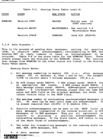
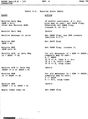
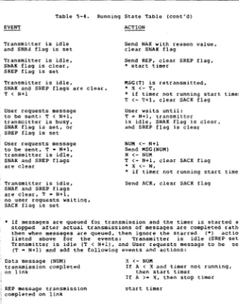
DDCMP Spec/4.11 -121 PEV. A
DECNET
DIGITAL NETWORK ARCHITECTURE
Dic;lit.a1 Dat.a COllllllunicat.ions Messllc;le Prot.ocol
Specificat.ion
Version 4.8
1-Marcb-1978
DIGITAL EQUIPMENT CORPORATION MAYNARD, MASSACHUSETTS 1111754
I
DDCMP Spec/4.8 - 121I·· .. '·'"
Page 2I
1 This material lII.!Iy be copiea, in whole or in part, proviaea t.hat the : above copyright notice is incluaea in each copy along with an ! acknowledgment that t.he ..:opy aescribes t.he DDCMP protocol developea by : Digit2.! Equipment. Corpoation.
I
This lIUlt.erial may be cbanged witbout notice by Digital Equipmenti
;~~~~:~~~n';hi~~dll~~g!:;a~~!~~: Corporation is not responsible for,
I DDCMP Spec/4,1iI -121
I March I, 197B
Page ~
The Digital Data Communications Message l'rotocol (DDCMP) provides a data link control procedure that ensures a reliable data communication p.1th bet·~een communication devices connected by data links. DDCMP has been deiligned to operate over full- and half-duplex synchronous an~
i asynchronous channelS in both point-to-point and multipoint modes. It
i can be used in a variety of applications such as distributed computer networks, host front-end processors, remote terminal concentrators, and remote job entry-exit systems.
, This document describes the functions, characteristics, capabilities, and operation of DDCMP. It is primarily intended to assist the I individual implementing DDCMP within a system. It is structured, however. to also provide general information descr iIJing the protocol for others who may need this level of information. It is not intended to instruct those unfamiliar with the principles of data , communications.
i DDCMP Spec/4.1 - 121
I Much I, 1978
: 1.1
!
2.'
i 2.1
: 2.2 2.3
2.'
,2.5
i
3.113.1 3.2
...
4.1'.2
'.3
...
5.'
5.1 1~:i
i 5.4 i 6.1'6.1 6.2 : 6.3
Table of Contents
FUNCTIONAL DESCRIPTION Relationship to DECnet FeatuJ::es
OpeJ::ating RequiJ::elDents Data Link Functions Functional OJ::ganization IN"l'ERFACES User Interface Device Driver Interface
MESSAGE FORMATS
Notation Data Me&Sagf"!S Control Messages Maintenance I!'essages OPERATION Framing Link ManageJDent Message Exchange Maintenance Mode ERROR RECORDING Tbreshold :=ounters CUlllulative Counters Background Counters
Page 4
I
APPENDIX A GlossaryAPPEMDIX B Formal Syntax Definition I APPENDIX C DOCK!' Block Check C01Dputation
i
APPENDIX D Format SWlllllaryI
I
APPENDIX E EZaJIlples APPENDIX F Revision HistoryI
List of Tables
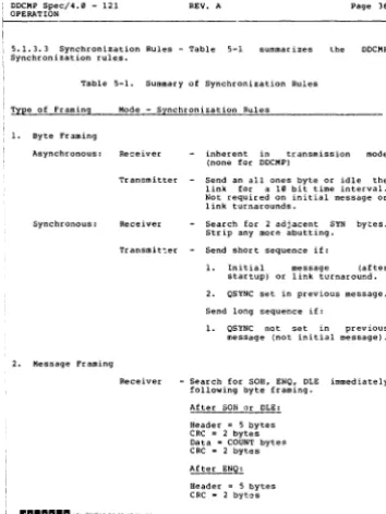
5-1 Su_ary of Synchronization Rules
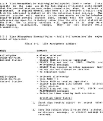
, 5-2 Link Manaqeaent SUllllllary
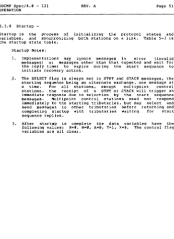
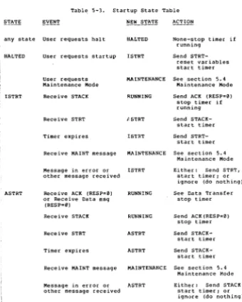
i 5-3 Startup Stat.e Table I 5-4 RUnning State Table
Maintenance State TaDle
63 65
..
78
,.
41DDCMP Spec/4.0 - 121 Page 6 IN'!'RODUC'!'_-"'"ON'---_ _ _ ~
In the design of computer communications networks, one of the b<lsic consl.derations is the physical transmissl.on of data from one computer to another over a physical data channel. In the absence of transr.lission errors, this task becomes relatively slm9le. Once errors are introDuced, however, data sequencIng and synchronl:l:atlon pr"blems occur between the transm1tter and receiver. The solutlon to these probh,ms consists of a data link control procedure or commun1cat1ons protocol that ",nsures the correct sequenc1ng and integrlty of data transmittec. between computers over a data link.
Dig1tal Equipment Corporation recogni:;!:ed the need for such ;'I
DDCMP Spec/4.0 - 121 FUNCTIONAL DESCRIPTION
Page 7
The Digital Data Communications MeSsage Protocol (DDCMP) has been
design~d for use over commUniCaLOn cha .. nels to provide data
integr i ty, message sequencing, and management of the physIcal char.nel. The protocol defines the structure, content, and sequencing procedures for the transmission of data between computers and the techniques used for error detection and recovery. DDCHP tcesIdes at a level above the communication medium (i.e., the physical transmission of bits over the communication channel). DDCHP is concerned with the logical transmission of data grouped into physical blocks known as data messages. The primary function of the protocol is to exchange these d"t" mess"ges while ensuring their correct sequencing and integrity when s"nt over communication channels.
Computers adhering to the protocol will be able to correctly exchange data (between their respective address spaces) over a link. It is the level above the protocol that is concerned with the meaning and understanding of this data once correctly exc~.anged. With remote entry stations and concentratc;,cs, this inc.ludes device addressing, device control, and data formatting. With computer nelworks, It includes problems of network routing, process sync~ronization, link multiplexing, flow control, and network management.
Programs wishing to communicate ",sing DDCMP must agree on the syntax and semantics of the data transmitted within the DDC!'!.P envelope. DDCMP may thus be viewed as a black box creating an error-free sequential communication path over which data may be transmitted. On multipoint linkS, DDCMP creates multiple sequential data paths between the (:ontrol station and the multiple tributaries on the link. I f the physical channel conn-,cting two computers is truly error-free, much of DOCHI' is not necessary.
2.1 Relationship To DECnet
DECnet is a family of hardware and software products that create distributed networks from DIGITAL computers and their lnterconnecting data links. DECnet creates a general mech"nism for sharing resources and prOVIding interprogram communications within a distributed data processing environment. DECnet implementations adhere to a common network architecture that defines the structure and protocols each must use to communicate through the network. ,'he DIGITAL Network Architecture (DNA) defines thIS common structclre.
DNA provides a modular design for DECnet. Its functional components are defIned within three dh:tinct layers,
DDCMP Spec/4.i1 -121
I FUNCTIONAL OESCRIPTION
Page 8
channels).
3. The Application Layer {whiCh supports user services and programs and provides 1/0 device and file access).
I
i:~~k DD~~~ti~~to~~e~re!~~~i~nd t~~PP~~~~e~he A~~~~~!~~~[~~ th~hi:hY~!~:~
provides control oyer the physical link operation and ensures bothI data integrity and the sequentiality of data transmitted over a single
! phY!'ical link. It should be noted that DECnet lS not a part of the DDCMP standard specification and that IlIlCMP lIIay be used, independently, in a wide variety of systems and environments where erro(-free communication is desired.
2.2 Features
I DIlCMP includes the following features:
1. Error detection using the 16-blt, CRC-16, cyclic redundancy check error detection polynomial.
2. Error correction by letransmission.
J. Message seguencing, which permits up to 255 outstanding messages for pipelining.
4. Operation that is independent of the channel bit width {serial or parallel) and transmission characteristics {asynchronous and synchronous}. DDCMP will operate ~ith a wide variety of communication hardware {e.g., character interrupt a:-:,1 block transfer or DHA) and modems. 5. COJ!llllon operation over full- ana half-duplex, point-to-point
and multipoint channels.
6. A positive startur: procedure that synchronizes both ends of the link.
7. Si/nplicity and efficiency with only a few message formats. A maintenance 1II0de for diagnostic testing and bootstrapping functions.
i DDCMP Spec/4.i1 - 121 ~FUNCTIONAL DESCRIPTION
REV. A Paqe 9
!
2.3 Operating Requirements
! DDCHP was designed to serve the needs of interprocessor cODllllunicat.ions in a wide variet.y of applications and envirolUllents. DDCMP will , provide=
1. High Performance. DDCMP will provide hiqh data throuqhput on links capable of such and make optimum use of link characteristics.
wide Applicability. DDCMP will ensure operation that is independent of channel type over a wide range of system configurations.
3. Use of Available Hardware. DDCMP will he able to operat.e with most CODllllunicat.ions equipment that is utilized with minicomput.ers.
2.3.1 Goals - In addition t.o ensurinq the error-free transmission of data, DDCMP was desiqned to lIIeet specific perforlllance and compatibility requirelllents. These goals are;
1. Create a protocol for the transmission of data over communication links to provide the correct sequencin'l and integrit.y of tbe data transmitted (even when the link lIIal distort the information translllitted).
2. Operate ov"!r a wide variety of cOllllllunications devices available on llticro, lIIini, and lIIaxi computers in bit seria" (asynchronous and synchronous) and bit-parallel modes. Operate over point-to-point and lIIultipoint circuits in both ful1- and half-duplex lIIodes using a common set of lIIessages and operating procedure' .•
Provide for the efficient transmission of binary (transpar;entl data.
Ensur;e both high performance and simultaneous operation over full-duplex channels where long circuit delays may be
encountered. '
6. Provide error r;ecording and reporting features so that a degraded link can be detected and repaired pr;ior to link failure.
DDCMP Spec/4. II - 121
FUNCTIONAL DESCRIPTION Page lil
Provide a basIc operational /hade for main!:enance functions such as bootstrappIng and diagnostIC testing.
Provide a rigid enough protocol so that all implementatior.s on the same channel type will operate together, independent of implementation techniques.
Create a protocol to minimize the memory requirement~, and execution time in the systems implementing the protocol. Create a protocol that allows the physical characteristics of the channel to become transparent to th'" user.
2.3.2 Restrictions - Even though DOCMP is a general purpose .linke protocol offering high pe~formance over a Wide range of applicatIons, there are a number of situati.ons in which it may not be optImal. Some of these re~trictions are:
1. DeCMP accepts data in bloc Its that are a multiple of 8-bit bytes. Within a data blvd:., a user C"ln interpret the data in any manner (i.e., 5-bit quar-tities), but the total block must be a multiple of 8 bits.
DOCMP may not be optimal when operating on links with long prop«gation delays and a high probability of error. Optimal technIques in these cases might include forward error correction and single message retransmission. When an error occu.s. DeCMP must go back. to the last sequential c:orrect message. thereby losing any pipelinlng in effect on the link. 3. DOCMP may not be suitable in some I'lultlpoint systems having many tributaries with low utilization and fast response requirements. Optimal techniques might include contention selection and broadcast. DDCMP uses a polling selection mechanism. which in some environments results in a longer response time.
On multipoint links, DDCMP supports only a single control station. No messages can be exchanged directly between tributaries. Within a given system, the control station can not float among the tributaries.
DDCMP Spec/4.8 - 121 FUNCTIOnAL DESCR'tPTION
2.4 Dat.a Link Funct.ions
Page 11
The DDCMP prot.ocol is an ext.ension of t.he dat.a communicat.ions link, providing a nWllber of fUnct.ions t.o t.he user of t.he prot.ocol. DDCMP may be viewed as a black box creat.ing an err.:Jr-free sequent.ial managed dat.a link. On t.he t.ransmit. side. lIIessages are given t.o DOCMP, which delivers t.hem over t.he link and not.ifies the user when t.he delivery has successfully occurred. On t.he receive side. the user provides buffers that are filled wit.h correctly received messages by DCCMP. The t.erm ·user- refels to the process or program exchanging messages with t.he protocol. In DECnet it. might. be the next. higher level protocol (i.e.. the Network Services Prot.ocol). In other syst.ems or struct.ures it. lIIight. be a service process or t.he end-user direct.ly. DDCMP eJ:t.ends t.he capabilities of a data 1 ink to include the following features:
1. Creates an error-free data path. DDCMP t.ransfers data between protocol users over a physical link, while maintaining data integrity within some very small undetected error probability. If data integrity cannot be maintained, no data will be transferred.
Transfers mes~aqes in proper sequence. Messages will be delivered from one user to the other in the same order as they are sent. even though DDCMP may require the use of retransmission or other error recovery techniques. 3. Manages the characterist cs of the channel. If the channel
requires receiver addressing- and/or arbitration of transmission requests. DDCMP is responsible for that management.
4. Interface t.o lIIoder control signals. DDCr'lP must interface with signals necessary for the opera'(ion of t.he physical channel, (e.g., modem control signals not handled by other components in the system). It. lIIay do this directly. leave i t up to the hardware device driver, or let the user of t.he modem control code control these signals through the prot.ocol interface.
5. Accesses data in blockS cor.sisting of byt.e quantities. ODCMP accept.s data in blocks consisting of a-bit byt.es. All 256 8-bit combinationE' are transmit.table, and transparent. to DDCMP. The protocol will allOW blockS of up to 16,383 bytes to be transmitted. However. the CRC-16 error detect.ion polyno.ial used is lIIost effective with blockS up to 4893 bytes long.
6. Provides restart or initialization notification. If the other end of th.., link reso!ts or initializes. DOCMP will notify the user.
IJIJCMP Spec/4.11 - 121
FUNCTIONAL DESCRIPTION Page 12
7. Provides start and stop control. The user controls the protocol and can start (or relnltialize), and stop (or h;.lt) the operation of IJIJCMP.
a. Provides notification of channel error. When a persistent error is detected, the user is notified of such a condition. Such errors might be (a) too high a bit error rate; (b) outages; (e) noneJastent eommunications1 or (d) modem failure.
9. Provides a maintenance mode. IJDCMP creates a data envelope with bit error-detect ion-only capability for use diagnostic testing and system bootstrapping functions.
Functional Organization
From an operational viewpoint, IJDCMP consists of three functional components: (1) Framing, (2) Link. Management, and (3) Message I::xchange. The following sections provide a generic model describing each of these components. This model IS he'.pful in understanding ODCMP operation. It is providea as an aid in implementation design (by enabling an indivi"'::ual to understand the protocol, its operational intentions and motivations). It is not intended to describe specific operating detai~ s of ODCMP or subsets of OOCMP. For specific information on the actual protocol operation refer to Section 5.11.
2.5.1 Framing Component -Framing is the process of locatIng the begInning and end of a message, at the receiving end of a llnk. Synchronization is the process of locating some ent1ty (e.g., a bit or byte) and then staying in step or operating at the same rate as that entity. SynchronizatIon of data on a IHlk must occur at the bIt, byte, and message levels before framing can be accomplished. The following paragraphs describe how DOCMP provides synchronization at these levels:
1. Bit synchronization. Locat1ng a bit on the link. This function is accomplished by the modems or interfaces on the link and is not a part of IJIJCMP.
DDCMP Spec/4.B - 121 FUNCTIONAL DESCRIPTION
Page 13
raw, and then counting every 8 bits as a byte. The unique pattern is such that any skewing to the eight or left will not prC'duce a sequence match. On 8-bit or 8-bit multiple parallel links, byte synchronization is inherent in the link. For other types of links, techniques will have to be desi'lned to locate the proper 8-bit byte window.
3. Message synchror.ization. Locating the first byte of a message. In DDCMP, this is done by searching for C<'1e of three special starting by..:es after achieving byte synchronization. Once one is found, simple rules will Locate the end of the message. The message is framed and ~ay be pt"ocessed. The starting byte also defines the format type of the message and how the remaining bytes are :0 be interpreted.
The byte and message synchronization techniques wet"e chasen to allow the greatest flexibility an!" independence from the actual dJ.ta lir_k characteristics. By using these techniques, D[lCMP can opet"ate an serial synchronous linkS with typical charact<lr interrupt or black transfer devices and an serial asynchronous linkS using 8-bi~ bytes. Byte synchronization is specified in DDCMP and is sppcific for each data link and its characteristics. Message synchronization is the for all link types once byte syncht"onization has been established.
2.5.2 Link Management Component - The Link Management Component t"esolves the transmission and recepticn on link'! that are ';onnected to twa or more transmitters and/or receivet"s in "- given direc~ion. This is tl:ue of half-duplelC and multipoint cr.mnels. Lir,k management occurs for both the transmitting and receiving functions. On half-duple:.!: links, one station must be recelving whU" the othel: is transmitting. The switching bet ... een transmit and H'~eive is via a selection fl~g. The station that io; tl:ansmitting ends transmission by setting the fiaq in its last message. This signals the receiver to complete reception of this message and then enter transrlit mode. For reception on multipoint links, the link appears as 1 party line. One station is designated t:he control station, ':ne others are tl:ibutaries. All messages contain a tl:ibutary addrf'ss to identify them. Messages to a tributary are received by a·,c tributarles and ignored by all except the one with the matching acdress. Messages from tributaries are ignored by other ttibutaru~s a---.d received by the control station that verifies the tributary :lddres!' to be the one selected. Message traffic is only between the control station and tr ibutar ies.
For transmission on multipoint linkS. the control ;tation manages the link and assigns translr.ission ownership or SElection to tributary stati'Jns via a selection flag. Tributary station-" once selected, may
DDCMP Spec/4.1!1 - 121 Page 14 FUNCTIONAL DESCRIPTIO"'N _ _ _ _ _ _ _ _ _ _ _ _ _ _ _ _
to the control station in the last message of a transmission sequence. Timers are used by half-duplex or control stations to hltndle the caSe of a lost flag (i.e., the me'Ssage containing the flag is in O!rror). A ti.er is started when waiting for the next message. If it expires it is assumed the selection flag was received in enor and the station operates as if it received a valid selection flag.
2.5.3 Messag2 Exchange Component - The message exchange component is the part of OOCMP that creates the sequent;~l error-frf!e link. This component transfers the data conectly and in sequence over a link that has some probability of introdUcing errors. Once framing is accomplished, this component operates at the message level, exchanging data and control messages. DDCMP is a positive acknowledgment retransmission protocol. For each data message correctly received and passed to the user, a positive acknowledgment is returned on the link notifying the transmitter of th, correct receipt of the data message. If incorrectly received, the data message is not passed to the user and not acknowledged. Eventually, it will be retransmitted. DDCMP uses the CRC-16 cyclic redundancy check for error detection. This section describes the component parts of the message exchange mechanism along with their des;]n characteristics and functions. The basic positive acknowledgment ll'.essage exchange component requires the following:
1. a data message with message number n:
2. a positive acknuwledg_ent with lllessage nWllber n lACK): 3. a timer.
It operates in the following manner:
1. The transmitter puts the next message number n in the data message, adds the CRC block check to the message, puts it in the required framing envelope, and sends it. When it has been transmitted on the link, a timer is started. 2. The receiver frallles and receives the message, checks the CRe
for errors, and comparE.s the message nlalber with th~ next. expected. If the number is correct, the receiver returns a positive acknowledgllent lACK) with that number. passes the lIessage to the receiving user, ana increments the next expected nulllber to n+l (lIIOdulo 256). I f the number is in er[or, the message is ignored.
3. The transmitter follows one of two procedures:
It receives a positive acknowledgment and compares the number received with the one expected. If it agrees, the
transmitting user of successful receipt, stops the timer, and increments the next message number to n+l (modulo 256). If the acknowledgment does not agree with the e:tpected number i t is ignored.
It receives nothing and the timer expires. translllitter initiates error recovery. Various eeror recovery options are available. The ones used in OOCMP are presented below.
I
~e ~i~~~b~~a~~e (:~~~~~~i~~~h~~9~t~~~P~~:~10~s (~:r~~~~l;~~. s~:~t~~~
thf' controlling station must wait until a tributary or the other ,station is selected and transmits before it determines that a message : or ACK was not properly recel.ved. This lfIakes the timing independentof the selection of stations.
This mechanism is adequate for creating a message exchange compo:"ent. The following additional messages and operational techniques of DDCMP : are used to achieve higher performance (via pipe1ining) and faster : error recovery (via error notification) but do not add to the basic
integrity of the data transfer mechanisms.
1. Negative Acknowledgment (NAK). Tt:e time-out value (used t'J detect an error when an ACK is not returned) lIIust be long enough to account for delays such as propagation, line turnaround, local processing of the data message, and the generation of the JI.CK. Tillle-out va~ues might be a few seconds while the actual delay may be on the order of a few milliseconds. If the only way to determine an error is to wait for a time-out, undue waste and inefficiency are encountered. A negative acknowledgment provides a means for more immediate notification of some error conditions. If the receiver does not receive the message correctly, i t sends a NAK, whl.ch triggers the retransmission long before the timer eJ:pires.
In DDCMP, NAKs are sent in response to cyclic redundancy check eerors, but not to wron£, message numbers. If the receiver gets a message with the wrong number, the message is ignored and the time-out condition triggers the transmitter to retransmit. If NAKs were sent in both cases, long delays could occur under certain timing conditions.
2. Reply to Message Number (REP). When the tilDer expires, it LS unclear Whether the message was received in error or the returned ACR was in err.or and not received properly. (ACKs also have CRC checkE on them). In this case, rather than retransmit perhaps a long message, a REP is sent with the message number of the message previously sent. If the message with that nUlDber was received correctly th~' response to the REP is an ACR, otherWl .. e it is a filAR. The REP forces the transmitter and receiver to synchroni~e their J:umbering
DDCMP Spec/4.1 - 121 PUNCTIONAL DESCRIPTION
is restarted after !lending a REP. If it expires again the process is repeated. After some specified number of these time-outs. the transmitter will notify the DDCMP user, who may declare the link out-of-service.
3. Pipelining. 'l11e ability to send more than one message without waiting for ACKs to each Sl!ccessive message is called pipelining. W:thin DDCMP, messages are numbered from 1 to 255. This numbering is cyclic (module 256) in that after messao;e number 255 tbe next message number is I. ACKs .Iot only confirm that the specified message nuaber has been received correctly, but that all previous lIessages with numbers between the one acknowledged in the last ACK and the one acknowledged by the current ACK (modulo 256) have been received correctly. If an ACK aessage is in error, the information lost is automatically inclUded in subsequent ACKs. eliminating the sending of REP messages i f the ACKs are received prior to the expiration of the transmission timer. This technique is 31so used with the REP message, the nUlabe[ sent in the REP being the nUlllber of tbe last message transmitted.
4. Piggybacking. The purpose of an Ar.K is to convey the message nUllbe[ of the last successfully received data message. If data message traffic is goin9 in both directions, the ACK number can be :<:ent piggybacked on or witbin the frame of the message going in the other direction. This technique saves separate framing ever head for the ACK.
5. ACI: implied in NAK. The nUliber refe[enced in a HAK reply identifies the last successfully received message as well as noting a received error. So NAil: implies that all messages prior to the one being negatively acknowledged were received correctly.
6. Initialization. The method of setting message nUlllbers to initial values is called initialization. It is accomplished by STRT and STACK messages that [eset message numbers to zero. It is used initially or afte[ a failure to reset nUlllber values at both ends. It is designed so that one end cannot be initialized without the other.
I DOCMP Spec/4." - 121 , INTERI"ACES
,3.0 INTERFACES
Page 17
I This section descr ibes how DDCMP is viewed by a user of the protocol , and how the physical interface device or driver is vl.ewed by DOCMP. A gener ie descr iption of the information that must be passed across the interfaces to the user and the device is presented as an aid for implementation design.
,3.1 User Interface
: The interface between DDCHl' and the user consists of a number of commands to DDCHP and responses from DDCMl'. In these commands and responses, the user exchanges data and control information wl.th the protocol. The actual l.nterface mechani!'<m depends heavily on the features and cap .. bilities within the operating systems running DOCMl'. Mechanisms for exchanging this information might include shared tables, calls with parameter lists, I/O registers, and interrupt mechanisms.
I Three kinds of information are exchanged in thE command/response sequences: (I) data, (2) control information, and (3) error information. Data is the user information to be sent or received by the protocol. Its description usually consists of a starting buffer address and a lew;th or character count, or a chain of addresses and counts. Control is information to start and stop the protocol and notify the user of protocol l.nitl.alization. Error l.nformation is provided by the protocol for use in determining the physical condltl.on of the link and when maintenance is necessary. OOCMP is totally controlled by the user of the protocol. It is only activated by a command request from the user and continues to operate even when large numbers of data errors occur on the physical link. It is started, stopped, and reinitl.ali:;:ed only upon commands from the user. On multipoint. links, independent cO'llllland and response sequences are maintained between the control statlon and each tributary on the link. The link appears as multiple point-to-point links, one for each tr ibutary address.
i DDCMP Spec/4.1J - 121 INTERFACES
3.1.1 COllllllands To DDCMP - The basic cOlll1ll.ands tc DDCMP are: Page 18
1. Initialize Link. Initialize the protocol ana start the data link.
2. Stop Lir.k. Halt the protocol. In some dial-up situations, a method lIIay be employed to force the IDOdelII to hang-up. 3. Transmit Message. Give a message to IlDCMP for transmission.
As an option the user may specify t.hat it wishes t.o send the lIIessage within t.he maintenance mode, or t.he protocol implementation may require a separate Maintenance Mode Initializat.ion cOlUland prior to a transmit. request. Receive Mes,iage. Give an ellPty buffer to DDCMP for reception of the ne}:t. sequential message. Alt.ernat.ively, the user might supply a pool of buffers t.o IlDCMP initially, and have t.he protocol select one. In this mode, t.here will be a co..and to return empty buff'!!rs to t.he pool so t.hey may again be used by DDCMP.
S. Ret.urn Transmit Buffers. This optional COlllllland. which can be employed after halting DDCMP, teturns outst.anding transmit buffers to t.be uset. The tesponse to this cOWlJDand would include whether they were already transmitted and acknowledged, not yet acknowledged, at not yet ttanslllitted. 6. Enter Maintenance Mode. This co_and is an option to first.
change to the .aintenance mode be fate transmit::ing or receiving maintenace IIIOde messages.
Responses Prom llllCMP - The responses frolll ~llCMP are:
1. Init.ialization on Other En1. The other end has testarted or initialized. This response will halt the protocol. The command to restart the protocol on this end will be an Initialize Link cOlllllland.
2. Initialization Complete. Response to Initialize Link command. This tesponse is optional. If it is omitted, the reply to a successfully received or t.tansmitted lIIessage will serve as initialization cOlllpletion notification. 3. Message Transmitted. Response to t.he Transmit Message
command. The lIIessage was successfully received on the other end (acknowledged).
4. Message Received. The next sequential lIIessage was successfully received. Either the user buffer specified in the Receive Message cOlDDland will be used, or a buffer will be taken from a pool, if such a buffering technique is employed.
OuCMP Spec/4.9 - 121
INTERFACES Page l~
Optionally. if the message w~s receH'ed in the maintenance mode it may be so marked, or a separate response may be first sent to the user to indicate that the other end is in malntenance mode. At that pOlnt, the protocol will halt. and the user will have to inltialize the protocol into the maintenance mode before receiving maintenance mode messages. 5. Translent Error Threshold Counter OverflOW. An error
threshold counter has overflowed. The protocol will continue operation. It must be halted by the ueer if the user wiShes to ceas", operation (refer to Sectlon 6.9. Error Recording). 6. Persistent Error. An error has occurred from which recovery
may not be pass :ble. Some implementations of the protocol may halt operatlon. SOIl',e errors that are classlfled as persistent errors in one system. might be tranSIent errors In another. The various types of errors are discussed leI Section 6.9.
Device Driver Interface
The interface between OOCMP and the line driver includes a number of commands and responses used to transmit and receive message blocks to and from the lInk, respectively. The actual interface depends heavily on the mechanisms and capabilities available in the I/O structure of the system within w'lich this interface operates. It also depends heavily on the split of protocol functions between DOCMP and the driver. The driver may be very protocol .ndependent aLd rely on heavy interactlOn with DDCMP for message framing, CRC calculation, ,md the syntactic and semantIc interpretation of message fields. Alterniltely. it <r,ay embody much of DDCMP including framlng. CRC checking, lInk manaqement, and link turnaround. In this mode, there would be less interaction with the semantic or message exchange portion of DDCMP. Consequently the drIver would handle many of the fUnctions related to link type and device characterIstics. The choice of driver capabilities and the split of functions depends on system characteristics, device req,Jirements, driver generality, and the interface to :It:-'er protocols. The interface described here lies between these two extremes and 's presented as an ald to understandlng what informatlon must pass across this Interface.
I ODCMP Spec/4.B - 121 INTERFACES
Page 20
3.2.1 Commands ToJ The Driver - The driver receives the fol101<ilng commands:
1. Link and Modem Control. These commands activate and connect a physical link to ODCMP. They also control the moJdem signals necessary for proper operation. These slgnals may be implicit in enabling the link (i.e., turn Data Terminal Ready (DTR) on) or explicit via modem control commands to allow DOCMP to directly control the modem. Typical commands ,.ight be:
Enable link. This commam1 connects the drlver to UDCMP and turns DTR on.
Disable link. This command disconnects the driver from ODCMP and turns DTR off.
2. Buffer Management. Received message blocks are pas;;ed to DOCMP via buffers. The buffers may be (a) individually given to the driver via Re.;eive commands or (b) initially allocilted to the driver 1n a Set buffers command or the Enable link command. In this second mode there must also be a commarj for DOCMP to return the buffers to the driver. On disconnection (Disable link command), the buffers must be returned to ODCMP or a buf~er pool.
3. Transmit a 810ck. This command passes a block to the driver for transm1ssion. The request mlght 1nclude one of the following options: (a) proceed with a synchronization sequence; (~) end with a pad; (cl calculate CRC; or (dl shutdown the transmitter after t1,e message. These ~ptions depend on the preclse d1v1sion of functions between the driver and protocol.
4. R£!ceive a Block. This command passes buffe.:s to the delver if 1ndividual explicit buffers are used. Otherwise, the driver might simply queue received blocks to DDCHP using buffers from a previously Obtained pool (as noted in 2). This command may also request the dr iver to resynchron1ze or reframe the receiver or there may be a separate Resync Receiver command.
nDCMF Spec/4.1 - 121 REV. A r Page 21
INTERF.~A:::C'::S _ _ _ _ _ _ _ _ _ _ _ _ _ _ _ _
-+ _ _
_
3.2.2 Responses From The Driver - The oriver issues the following responses:1. Moaem Status. The driver returns lIIodem signals, such as Data Set Ready (DSR), if appropriate to the interface. 2. Recejved Block. The oriver passes a receiveo oata block to
DOCMF. Depending on the functional split between the dtivet ana DDCMP, the dtiver lIIay calculate CRC (either in the drivet or device itself) ana pass this status with the block. When DDCMP is finished with the buffer i t returns it to the ativer via eith~r tal a Receive commano Of (b) a Retutn Buffer command. depenoing on the buffeting scheme useO. 3. TranSlllit Complete. The orivet will notify DDCMP when a
previous Tral'ulillit a Slack command has been cOlllpleteG.
ODCKP Spec/4.8 - 121 MESSAGE FORMATS
4.0 MESSAGE FORMATS
Page 22
This section df/'scribes the message formats of DDCMP. Data is exchanged over DDCMP links between the data source (master) and data sink (slave) within numbered data messages. Responses and control i."formation are returned from the slave to the master within unnumbered control messages. Stations contain both a master and slave. For the purpose of exchanging data, the station plays the role of master or slave depending on whether i t is transmitting or receiving the data. It is a distinction used for easy understanding and explanation of ODCMP. In reality, data is usually exchanged in both oirections. In the following explanation only a single direction is describeo.
Each oata message carr ies a number assur ing correct message sequencing at the Slave. The numbering begins with nUlllber one after initialiZation via the STR'r/STACII: control message sequence and is incremented by one (modulo 256) for each subsequent data lIIessage. Th~
Slave always acknowledges the correct receipt of data messages by returning the lllessage nUliber as a response either in the response field of nu'/!'bered oata messages going in the reverse direction. or. in an ACK unnumbereo control message. For efficiency, an a.::knowledgment of the data message with number n implies an acknowleOgment of all oata messages sent up to and including data message number n. Retransmission is used to recover from errors. The error recovery aechaniSIII uses tillleouts and HAK and REP control messages to resynchronize and cause retransmission if required. All messages also include station adoresses and link .-ontrol flags for use on multipoint and half-duplell: channels.
4.1 Notation
The following notation is used to describe the messages: Fielo (length) : coding = description of field Field - the name of the field being descr iced length· the length of the field as:
(I) a number meaning the numbet of B-bit bytes or (2) a number fOllowed by a B meaning the number of bits c:.oding = the representation type used:
B • Binary
BM ., bit map (each bit has independent meaning) C .. constant
Hull ., interpretation data dependent
Fields in separate messages that have the identical name are the field and have identical meaning.
DDCMP Spec/4.8 - 121 MSSSAGS FORMATS
Page 23
All numer ic values in tbis docwnent representation unless otberwise not.'d.
sbown in decimal
All beader ::ields and bytes of data are transmitted low-order or least-significant bit first on tbe data links unless otherwise specified.
4.2 Data Messages
Numbered data lllessages carry user data over DDCMP links. The forlllat of a numbered message is:
+---+---+---+----+---+----+---+----+---+ I SOHI COUNT! FLAGSl RESP INCMlADDRlBLKCKlIDATAIBLKCK2! +---+---+---+----+---+----+---+----+---+
SOH (1) = C - tbe nUlllbered data message identifier. value of 129 (octal -281).
COUNT(14B) : B • tbe byte count field. It specifies tbe nurr.~er of 8-bit bytes in the DATA field. The value zero is not allowed.
FLAGS (2BJ : 8M .. tbe link flags. Tbey are used to control link ownersbip and message synchronization. Tbese flags are:
bi t i l . quick sync flag (OSYNC flag). used to notify tbe receiver that tbe next lIless;;,ge will not abut tbis message and resynchroni:il:ation sbould follow this message. The quick sync flag reduces the length of sync sequences un syncbronous links.
I
DDCK' Spec/4.' - 121I
MESSAGE FORMATS: RESP(1)
: MUM(l) : B
-ADDR(l) ; B ..
BLKCKI (2) : B ..
DATA (COUNT) ..
REV. A Page H
COUN'l' and FLAGS forlll a 2-byte quantity. The first byte contains the 8 low-order bits of the COUll'l'. The second byte contains the 6 high-order hits of the COUN'i'. the SELECT flag the highest order or 1II0st significant bit of the byte. and the QSYNC flag the next bit in the byte.
lSIQtCOONTI high order bit
tran81litted last
low order bit transmitted fil:st the response nlllllber. It is used to acknowleoqe correctly received _ssages (the piggybacked ACKI. It is the nwnber of the last consecutive correctly received lDessage received from the addressed station by the station transmitting this message. It implies that all unacknowledged messages between the one acknowledged in the last RESP field teceived and the one acknowledged by tbis RESP field (modulo 2S6). have been teceived correctly.
the translllit nUlllbet. It is used to denote the nWlber of this data message.
the station address field. It is used to designate the address of tributary stations on lIIultipoint links. Stations on point-to-point links use the address value 1.
the block check on the nulllbeted lIIessage headet. It is cOlIIPuted on SOH through ADOR using the CRC-16 polynolllial (X~16+XAIS+X~2+l). BLXCKI is initialized to zero priot to computation and transmitted X~IS bit first. on teception the inclusion of BLKCKI in the computation will result in a zero remainder or
cae
if no errors exist. See Appendix C for a descr iption of CRe computation.the nUlllbered message data field. This field is totally transparent to the protocol and haS no restrictions on bit pattetns. groupings. or interpretations. The only requirement ia that i t contain the number of II-bit bytes specified in the COutrr field.
BLJ:CK2(2) : B - the block check on the data field. It is computed on the OATA field only using the polynomial and
DDCMP Spec/ •• ;' - 121 MESSAGE FORMATS
REV. A Page 25
4.3 Control Messages
Unnumbered control messages carry channel control inforlllation, transmission status, and initialization notification between the protocoJ. mOdules themselves. The individual fields are specific for each type of control III !ssage. Control lIIessages have the following general form:
+---+----+---+---+----+----+----+---+
~~~~!::~~~~~~::~~!:~~~!~:~~!~~~~!~~~~!~~~~~:!
where:
ENOCl) : C .. the unnumbered control message identifier. It has a value of 5 (octal - B85).
TYPE (1) : 8 = the control message type. This value denotes each control a:essage.
SUBTYPE (68) : 8 . the SUbtype or type mOdifier field. It provides additional informo!!tion for some message types. Its use is specific for each lIIessage type. FLAGS (29) : BM. the link flags. They are the saJlle as described
for numbered data messages (See Section 4.2). RCVR(l) : B = the control message receiver field. It is used to
pass information from the data message receiver or slave station to the data message sender or master station. Its use is specific for each control message type.
SNDR(l) : B .. the control ... essage sender field. It is used to pass information from the data message sender or master to the data message receiver or Slave. Its use is specific for each control message type. ADDRel) : B .,. the station address field. It is the same as
described for nl1lllbered data messages (See Section 4.21.
Page 26
NOT.
I The COllUllOn fields in data and control aessages are in the same
I position relative to the beginning of the lIIessage. The two types line up as follows:
+---+---+---+---+----+----+---+----+---+
150HI C 0 U N T !FLAG5IRESP I NUM!ADDR1BLKCK1!DATA!BLKCK2!
+---+---+---+---+---+----+----+---+----+---+
!ENQI'l'YPE !5UB'l'YPE!FLAG5!RCVR !5NDR!ADDRIBLXCK.3!
+---+---+---+---+---+----+----+---+
4.3.1 Acknowledge Message lACK) - The ACK lIessage is used acknowledge the correct receipt of nUlllbered data messages. It conveys the sallie information as the RE5P field in nUlibered lIIessages and is used when acknowledgments are I:equired. and when no nUlllbered messages are to be sent in the reverse direction. The forlll of the ACK message is:
+---+---+---+---+----+----+----+---_ .. _+ ! EIIO! ACKTYPE! ACKSUB ! FLAGS! RESP I FILL !ADDR! BLKCK) !
+---+---+---+---+----+---+----+---
+where:
ENO (11 : C = the cont-rol message identifier. , ACKTYPE(1) : C .. the ACK message type with a value of 1.
ACKSUB(6B) : C = the ACK subtype wit;h a value of 8. FLAGS (2B) : BM • the link flags.
RESP (1) the response number used to acknowledge correctly received messages. It is the same as described for nUllibered data messages (See Section 4.2). FILL(1) a fill byte with value B.
ADDRII) the stat.ion address field. BLKCX) (2) : B = the contra]. message hlock check.
i 4.3.2 Negative Acknowledge Message (NAIt) -The NAIt message is used to pass errOl: information from the slave f',r data receiver) to the master (or data sender). The error reason i.1 ~"cluded in the subtype field. The NAIt lIIessage also includes the same information as the ACK message. thus serving two functions: acknowledging previously received messages and notifying the master of some error condition. The form
I
DDCKP Spec/4. iii - 121i
MESS'G. FORMATSPage 27
i +---+---+---+---+----+----+----+---+
!
!~~~!~~~~:~~!~~~~!~~~!~~~!~:~~!~~~~!~~~:~:!
I
whel:e:, ENO(1) : C .. the contl:ol message identifiel:.
I
I NAKTYPE 11) the NAK message type with a value of 2. i REASONI6B) the NAil: el:l:OI: I:eason. Identifies the soul:ce
I:eason for the NAK.
i
1.El:l:ol: usually due to tl:anslllission mediulII: Value an-J Reason
1 ., header block check el:rOI: (data message BLKCKl 01: contl:ol message BLKCK3). 2 - data field block cbeck erl:ol: (data
_ssage BLXCX2). 3 -REP I:esponse.
2. El:l:or usually due to computel:/intel:face: Value. and Reason
8 ... buffel: telDpol:al:ily unavailable.
9 .. I:<!ceive ovel:l:un. 16 • message too long. 17 • message headel: format errol:. FLAGS (2B) = BM. the link flags.
i DDCMP Spec!4.11 -
121 REV. A Page 28 fSAGE FORMATS!
4.3.3 Reply To Message Ilum~er (REP) - The REP message is used to i request E:eceived message status from the slave or data receivel;. ItI
is usually sent wben the master haS transmitted data messages and has not received a reply within a timeout period. The response tc) a REPI
::c:t!~~r :~l A~S~~q::K p~:~~~e!~~ ~~n~h~;h~~e t::s~;:~e
;::
~~r:a~f ~~!
i
REP message is:+---+---+---+---+----+---+----+-_ ..
_--+! ERQ! REPTYPE! REPSUBI FLAGS I FILL! NUM I ADDRI BLKCK 31
+---+----
---+---+---+----+---+----+---+
i where:
: ENQ{l) ; C '" t.he control lIIessage identifier. , REPTYPE(lJ ; C .. the REP message type with a val:Je of 3. , REPSUB(6BI : C '"' t.he REP subt.ype with. a value c-f .... , FLAGS (281 ; 8M - the link flags.
'FILL(l) : C - a fill by~e "ith a value of I.
: NDM(l) H.e nUIDbet of the last sequential numbeted data message (not including rettanslllissions) sent by the IIIGlItet. This is compared against the numbet
(If the last <ilequential message teceived by the sl'1.ve an': results in either an ACK being returned if they agree or a NAIt if they do not. The NAlt will contain the number of the last sequential mfsl1Iage that' '''as recei·/!d.
ADDRll) ; B .. the station address field.
BLKCK3(2) : B " the control message block check.
4.3.4 Start ~ssage ISTR'rl - T!le STRT message is used to establish initial contact anc. sychronization on a DDCMP link. It is used only on link I1Itartup or teinitialization. It operates with the start acknowledge mes!Jage STACK described below. The start sequence resets lIlessa;Je nll!llbering at the transmitter and addressed receiver. The form
I of ':he STRT Wlessage is:
+---+---- ----+---+---+----+----+----+---+
I ENOl STRTTYPEI STRTSUB I FLAGS! FILLI FHLIADDR! BLKCK3!+---+---+---+---+----+----+----+---+
where:ENQ (1) : C - the control message identifier.
DDCMP Spec/4.0 - 121 Page 29 , MESSAGE FORMATS
STRTTYP£(1) the STRT message type with a value of 6. STRfSUBi6B) the STRT subtype with a value of II. FLAGS(2B} :
FILL(l) FILL(l) ADDR(I} BLKCIC3 (2) : B =
the link flags. For STRT, both flags are (flag valua of 3).
a f i l l "yte with a value of II. a fill byte with a value of II. the station address field. the control mes~age bloch check.
4.3.5 Start Acknowledge Message (STACIC) -The
messag'~t
is returned in response to a STRT when the station has completed initiali.zation and reset message numbering. The form of the STACK message is:+---+---+---+---+--_ .. +----+----+--- .+
I ENO! STCKTYPE! STCI'SUB! FLAGS! FILL! FILL!ADDR! BLKCK3! +---+---+---. --+---+----+----+----+---+
where: ENQ(l} STCKTYPE (1) STCKSUB(6B) FLAGS (2B) :
FILL(l) FILL(l) ADDR(l) BLKCIC3 (2) : B =
the control message identifier. the STACK message type with Q \'alue of 7. the STACK subtype with a value of 0. the link flags. For STACK, both flags are (flag value of 3).
a fill byte with a value of 0. a fill byte with a value of II.