1
Switching on Electrocatalytic Activity in Solid
Oxide Cells
Jae-ha Myung, Dragos Neagu, David N. Miller and John T. S. Irvine
School of Chemistry, University of St Andrews, St Andrews, Fife, KY16 9ST, UK
The key technical challenges that fuel cell developers need to address in advancing this technology are performance, durability and cost. All three need to be achieved in parallel; however, there is often competitive tensions meaning that e.g. performance is achieved at the expense of durability. The greatest challenge facing Solid oxide cells (SOC), in both fuel and electrolysis cell modes (i.e SOFCs and SOECs) is to deliver high, long-lasting electrocatalytic activity while ensuring cost and time-efficient electrode manufacture. Ultimately, this can best be achieved by growing appropriate nanoarchitectures under operationally relevant conditions, rather than through intricate ex situ procedures. Here we present the growth of a finely dispersed array of anchored metal nanoparticles on an oxide electrode through electrochemical poling of a SOC at 2V for a few seconds, yielding a sevenfold increase in fuel cell maximum power density. These new electrode structures are capable of delivering high performances in both fuel cell and electrolysis mode (e.g. 2 Wcm-2 in humidified
H2 and 2.75 Acm-2 at 1.3 V in 50% H2O/N2, at 900°C). Both the nanostructures and corresponding
electrochemical activity show no degradation over 150 hours of testing. These results not only prove that in operando treatments can yield emergent nanomaterials, which in turn deliver exceptional performance, but also provide proof of concept that electrolysis and fuel cells can be unified in a single, high performance, versatile and easily manufacturable device. This opens exciting new possibilities for simple, quasi-instantaneous production of highly active nanostructures for reinvigorating SOC cells during operation.
Solid oxide cells consist of two porous electrodes, the H2 (fuel) and O2 (air) electrodes, separated by a dense electrolyte. While several high performance air electrode materials have been identified,1 the ideal fuel electrode material has yet to be found due to the numerous requirement it must fulfil, chief among them being electronic and ionic conductivity, and catalytic activity for desirable reactions (e.g. water splitting and H2 oxidation).1 For a long time, cermets consisting of Ni metal and yttria-stabilised zirconia have been regarded as the embodiment of this functional trinity. However, even though degradation associated with reversible operation can be mitigated,2 cermet anodes are susceptible to many other forms of degradation.3 To alleviate this, recently electrode designs have evolved to microstructures consisting of a porous mixed ionic electronic conductor backbone decorated with metallic nanoparticles (typically Ni)1,4. These structures are generally formed by multistep procedures (e.g. physical deposition5 or chemical infiltration4) and require dedicated precursors, equipment and usually several days to complete. A simpler alternative is redox exsolution (Fig 1a) whereby the catalytically active metal is substituted in the crystal lattice of the backbone in oxidizing conditions, forming a solid solution, and released (exsolved) on the surface as metal particles, upon reduction.6–8 While this procedure can be carried out in situ and in one step, bringing obvious simplifications to cell manufacture, it is still relatively lengthy (10-30 hours) due to the relatively slow ion diffusion in oxides across bulk and surfaces.8,9 Additionally, this may limit the overall extent of exsolution and therefore the final surface particle population resulting in unimpressive electrochemical performance. Interestingly, recent reports imply that exsolution may also be triggered under an applied potential.10,11
Here we show that applied electrical potentials can be instrumental in controlling the driving force for exsolution and can significantly enhance it to generate – virtually instantly – rich nanostructures with outstanding electrochemical activity and stability. In particular, we show that as compared to traditional H2 reduction, electrochemical switching enables more than two order of magnitude faster exsolution, several times higher surface particle population and about one order of magnitude increase in electrochemical performance. We exemplify this on the following electrolyte supported cells with the configuration La0.43Ca0.37Ni0.06Ti0.94O3-γ (~10 μm) | Zr0.89Sc0.1Ce0.01O2-γ (~80-140 μm) | Zr0.89Sc0.1Ce0.01O2-γ – (La0.8Sr0.2)0.95MnO3-γ (~20 μm).
2
produced significantly richer nanostructures. To assist with a more quantitative comparison of these microstructures and their utility, a series of corresponding parameters are plotted in Fig 1h in a parallel coordinate system. Examination of Fig 1d and 1h indicates that as compared to conventional gas reduction electrochemical switching required significantly less time to complete (~150 s vs >17 h); led to higher extent of exsolution (~3.7∙10-7 vs ~6.2∙10-7 Ni atoms μm-2); produced 4 times higher particle population (370 vs 90 particles μm-2) at a smaller average particle size (15 vs 20 nm); and overall resulted in seven-fold increase in maximum fuel cell power density (1.4 vs 0.2 W cm-2). It should be noted that this dramatic enhancement of the cell performance was due to the ‘switching on’ of the fuel electrode since the air electrode exhibited negligible polarisation resistance to start with (see Supplementary Fig 3). This brief comparison clearly demonstrates the immense potential of electrochemical switching to deliver virtually instant peak performance without the need for additional processing time and resources like in conventional approaches such as chemical infiltration or even exsolution under gas reduction.
To understand the similarities and differences between gas and voltage-driven reduction, we briefly discuss the above results in the light of the exsolution mechanism. Exsolution from perovskites is a process driven by lattice reduction and controlled by bulk and surface defects and external conditions7–9. Upon exposure to reducing atmosphere (e.g., H2) oxygen ions are stripped from the oxide lattice resulting in mass loss (Fig 1d), while electrons and oxygen vacancies are doped into the lattice (Eqn. 1). As reduction progresses, electrons gradually lower the average oxidation state of reducible ions (e.g. Eqn. 2) while oxygen vacancies destabilise lattice stoichiometry, which combined favour metal nucleation at the surface (Eqn. 3)8. Growth and/or additional nucleation are sustained by draining exsolvable ions to the surface from deeper inside the bulk (Fig 1a) until an equilibrium is reached or (near-) surface reorganisation limits the process kinetically.9 For example, the estimated cation diffusion/exsolution depth for the gas and voltage-driven reduced samples are on the order of 80 and 130 nm, respectively (Fig 1h).
𝑂2−→ 𝑉
𝑂⦁⦁+ 2𝑒−+12𝑂2 (Eqn. 1)
𝑒−+ 𝑇𝑖4+→ 𝑇𝑖3+ (Eqn. 2)
𝑒−+ 𝑁𝑖2+→ 𝑁𝑖0 (Eqn. 3)
As noted above, the similar shape of the reduction curves in Fig 1d indicates that exsolution by electrochemical switching follows the same law and therefore the same phenomenology as gas reduction, but on a much shorter time scale. The shared phenomenology is due to the two processes having the same driving force, that is the pO2 gradient between the oxide lattice and external environment which leads to lattice reduction (e.g. Eqn. 1) and subsequent exolution. The kinetics relate to the much lower pO2 differential experienced by the sample when exposed to reducing gas, typically pO2 ~ 10-19 atm, as compared to the pO2 achieved through voltage application which is estimated at ~10-35 atm from the Nernst equation. However, in spite of this tremendous pO2 differential, exsolution still occurs in a very controlled fashion which makes electrochemical switching an appealing method for selective and highly targeted particle growth. Additionally, it should be noted that voltage-driven reduction does not only ‘switch on’ the catalyst (i.e. Ni particles), but also the other two essential functionalities required for high electrochemical performance, namely electronic and ionic conductivity via the respective carrier-generating process in Eqn. 1.
To illustrate the utility and functional capabilities of electrochemical switching, we exemplify its application for a SOC operating in electrolysis (EC), fuel cell (FC) and also reversible cell (RC) mode. We further improve on the cell performances shown in Fig 1h by preparing a cell with thinner electrolyte (80 vs 140 μm, see Supplementary Fig 4). We tested EC in 50%H2O/N2, FC in 3%H2O/H2 and RC in 50%H2O/H2, collecting current-voltage (I-V) curves between 700 and 900 °C. In EC mode, at 1.3 V (thermo-neutral voltage for steam electrolysis), we observed current densities in between -0.22 and -2.75 A cm-2, at 700 and 900 °C, respectively (Fig 2a). It should be noted here these high values were achieved without having to use H2 in the EC gas feed, in contrast to most literature studies which employ this practice to prevent electrode oxidation. When the same device was switched to FC mode, maximum power densities of 0.37 to 1.97 W cm-2 were obtained at 700 and 900 °C, respectively (Fig 2b). These values are comparable to those reported recently for cells using infiltrated PrBaMn2O5+δ perovskite (1.77 W cm-2 at 850 °C), although it should be noted that higher performance electrolyte and air electrode materials were used in that study12. When operated in RC mode at 1.3/0.8 V at 800 °C our device showed similar performance (-0.9/+0.4 A cm-2, see Fig 2c) to a cermet-based electrode-supported cell (-1/+0.5 A cm-2), with 40 vol% Ni-YSZ | YSZ(15 μm) | LSM-YSZ,2 even though our cell had a thicker electrolyte (80 vs 15 μm) and considerably less Ni content (2 wt% vs 40 vol%). Overall, while our SOC performances compare favorably with best-in-class devices to date, there is still scope for improvement by optimising electrode materials and microstructures, but most importantly by decreasing electrolyte thickness (see Supplementary Fig 4).
3
the small initial particles size (~15 nm) and close proximity to each other, there was no noticeable particle agglomeration. In fact, over the 100 h period additional metal exsolved (from ~130 to ~240 nm deep) increasing particle population and size by about 10%, which resulted in slightly improved polarization resistance and maximum power density (Fig 1h). While the remarkable stability of exsolved nanoparticles has been reported before and attributed to their socketed nature9, the results here reveal an unexpected role for these materials, acting as ‘slow release systems’, and thus compensating for potential loss of active sites due to coarsening.
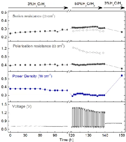
To further test the stability of cells based on the electrochemical switching concept, the same sample shown in Figure 2 which was operated in EC, FC, and RC modes, was also subjected to a long term test at 700 oC (Fig 3). Consistent with the other stability test this sample showed no degradation and further improved its FC performance from 0.38 to 0.54 W cm-2 at 700°C after EC/RC mode, suggesting, as shown above that additional particles were exsolved in the
process. This was also confirmed by a drop in electrode polarisation from 0.42 to 0.24 cm-2 as shown in Supplementary Fig 6.
In conclusion, we have shown that electrochemical switching offers not only a new route to robust, high-performance nanostructures and SOC devices, but also brings unprecedented simplifications for their preparation. While this concept synergises particularly well with high temperature electrochemical devices we expect it find wide applications well beyond this field.
Methods
Cell manufacture. The perovskite La0.43Ca0.37Ni0.06Ti0.94O3 (LCNT) was prepared by a modified solid state reaction described in detail previously.9 The as-prepared perovskite was milled in acetone in a planetary ball mill at 300 rpm for 2 h. LCNT and (La0.8Sr0.2)0.95MnO3 (LSM) – Zr0.89Sc0.1Ce0.01O2-γ (ScSZ) (50:50wt%) inks were made by mixing corresponding powders with Terpinol, KD1, and PVB in planetary miller for 2 h. The inks were screen-printed in a 0.5 cm2 active area on either sides of 18 mm diameter, 80-140 μm thick ScSZ button cells, in the configuration LCNT (10 μm) | ScSZ (80-140 μm) | LSM-ScSZ (20 μm). ScSZ electrolyte supports were fabricated by tape-casting and sintering at 1400 °C. LCNT was screen-printed first on one side of ScSZ and then fired at 1200 °C. The LSM-ScSZ ink was then screen-printed on the other side and fired 1100 °C. Ex-situ gas reduction was carried out in a controlled atmosphere furnace, under continuous flow of 5% H2/N2, at the temperatures indicated in the main text, with heating and cooling rates of 5 °C min-1.
Structural characterisation. The phase purity and crystal structure of the prepared perovskite was confirmed by using a PANalytical Empyrean X-ray Diffractometer operated in reflection mode. High-resolution secondary and backscattered electron images were obtained using a FEI Scios electron microscope. TEM and EDS analysis were carried out on a JEOL JEM-2010 machine. The exsolution characteristics plotted in Fig 1h were obtained as follows. Sufficiently flat, large enough areas oriented parallel to the viewing plane were identified. Secondary and backscattered electron images were then collected and analysed in Mathematica 10 for Windows as detailed in Supplementary Fig 7. The SEM images were converted to binary images where particles were outlined based on pixel contrast. From this, the number of particles as well as individual particle diameter can be calculated and therefore particles size distribution and the total amount of metal atoms contained within the particles by summation over the entire area. The exsolution depth was estimated by calculating the depth of a perovskite slab of equivalent area that would contain the observed amount of exsolved Ni atoms and assuming that only half of the Ni atoms exsolve (based on a previous report9). Multiple areas were subjected to this analysis for each sample and the average values were plotted in Fig 1h.
Electrochemical characterisation. The cells were mounted in a SOC testing jig equipped with gas control system. This included gas mass flow controllers (H2, N2), a pressurised liquid water supply, liquid flow meter, a controlled evaporator mixer and dew point probes, as described in detail previously.13Current–voltage (I–V) and impedance characteristics of the cells were measured in a 2-electrode, full-device arrangement and polarisation of the cell were analyzed with a Solartron 1280 B instrument. Electrochemical data were collected over the temperature range 700 and 900 °C in three different gas conditions, 50% H2O/N2 - EC, 3%H2O/H2 – FC and 50%H2O/H2 - RC. Air was continuously passed over the air electrode during FC, EC and RC experiments. For EC/RC tests, 19.4 g h-1 of water and 500 mL min-1 of N2 or H2 was supplied. For FC tests, 100 mL min-1 of H2 was supplied after passing through a water bubbler. Electrochemical switching was triggered by applying a 2 V potential. After current equilibration (Fig 1d), sweep voltammetry was conducted from 2 V (or from 1.7 V) to 0 V at a scan rate of 15 mV s-1 for EC/RC. For FC, after stabilization in OCV condition, voltammetry was scanned from OCV to 0 V. Impedance data were collected under 50 mV AC perturbation amplitude at 1.3 V, OCV, 0.7 V bias between 20000 and 2 Hz.
References
1. Irvine, J. T. S. et al. Evolution of the electrochemical interface in high-temperature fuel cells and electrolysers.
4
2. Graves, C., Ebbesen, S. D., Jensen, S. H., Simonsen, S. B. & Mogensen, M. B. Eliminating degradation in solid oxide electrochemical cells by reversible operation. Nat. Mater. 14, 239–244 (2015).
3. Irvine, J. T. S. & Connor, P. in Solid Oxide Fuels Cells: Facts and Figures (eds. Irvine, J. T. S. & Connor, P.) 163–180 (Springer London, 2013).
4. Jiang, S. P. A review of wet impregnation—An alternative method for the fabrication of high performance and nano-structured electrodes of solid oxide fuel cells. Mater. Sci. Eng. A 418, 199–210 (2006).
5. Jung, W., Gu, K. L., Choi, Y. & Haile, S. M. Robust nanostructures with exceptionally high electrochemical reaction activity for high temperature fuel cell electrodes. Energy Environ. Sci. (2014). doi:10.1039/c3ee43546f 6. Nishihata, Y. et al. Self-regeneration of a Pd-perovskite catalyst for automotive emissions control. Nature 418, 164–167 (2002).
7. Kobsiriphat, W. et al. Nickel- and Ruthenium-Doped Lanthanum Chromite Anodes: Effects of Nanoscale Metal Precipitation on Solid Oxide Fuel Cell Performance. J. Electrochem. Soc. 157, B279–B284 (2010).
8. Neagu, D., Tsekouras, G., Miller, D. N., Ménard, H. & Irvine, J. T. S. In situ growth of nanoparticles through control of non-stoichiometry. Nat. Chem. 5, 916–923 (2013).
9. Neagu, D. et al. Nano-socketed nickel particles with enhanced coking resistance grown in situ by redox exsolution. Nat. Commun. 6, (2015).
10. Tsekouras, G., Neagu, D. & Irvine, J. T. S. Step-change in high temperature steam electrolysis performance of perovskite oxide cathodes with exsolution of B-site dopants. Energy Environ. Sci. 6, 256–266 (2013).
11. Nenning, A. et al. Ambient Pressure XPS Study of Mixed Conducting Perovskite-Type SOFC Cathode and Anode Materials under Well-Defined Electrochemical Polarization. J. Phys. Chem. C (2015). doi:10.1021/acs.jpcc.5b08596
12. Sengodan, S. et al. Layered oxygen-deficient double perovskite as an efficient and stable anode for direct hydrocarbon solid oxide fuel cells. Nat. Mater. 14, 205–209 (2014).
13. Tsekouras, G. & Irvine, J. T. S. The role of defect chemistry in strontium titanates utilised for high temperature steam electrolysis. J. Mater. Chem. (2011). doi:10.1039/c1jm11313e
5
Figure 1. Electrochemical switching. (a), (b) and (c) schematic representations of redox exsolution, SOC gas reduction (5% H2/N2) and
electrochemical switching (by applying 2 V across the cell), respectively. (d) In blue, TGA data showing oxygen loss upon gas reduction as a function of time. In orange, cell current upon application of 2 V, also as a function of time (see (c)). This reduction kinetics is typical for titanate systems and implies two processes, one fast and one slow, corresponding to surface and bulk reduction,14 as highlighted. (f-g) SEM micrographs of La0.43Ca0.37Ni0.06Ti0.94O3-γ electrodes produced by (e) gas reduction at 900 °C for 20 h; (f) electrochemical switching, under 50% H2O/N2, 900 °C, 150 s; (g) replica of sample (f) after 100 h of fuel cell testing at 750 °C in 3% H2O/H2 at 0.7 V (see Supplementary Fig 5 for details). (h) Various characteristics of samples (f-g) plotted in parallel coordinate system (errors are smaller than the points). Polarisation and series resistance are given at OCV. Cells used in this figure had 140 μm thick electrolyte.
Figure 2. Solid oxide cell based on electrochemical switching.
Current-voltage curves (square symbols) illustrating operation at different temperatures in: (a) electrolysis mode under 50% H2O/N2, also showing the equivalent H2 production assuming 100% Faradaic efficiency; (b) fuel cell mode in 3% H2O/H2, also showing cell power curves (circle symbols); (c) reversible cell mode in 50% H2O/H2. The cell was based on a 80 μm thick electorlyte.
Figure 3. Long term stability. Cell voltage, power density,
[image:5.595.43.294.430.664.2] [image:5.595.331.533.432.660.2]