Abstract—The general effects of implementing skewing techniques in electrical machines are well known and have been extensively studied over the years. An important aspect of such techniques is related to the identification of optimal methods for analyzing and modelling any skewed components. This paper presents a fast, finite-element-based method, able to accurately analyze the effects of skew on wound-field, salient-pole synchronous generators in a relatively shorter time than the more traditional methods. As vessel for studying the proposed technique, a 400kVA alternator is considered. Analytical and theoretical considerations on the benefits of skewing the stator in the generator under analysis are preliminary carried out. A finite-element model of the machine is built and the proposed method is then implemented to investigate the effects of the skewed stator. Comparisons against more traditional techniques are presented, with focus on the analysis of the voltage total harmonic distortion and the damper bars’ currents. Finally, experimental tests are performed at no-load and on-load operations for validation purposes, with excellent results being achieved.
Index Terms—Skewing, Synchronous Generators, Permeance Function, Single-Slice, Multi-Slice.
I. INTRODUCTION
HE positive effects of implementing various methods of skewing in electrical machines (to improve the general quality of operation) are well-known throughout the machines and drive community. Providing the stator and/or the rotor of an electrical machine with an appropriate angular offset along the axial length can significantly reduce the air-gap flux density oscillations due to the tooth harmonics. This in turn results in notable improvements into the quality of current, voltage and torque waveforms.
Manuscript received November 28, 2016; revised March 6, 2017; accepted March 27, 2017.
S. Nuzzo, M. Galea and C. Gerada are with the Power Electronics, Machines and Control Group, University of Nottingham, Nottingham, UK (e-mail: [email protected]).
C. Gerada is with the Power Electronics, Machines and Control Group, University of Nottingham Ningbo, Ningbo, China (e-mail: [email protected]).
N. Brown is with Cummins Power Generation, Peterborough, UK; (e-mail: [email protected]).
However, it is also well-known that skewing does produce some drawbacks, from both an electromagnetic and manufacturing points of view. In fact, it may result in a deterioration of the general performance of an electrical machine, such as the reduction in the output voltage available at its armature terminals as well as the torque available at its shaft. Skewing can also negatively affect the manufacturing process, resulting in more time consuming and expensive procedures. In the next sections, an overview of how skewing is implemented in various electrical machines and how this is typically modelled is presented.
A. Skewing in Various Machines
The influence of axial skewing in induction machines (IM) has been widely investigated [1-4]. In general, IMs usually employ skew in the rotor bars rather the stator slots in order to simplify the manufacturing processes. On-going research related to IMs include investigations on the magnetic noise and the electromagnetic forces caused by skewing, as described in [5] and [6], where novel rotor structures are proposed at cost of increasing manufacturing times and costs. The non-uniformity of the flux density axial distribution and the loss behavior of a high-rated IM are investigated in [7].
In the field of permanent magnet (PM) machines, the analysis of skewing and its effects has also been widely dealt with, in particular for low speed applications, where high torque quality is often required. In such cases, skewing the stator slots or the PMs themselves [8, 9] can result in a significant reduction of the cogging torque component [10-14], which in turn produces improvements in the quality of the on-load torque. The challenge of minimizing the torque pulsations has been dealt with in different types of PM machines in recent literature. For example, [15] has shown that skewing in regular steps does not achieve significant improvements in the torque ripple of surface-mounted PM machines. An improved skewing method is presented in [16], where a spoke-type interior PM machine is optimized for torque ripple minimization without compromising the available average torque. An asymmetrical, bidirectional magnet skewing technique is instead proposed in [17], for a modular multi-stage axial-flux PM machine. An authoritative review of magnet skewing techniques for double-rotor axial-flux disk motors is provided in [18].
In recent years, significant effort related to improving the torque quality in the field of synchronous reluctance motors
A Fast method for Modelling Skew and its
Effects in Salient-Pole Synchronous
Generators
Stefano Nuzzo,
Student Member, IEEE
, Michael Galea,
Member, IEEE,
Chris Gerada,
Senior Member, IEEE
and
Neil Brown
(SRMs) has also been registered [19, 20]. In particular, the benefits of skewing the rotor, in combination with an appropriate stator winding design, are highlighted in [21]. In [22], it is highlighted how the torque ripple of a SRM can be further reduced if the skew is applied to an optimal asymmetric rotor structure. The 3-D effects associated with skewing are examined in [23], where it is shown how end-effects and axial interactions between skewed steps can considerably deteriorate the torque ripple effects in SRMs.
B. Skewing in Synchronous Generators
A very important field which for historic reasons has never fully considered the importance of skewing is that related to the area of salient-pole Synchronous Generators (SGs). The ever-increasing power quality and efficiency requirements related to the power generation is projecting designers and manufacturers of SGs to consider every aspect related to these pressing challenges [24-27]. In particular, special focus is being given to the total-harmonic-distortion (THD) of the output voltage. For example, while [28] and [29] show how the THD can be improved and optimized without resorting to skewing techniques, the work in [30] investigates how the choice of an optimal skew angle, combined with an increased air-gap thickness, can reduce the noise level within the standards and improve the THD in a hydro-generator. The study performed in [30] also aims to achieve an understanding of how the field distribution, the damper cage currents and the rotor pole face losses are affected by stator skewing and provides a wide range of experimental data at no-load and full-load operations. In [31], a detailed analysis of a tubular SG is carried out in order to investigate the effects of stator skewing and damper bar pitch on the voltage waveform and the damper cage loss. For the same aspects, large SGs with an axial skew are analyzed in [32] and [33].
Considering all the above, it is clear that skewing in SGs is rapidly becoming an important design aspect. While traditionally it has been very roughly implemented, today skewing and its effects need to be considered from a very early design stage and to an appropriate level of detail.
C. Modelling of skew
In this context, predicting the skewing’s effects in a fast and accurate way is thus very important in the design routine of an electrical machine, in particular when heavy design iterations are required. Classical approaches for modelling skewing consist in 3-D calculations of air-gap permeances which also include axial field variations [34]. Fully analytical models (that consider skew and its effects) have also been proposed by implementing the winding function method [35] and the subdomain modelling technique [36, 37]. With recent improvements in computational capabilities and modelling accuracy allowed by numerical methods, a number of hybrid analytical/Finite-Element (FE) techniques have been proposed [32, 38, 39] as well as purely FE models [40]. A common approach is to use the multi-slice technique [1-3, 41, 42], which comprises the creation of a number of cross-sections of the machine along its axial length and the simultaneous simulation of these slices. The multi-slice approach has been proposed in [42] in order to overcome inaccuracies resulting from averaging processes in machines with short-circuited
cages, i.e. IMs and SGs. Such a study also shows how averaging processes can be used for SGs if the magnetic field does not significantly change along the axial direction. In [43], the multi-slice method has been extended to a magnetic equivalent circuit model and a constraint is imposed to ensure that axial currents are equal in each slide. Although all these techniques are very accurate, they come at cost of high computational resources which are not suited for iteration-heavy designs.
D. Objective
In this paper, a technique for the modelling and the analysis of skew effects in electrical machines (with a focus on SGs) is proposed and investigated. Updates on the approach investigated in [44] are implemented onto a 400kVA SG in order to predict the no-load and on-load THD of the machine’s output voltage. Using the proposed modelling technique, then a harmonic analysis and a theoretical explanation of the benefits due to the stator skew in the generator under analysis are carried out and presented in Section II. The technique and its results are then compared to the two more common approaches (for modelling of skew), via a purposely-built 2-D, Single-Slice (SS) FE model. The mentioned ‘common’ techniques are
1) the averaged-slice (AS) technique, where a set of 2-D slices with appropriate shift between rotor and stator are created and then post-processed by using averaging processes;
2) the multi-slice (MS) technique, where a number of 2-D slices with appropriate shift between rotor and stator are created and then simultaneously solved.
The above-proposed method is thus used for the analysis of voltage waveforms, damper cage induced currents and associated losses in SGs. As shown below in the paper, excellent results in terms of modelling, accuracy and time consumption are achieved. Experimental tests are performed to prove the validity of the fast, proposed SS technique.
E. The Platform
As vessel for this study, a particular salient-pole SG is considered. The machine is a four pole alternator, with a rated apparent power of 400kVA, designed to provide a rated voltage of 400V, at 50Hz and at 0.8 power factor. Some of the features of the considered generator are the followings: 1) the stator and rotor have a laminated structure and made
by the same electromagnetic steel, i.e. a M700-65A material;
2) the stator is skewed by one slot pitch allowing to cancelling the slot harmonics on the output voltage; 3) the number of slots-per-pole-per-phase q is 4 with a
double-layer winding structure;
4) the stator winding is short-pitched by 4 slots in order to eliminate the third harmonic on the phase-to-neutral voltage. In fact, the generator is also designed to operate under single-phase conditions;
5) the number of parallel circuits on the stator winding is 2; 6) the stator slot opening has an angular span which is about
7) the rotor is such that the airgap is constant along the entire angular span of the pole shoes;
8) the angular pole span covers the 75% of the whole pole pitch;
9) the aspect ratio as well as the split ratio of the machine are equal to 0.7, in correspondence of the minimum airgap thickness;
10) the rotor is equipped with a damper cage symmetrically displaced around the polar axes;
11) the damper cage end connections are created by press plates made out of aluminum, i.e. laminations thicker than the rotor ones.
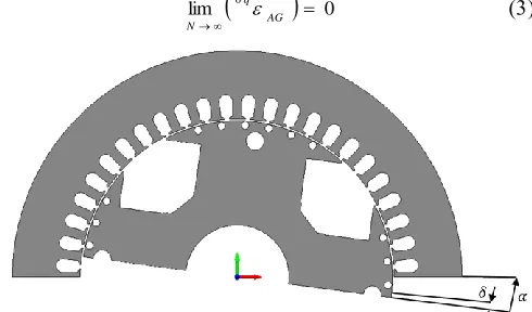
The 2-D cross-section of the considered machine is shown in Fig. 1, where some of the features described above can be observed. Knowledge of these features allows for a comprehensive description of the electromagnetic quantities which are introduced in the following section.
II. ANALYTICAL MODELLING OF SKEWING
A. Model Description
Although skewing is inherently a 3-D feature, some interesting considerations can be developed when a 2-D approximation is considered in conjunction with the application of the equivalent circuits’ theory for the modelling of the main electromagnetic phenomena occurring in electrical machines.
It is well-known that the induced voltages in electrical machines are composed by a resistive and an electromagnetic component. It is also well-known that the latter is due to the variation of the flux linkage with respect to the time. One possible way to derive the fluxes linked with the machine’s phases and thus solve the electromagnetic problem is to evaluate the air-gap flux density distribution BAG(λ,α) as shown in (1), where λ is the angular reference frame locked to the rotor, α the mechanical variable associated with the rotor position, F(λ,α,i) is the air-gap mmf and P(λ,α) is the permeance function [2]. The latter is described in (2), where µ0 is the permeability of air and εAG(λ,α)is the variable air-gap thickness evaluated along the tangential direction.
BAG (,,i) P(,)F(,,i)
) , (
1 )
,
( 0
AG
P
Considering the above, it is clear that all the information related to the anisotropies present in the machine are contained in the function εAG(λ,α). It is also clear that, because of the intrinsic geometrical symmetry of the majority of electrical machines, this function exhibits a periodicity of π/p, where p is the number of pole pairs.
The function εAG(λ,α) can be determined by difference between rs(λ,α)and rr(λ,α), which represent the stator and rotor
radii respectively, evaluated along the tangential direction. In particular, these 2 functions can be seen as two magnetically equipotential surfaces which are perpendicular, at any position along the tangential direction, to the flux lines crossing the
air-gap. In other words, they retrace the shapes of the stator and rotor surfaces which face the air-gap.
The above compiles and collates all the geometrical quantities which are necessary to solve the electromagnetic problem. Therefore, it is now possible to exploit this and thus draw some analytical considerations on the positive and negative effects that skewing produces on such quantities and in turn on the electromagnetic performance of the particular SG considered in this paper.
B. Effects of Skewing on the Airgap Thickness Function
Considering all the above, it is clear that all the slotting effects can be implemented in the function rs(λ,α). This is done by considering step functions in correspondence of the stator slot openings. Step functions are also used to model the maximum and minimum radial distances of the rotor surface from the axis, i.e. rr(λ,α), at a fixed rotor position. It is then easy to evaluate the function εAG(λ,α). This is shown in Fig. 2, where the slot harmonic can be easily observed. It is clear that this slot harmonic will be present in the permeance function P(λ,α) and thus in the airgap flux density BAG(λ,α). As expected, one possible solution to mitigate the effects of the slot harmonics on the output voltage is to axially skew the stator of the SG.
To implement the skewing in the variable airgap thickness function, one can consider a number N of 2-D cross sections of the machine along the axial direction. Each slice is shifted from each other by a submultiple δ of the skewing angle α, as shown in Fig. 1. In practice, this corresponds to a shift of rs(λ,α) and this is recalculated by averaging each waveform over the number N of slices considered. In order to show this concept, the waveform obtained in Fig. 2 (where the skewing is not considered and thus N=1) is compared with the waveforms obtained when N=5 and N=9. This is shown in Fig. 3, where it can be observed how the slotting effect is reduced when considering an increasing number of slices. In the case of the SG analyzed in this paper, where a continuous (i.e. not stepped) skewing is applied to the stator, it is obvious that an accurate implementation of this machine’s feature in the airgap thickness function implies the choice of a theoretically infinite number of slices (N=∞). This results in the interesting result given in (3), where
AG q
6 is the first slot harmonic,
evaluated under one pole pair.
lim
6
0
AG
q
N
[image:3.612.319.564.562.706.2]
Fig. 2. Variable airgap thickness function εAGvs. angular displacement λ.
Fig. 3. Zoom on the variable airgap thickness function – comparison between an un-skewed (N=1) and a skewed stator (N=5 and N=9).
C. Final Considerations
In the previous sections, some analytical considerations on the effects that skewing can have on the airgap thickness function have been carried out. Although simplified shapes of rs(λ,α) and rr(λ,α) have been considered, some important results can be observed. In particular, it has been shown how skewing can mitigate the harmonics due to the stator slot openings (Fig. 3) and, in the case of a continuous stator axial skewing, a theoretical, complete elimination of these harmonics can be achieved (see (3)). This results in the elimination of the slotting effect on the permeance function described by (2) and thus in the airgap flux density function defined by (1), which in turn allows for improvements in the output voltage waveform.
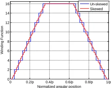
It is also important to observe that, by applying the same concept of averaging the waveforms obtained by considering N axial slices of the machine, it is possible to ‘improve’ also the winding functions which describes the machine’s phases. This concept is shown in Fig. 4, where the number of slices used is 5. It can be observed that the skewed winding function (in red) is much more sinusoidal-distributed of that of the un-skewed one (in blue). The main effect is therefore that of producing a better winding distribution. However, this comes at cost of reducing the winding factor (by 0.3% in the case of Fig. 4, where N=5) which in turn propagates in a reduction of
the performance of the machine. It is also clear that, when an increased number of slices is used for averaging the blue waveform, a further reduction of the winding factor can be observed, again highlighting that skewing is an optimizable feature in the design stage of electrical machines.
Fig. 4. Stator winding function – comparison between an un-skewed and a skewed stator.
All the above highlights that the effects due to the skewing can significantly affect the internal electromagnetic phenomena occurring in electrical machines. Therefore, it is of paramount importance to model it in a fast and accurate way, especially for iterative design purposes. Although the above has shown that analytical models can be used for carrying out very interesting considerations related to the skewing, the complexity of the phenomena related to the “slotting” effects, the non-linearity associated with the magnetic materials and the eddy currents and hysteresis-related phenomena would imply the use of some tuning procedure and/or simplifying assumptions which will lead to more inaccurate results when compared with a FE analysis. Also, the induced nature of the damper cage currents would however require a numerical solution.
Considering all the above, in the next sections, a single-slice, 2-D FE modelling technique is proposed and compared with the most known 2-D FE approaches and to experimental measurements for validation purposes.
III. THE PROPOSED SINGLE-SLICE FEMODEL
A. Model Description
It is clear that a 3-D FE model would be ideal for the analysis of the SG considered in this work. In fact, in addition to the fact that stator skewing is an inherently 3-D feature, there are other aspects to be considered. In particular, the end windings’ effects, the presence of the damper cage and the end connections are important for an accurate analysis. However, a full 3-D analysis is very time consuming, so in order to understand the effectiveness of an equivalent methodology, a 2-D FE model of the 400kVA generator is built. A number of lumped circuital resistances, as explained in [29], are considered in the model to account for the end windings’ ohmic effects. All the observations described above lead to consider that a 2-D, transient with motion evaluation can be used for accurately taking into account the most critical aspects related to the end effects without resorting to the 3-D
0 0.2/p 0.4/p 0.6/p 0.8/p 1/p
0 50 100 150
A
ir
-g
a
p
T
h
ickn
e
ss
[m
m
]
0.35/p0 0.4/p 0.45/p 0.5/p 0.55/p 0.6/p 0.65/p
2 4 6
Normalized Angular Position
0.4/p 0.45/p 0.5/p 0.55/p 0.6/p
1.5 2 2.5 3 3.5 4 4.5 5
Normalized angular position
A
ir
-g
a
p
T
h
ickn
e
ss
[m
m
]
N=1 N=5 N=9
0 0.2/p 0.4/p 0.6/p 0.8/p 1/p
0 2 4 6 8 10 12 14 16
Normalized angular position
W
in
d
in
g
F
u
n
ct
io
n
[image:4.612.347.526.120.262.2] [image:4.612.68.274.254.410.2]modelling. Also, with respect to the damper winding, each bar is accurately modelled as a solid conductor. Thus, in the name of accuracy, the potential skin effect resulting from the slot harmonics is also taken into account. This is a very important aspect, as the analysis of the damper cage currents and ensuing losses represent one of the goals of this work.
Considering the FE model described above, a SS method is proposed for the analysis of the skewing. A transient with motion evaluation of an un-skewed machine is done, which comprises flexibility in terms of simulating different operating conditions according to the type of load considered in the circuit coupled to the FE model. In other words, the no-load condition is simulated by setting a resistance equal to a practical infinite value, while the on-load operation is analyzed by the setting the circuital lumped parameters (resistance, inductance and capacitance) according to the given apparent power and power factor.
The key point of the proposed method is choosing a simulation angle step δ equal to a submultiple of the skewing angle α. The smaller the simulation angle step, the more accurate the post-processed electromagnetic quantities, without significantly compromising the computational times. These quantities (i.e. fluxes linkages, voltages, currents, etc.) are phase shifted by the selected angle δ and averaged over the skewing angle, as given in (4) for the generic scalar quantity A(θ). For the sake of clarification, it is worth to point out that this process is also applied for the evaluation of the damper cage currents and losses.
2 /
2 /
) ( )
( A
A
The averaging process shown in (4) assumes that there are no variations of the magnetic state of the skewed machine along the axial direction. It is also true that averaging processes can lead to inaccuracies in machines equipped with short-circuited rotor cages [40]. However, the main aims of this work are 1) proposing a very fast technique for modelling the skewing
in everyday, company-based design of SGs;
2) proving that this method can be very accurate for estimating some critical standard grid requirements, such us the THD of the no-load and on-load voltages;
3) highlighting that the limitations of the proposed method for the estimation of more complex quantities, such as the currents induced in the damper cage, are not significantly critical.
The next section therefore deals with the analysis of the results obtained with the SS technique, at no-load and at full-load operations. The results are not presented on their own, but are illustrated directly in the validation comparisons with the results from the AS and the MS models. These are shown in Figures 6 - 10.
B. Model Validation
This section is aimed at comparing the proposed SS method described above with the two most common ways used to model the skewing in electrical machines, namely the AS and the MS techniques. The major features of these methods are highlighted below:
1) The AS technique: it consists in creating a set of 2-D FE models, different from each other only for the initial phase shift between rotor and stator positions. Each model is then solved separately and the results are post-processed by averaging processes. The higher the number of models being used, the more accurate the field solution, but the required computational time is also compromised. This technique is perfectly suitable for modelling stepped-based skewing, which for example is very common in PMMs.
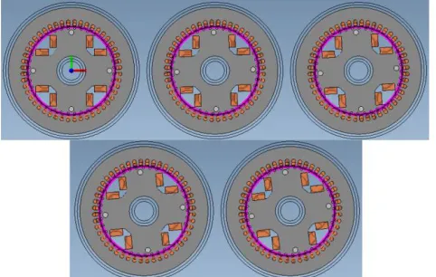
2) The MS technique: it consists in creating a number of 2-D slices with a specific phase shift between rotor and stator positions, according to the skew angle (Fig. 5). These slices are then solved simultaneously. This constraints the currents flowing in skewed windings to be the same along the axial direction, thus allowing for much more accuracy than an averaging procedure. This technique is the most accurate amongst 2-D FE methods for modelling the skewing. On the other hand, it requires significant computational resources.
An accurate, preliminary sensitivity analysis has been performed aiming to select the most appropriate number of slice N to be used for comparison purposes. The results of such analysis have led to consider a scheme with 5 slices. This number is chosen on the basis that no significant modifications on the electromagnetic quantities are observed when an increased N is used. The three techniques are thus compared with a number of slices equal to 5 being used for all of them. All the results at no-load and full-load operations are shown in the following sections.
Fig. 5. The multi-slice FE model, with 5 slices simultaneously evaluated.
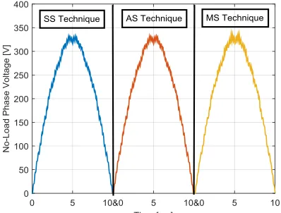
a) No-Load
[image:5.612.320.561.424.577.2]and total RMS for the skewless machine, are also shown to emphasize the advantages that skewing can achieve.
In Fig. 7 and 8, the comparison is carried out in terms of damper cage induced currents. In particular, Fig. 7 shows a comparison amongst the current’s waveforms induced in one damper bar (e.g. the bar on the pole tip) evaluated with the three different methods. Fig. 8 compares the rms values (y-axis) of such currents induced on the damper bars (x-(y-axis) of one salient-pole. In this case, a good match amongst the results obtained with the three techniques can be seen, highlighting the validity of the proposed method at no-load operation. However, some differences can be observed amongst the currents in bars 3 and 4, especially when evaluated with the MS technique. This is due to the fact that the currents are constrained to be the same in each bar of this winding, and are not evaluated according to the same averaging concepts as the SS and the AS techniques do.
Fig. 6. No-load terminal voltage – Comparison amongst the three methods.
TABLE I
THD AND RMS VALUES – COMPARISON AMONGST THE THREE TECHNIQUES
---
No-load Phase Voltage
SS AS MS Skew-less
THD 2.193% 2.183% 2.221% 5.58%
Total RMS 230.01V 230.05V 230.25V 231.96V
[image:6.612.332.536.60.224.2]Fig. 7. No-load currents induced in one damper bar – comparison amongst the three techniques.
Fig. 8. No-load, rms values of damper cage currents – Comparison.
b) Full-Load
[image:6.612.68.267.258.409.2]Classical averaging processes used to model skewed electrical machines can lead to inaccuracies in predicting the performance, especially when these are equipped with short-circuited windings. At full-load operation, besides the effects due to the slot harmonics, additional damper cage currents are induced by the armature reaction [28]. As well as for the no-load operation, in order to validate the SS method, the damper cage currents are evaluated with the proposed technique and then compared with the well consolidated AS and MS simulations. An excellent similarity amongst the results of Fig. 9 can be observed, where the rms values of the damper cage currents induced into the bars placed on one pole are shown. Also at full-load operation the damper cage currents predicted with the SS technique are very similar to those evaluated with the AS and the MS methods and the percentage error is very low. When considering the advantages in terms of computational times, then this relative accuracy is of course an added advantage for the proposed technique. The full-load stator currents are compared in Fig. 10, showing again a very good similarity amongst the results.
[image:6.612.322.540.501.673.2]Fig. 10. Stator phase currents – Comparison.
For the sake of completeness, the damper cage losses are computed with the 3 different techniques and compared relative to each other but also to the case of a skew-less configuration. In Table II, it can be observed that losses are reduced by 2.2% when skewing is applied, as the slot harmonic effect is attenuated. Although skewing can affect other loss components [33], such as the pole face losses, and can lead to an increased field current to compensate for the ensuing output voltage drop (see Table I), it can be concluded that this stator feature does not significantly affect the overall efficiency of the considered platform.
TABLE II
DAMPER CAGE LOSS – COMPARISON AMONGST THE THREE TECHNIQUES Damper Cage Loss
SS AS MS Skew-less
1136W 1131W 1126W 1155W
IV. EXPERIMENTAL MEASUREMENTS
All the above has proven the validity of the fast single-slice FE technique, proposed for the modelling of skewing and its effects in the considered 400kVA SG, with validation against the well-known and consolidated AS and MS techniques. However, further validation is necessary because of the 3-D nature of the skewing. Hence, experimental measurements have been performed on an available platform. This is briefly described in the next section and tests at several load conditions are then used to compare and validate the proposed technique. In order to reach a certain level of accuracy, the simulation angle step δ is chosen in such a way that the number of slices used to extrapolate the current and voltage waveforms is equal to 21.
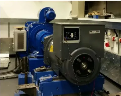
A. The experimental platform
[image:7.612.61.269.64.224.2]The experimental platform of the particular SG considered in this paper consists of an induction machine drive, acting as the prime mover, whose speed loop controls the frequency of the SG, which is mounted on the same shaft of the motor. The experimental set-up can be observed in Fig. 11.
Fig. 11. Experimental test bench of the considered SG.
A combination of testing methods including a load bank and the classical back-to-back (slave-machine) method were used. For up to half load ratings, the machine terminals are connected to a resistive load bank, consisting of variable resistances whose power can be remotely varied up to 200kW, thus giving the opportunity of more discretization in the testing samples. The classical back-to-back method was used to perform measurements at full-load rated operation. All the experimental tests have been carried out with the machine’s AVR connected in order to maintain the output voltage at its rated value while changing the load.
B. No-Load Test
The no-load test is performed with the stator terminals open-circuited. The voltage waveforms and harmonics are recorded during the test. The voltage THD is evaluated and compared with the calculated value determined through the proposed technique. The results are shown in Table III (first row), with an excellent match being achieved at no-load operation.
C. Test at 50kVA, 100kVA and 200kVA, at unity power factor
These tests are performed with the resistive load bank set at 50kW, 100kW and 200kW, respectively. The voltage waveforms and harmonics are registered during the measurements. The voltage THD is determined and then compared with that evaluated through the SS technique. Table III also shows the comparison at different loading levels (referring to the unity power factor rows), where a very good similarity can be observed.
TABLE III
EXPERIMENTAL AND FE RESULTS – COMPARISON AT DIFFERENT LOADING AND POWER FACTOR
Loading – Power Factor
Voltage THD
FE Experimental
No-Load 1.26% 1.34%
50kVA – 1pf 1.13% 1.19%
100kVA – 1pf 1.39% 1.26%
200kVA – 1pf 2.44% 2.01%
D. Test at 400kVA, at 0.8 power factor
This test is carried out with the considered platform’s terminals connected to those of the ‘slave’ machine. The rated full-load condition has been evaluated, in order to compare the voltage THD between the FE and experimental evaluations. The last row of Table III shows an excellent similarity between the above-mentioned results.
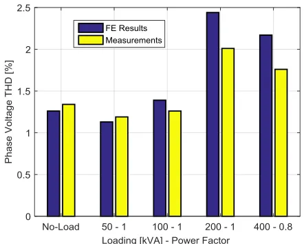
E. Summary and Final Considerations
Experimental tests have been carried out in order to prove the validity of the SS technique. The results in terms of voltage THD have been compared to the proposed method, resulting in an excellent similarity, which is clearly observable in Fig. 12. In this figure, an important aspect to note is the increasing discrepancy between the expected and measure results, relative to the increasing of the loading level. This is mainly due to the effects of the machine’s armature reaction. However an important factor to consider is the inaccuracies intrinsically included in the averaging process, inherent to the proposed SS, FE technique. While it is acknowledged and clear that averaging the current induced in the armature windings (and in the damper cage) is conceptually incorrect, it has however been shown to be a reliable approximation. In fact, as shown in Section III.B, even more complex and more time-consuming techniques (such as the MS method) produce similar results. Potential improvements can be achieved by increasing the number of slices utilized for modelling the stator skew, i.e. reducing the simulation time step in the SS technique. However, this would come at the cost of more computational time and resources.
V. CONCLUSIONS
This paper presents a fast, finite-element-based method to accurately predict the output voltage and current THD in a stator-skewed synchronous generator, at both no-load and on-load operations. As vessel for studying the proposed single-slice method, a 400kVA alternator was considered.
Theoretical considerations on the benefits of skewing the stator in the generator under analysis were preliminary carried out. A FE model of this machine was then built to prove the proposed technique. This was then compared for validation purposes with the well consolidated average-slices and multi-slice techniques, at both no-load and full-load conditions, with an excellent match being achieved, indicating the validity of the technique. At this stage, focus was given to the damper cage behavior, highlighting some limitations of the SS technique in estimating more complex quantities to analyze, such as the currents induced in the bars.
Finally, in order to further validate the SS method, experimental measurements were performed at no-load and at different loadings and power factors, where the voltage THD comparisons showed an excellent similarity. At no-load, the maximum error was 5.97%. The validation however highlighted a weakness of the technique when going towards the higher loading ratings. This is associated with the machine’s armature reaction and the averaging processing philosophy employed by the technique. However it is also important to note that even with this perceived challenge, the maximum error at full load was 18.9%, again highlighting the
adequateness of the modelling technique. Also, although an increased number of slices (21) is considered for the experimental validation of the SS method, it allows for a reduction of the computational time by 4.5 hours and by 22 hours, in comparison with the AS and the MS techniques respectively, when 5 slices are used for all of those models. It can therefore be safely concluded that the proposed method does achieve the main goal of a fast but accurate technique for modelling skew in SGs.
Fig. 12. Phase Voltage THD – Comparison between FE and experimental results.
It is the authors’ intention to continue the development of this technique and present findings in future publications. A first step will be focused on the evaluation of appropriate compensation factors, aimed at overcoming the mentioned full-load inaccuracies. After that, it is the intention to investigate the flexibility of the technique when applied to different platforms.
REFERENCES
[1] C.I. McClay, S. Williamson, “Influence of rotor skew on cage motor losses,” IEE Proc. on Electr. Power Appl., Sep. 1998, Vol. 145, Iss.5, pp. 414-42.
[2] A. Tenhunen and A. Arkkio, “Modelling of induction machines withskewed rotor slots,” IEE Proc. Electr. Power Appl., vol. 148, no. 1, pp. 45–50, Jan. 2001.
[3] D. G. Dorrell, P. J. Holik, and C. B. Rasmussen, “Analysis and effects of inter-bar current and skew on a long skewed-rotor induction motor for pump applications,” IEEE Trans. Magn., vol. 43, no. 6, pp. 2534–2536, Jun. 2007.
[4] K. J. Binns, R. Hindmarsh, and B. P. Short, “Effect of skewing slots on flux distribution in induction machines,” Proc. Inst. Elect. Eng., vol. 118, no. 3/4, pp. 543–549, Mar./Apr. 1971.
[5] L. Wang, Xiaohua Bao, Chong Di, Jiaqing Li, “Effects of novel skewed rotor in squirrel-cage induction motor on electromagnetic force,” IEEE Trans. Magn., Vol 41, Issue Il, Nov. 2015.
[6] S. L. Ho, S. Niu, and W. N. Fu, “A novel solid-rotor induction motor with skewed slits in radial and axial directions and its performance analysis using finite element method,” IEEE Trans. Appl. Supercond., vol. 20, no. 3, pp. 1089–1092, Jun. 201
[7] Handgruber, A. Stermecki, O. Bıró, A. Belahcen, and E. Dlala, “3-D eddy current analysis in steel laminations of electrical machines as acontribution for improved iron loss modeling,” in Proc. 20th Int. Conf. Electrical Machines, Marseille, France, 2012.
[image:8.612.322.543.165.342.2][9] S. M. Hwang, J. B. Eom, Y. H. Jung, D. W. Lee, and B. S. Kang, “Various design techniques to reduce cogging torque by controlling energy variation in permanent magnet motors,” IEEE Trans. Magn., vol. 37, no. 4, pp. 2806–2809, Jul. 2001.
[10] Chu W Q, Zhu Z Q., “Investigation of Torque Ripples in Permanent Magnet Synchronous Machines With Skewing[J],” IEEE Trans. Magn., 2013, 49(3):1211 - 1220.
[11] Letelier, A.B,;. González, D.A,; Tapia, J.A,; Wallace, R.R, and Valenzuela, M.A., “Cogging Torque Reduction in an Axial Flux PM Machine via Stator Slot Displacement and Skewing,” IEEE Trans. Ind.. Applic., vol. 43 , no. 3, May/June 2007, pp. 685-693.
[12] W. Fei and Z. Q. Zhu, “Comparison of cogging torque reduction in permanent magnet brushless machines by conventional and herringbone skewing techniques,” IEEE Trans. Energy Convers., vol. 28, no. 3, pp. 664–674, Sep. 2013.
[13] R. Lateb, N. Takorabet, and F. Meibody-Tabar, “Effect of magnet segmentation on the cogging torque in surface-mounted permanent-magnet motors,” IEEE Trans. Magn., vol. 42, no. 3, pp. 442–445, Mar. 2006.
[14] T. Raminosoa, C. Gerada, M. Galea, “Design Considerations for a Fault-Tolerant Flux-Switching Permanent-Magnet Machine,” IEEE Trans. Ind. Electron., vol. 58, no. 7, pp. 28182825, July 2011.
[15] R. Islam and I. Husain, “Permanent-magnet synchronous motor magnet designs with skewing for torque ripple and cogging torque reduction,” IEEE Trans.Ind. Appl., vol. 45, no. 1, pp. 152–160, 2009.
[16] W. Zhao, T. A. Lipo, and B.-I. Kwon, “Torque pulsation minimization in spoke-type interior permanent magnet motors with skewing and sinusoidal permanent magnet configurations,” IEEE Trans. Magn., vol. 51, no. 11, Nov. 2015, Art. no. 8110804.
[17] H. Xie, X. Wei, Y. Liu, Y. Feng, Y. Zhang, X. Yang, and K. Yan, “Research of asymmetrical bidirectional magnet skewing technique in modular multi-stage axial flux permanent magnet ”, IEEE Trans. Magn., Vol 51, no. 3l, March 2015.
[18] Aydin M., Gulec M., “Reduction of Cogging Torque in Double-Rotor Axial-Flux Permanent-Magnet Disk Motors: A Review of Cost-Effective Magnet-Skewing Techniques With Experimental Verification[J],” IEEE Trans. Ind. Electron., 2014, 61(9): 5025 – 5034. [19] Vagati. A., Pastorelli. M., Francheschini. G., Petrache. S.C., “Design of
low-torque-ripple synchronous reluctance motors,” IEEE Trans. Ind. Appl., vol.34, no.4, pp.758-765, Jul/Aug 1998.
[20] N. Bianchi, S. Bolognani, D. Bon, Pre, x, and M. D., “Rotor Flux-Barrier Design for Torque Ripple Reduction in Synchronous Reluctance and PM-Assisted Synchronous Reluctance Motors,” IEEE Trans. Energy Conv., vol. 45, pp. 921-928, 2009.
[21] Xola B. Bomela, Maarten J. Kamper, “Effect of Stator Chording and Rotor Skewing on Performance of Reluctance Synchronous Machine” , IEEE Trans. on Ind. Appl., vol. 38, no. 1, January/February, 2002. [22] E. Howard, M. Kamper, and S. Gerber, “Asymmetric flux barrier and
skew design optimization of reluctance synchronous machines,” IEEE Trans. Ind. Appl., vol. 51, no. 5, pp. 3751–3760, Sep./Oct. 2015. [23] Lazari P., Wang J.,Sen B., “3-D effects of rotor step-skews in permanent
magnet-assisted synchronous reluctance machines”, IEEE Trans. Magn., vol. 51, no. 11, Nov. 2015.
[24] A. Tessarolo, C. Bassi, D. Giulivo, ”Time-stepping finite-element analysis of a 14-MVA salient-pole shipboard alternator for different damper winding design solution,” IEEE Trans. Ind. Electron., Vol. 59, No. 6, pp. 2524-2535, June 2012.
[25] S. Jordan, C. Manolopoulos, J. M. Apsley, ”Winding configurations for five-phase synchronous generators with diode rectifiers,” IEEE Trans. Ind. Electron., vol. 63, no. 1, pp. 517-525, Jan. 2016.
[26] K. S. Jiji, N. H. Jayadas, C. A. Babu, ”FEM-based Virtual Prototypingand Design of Third Harmonic Excitation System for Low-Voltage Salient-Pole Synchronous Generators,”, IEEE Trans. Ind. Electron., vol. 50, no. 3, May/June 2014.
[27] G. Traxler-Samek, T. Lugand, A. Schwery, “Additional losses in the damper winding of of large hydrogenerators at open-circuit and load conditions,” IEEE Trans. Ind. Electron., vol. 57, no. 1, pp. 154-160, Jan. 2010.
[28] Nuzzo S., Galea M., Gerada C., Gerada D., Mebarki A., Brown N. L., “Damper Cage Loss Reduction and No-Load Voltage THD Improvements in Salient-Pole Synchronous Generators”, Proc. in Power Electronics, Machines and Drives (PEMD 2016), 8 th IET International Conference on., 2016.
[29] Nuzzo S., Degano M., Galea M., Gerada C., Gerada D., Brown N. L., “Improved damper cage design for salient-pole synchronous generators”, IEEE Trans. Ind. Electron., 2016.
[30] H. Karmaker and A. Knight, “Investigation and Simulation of Fields in Large Salient-Pole Synchronous Machines with Skewed Stator Slots”, IEEE Trans. Energy Conv., vol. 20, p. 604, September 2005.
[31] Zhen-nan, F., Yong, L., Li, H and Li-dan, X., “No-Load Voltage Waveform Optimization and Damper Bars Heat Reduction of Tubular Hydrogenerator by Different Degree of Adjusting Damper Bar picth and skewing Stator Slot,” IEEE Trans. Energy Conv., Vol 28. no. 3, Sept. 2013.
[32] A. M. Knight, S. Troitskaia, N. Stranges, and A. Merkhouf, “Analysis of large synchronous machines with axial skew, part1: Flux density andopen-circuit voltage harmonics,” IET Electr. Power Appl., vol. 3, no. 5, pp. 389–397, 2009. pp. 389–397, Sep. 2009.
[33] A. M. Knight, S. Troitskaia, N. Stranges, and A. Merkhouf, “Analysis of large synchronous machines with axial skew—Part 2: Inter-bar resistance, skew and losses,” IET Elect. Power Appl., vol. 3, no. 5, pp. 398–406, Sep. 2009.
[34] Ostovic V., Dynamics of saturated electrical machines. New York, NY, USA: Springer-Verlag, 1989.
[35] J. M. Gojko, D. D. Momir, and O. B. Aleksandar, “Skew and linear rise of mmf across slot modeling - winding function approach,” IEEE Trans. Energy Conv., vol. 14, no. 3, pp. 315–320, Sep 1999.
[36] Xia C., Zhang Z., Geng Q., “Analytical modelling and analysis of surface mounted permanent magnet machines with skewed slots,” IEEE Trans. Magn., vol. 51, no. 5, May 2015.
[37] M. Galea, L. Papini, He Zhang, C. Gerada, T. Hamiti, “Demagnetization Analysis for Halbach Array Configurations in Electrical Machines”, IEEE Trans. Magn,, vol. 51, no.9, Sep. 2015, Art. ID 8200210. [38] Y. S.Chen, Z. Q. Zhu, “Calculation of d- and q-axis inductances of PM
brushless ac machines accounting for skew,” IEEE Trans. Magn., vol.41, no.10, pp.3940-3942, Oct.2005.
[39] Afsari kashani, S.; Heydari, H.; Dianati, B., “Cogging Torque Mitigation in Axial Flux Magnetic Gear System Based on Skew Effects Using an Improved Quasi 3-D Analytical Method.,” IEEE Trans. Magn., vol. PP, no.99, pp.1,1, Sept.-Oct. 2015.
[40] Dziwniel P., Boualem B., Piriou F., Ducreux J. P., Thomas P., “Comparison between two approaches to model induction machines with skewed slots”, IEEE Trans. Magn., vol. 36, no. 4, pp. 1453-1457, July 2000.
[41] J. Gyselinck, L. Vandevelde, and J. Melkebeek, “Multi-slice modeling of electrical machines with skewed slots—The skew discretization error,” IEEE Trans. Magn., vol. 37, pp. 3233–3237, Sept. 2002. [42] S. Williamson, T. J. Flack, and A. F. Volschenk, “Representation of
skew in time-stepped two-dimensional finite-element models of electrical machines,” IEEE Trans. Ind. Appl., vol. 31, no. 5, pp. 1009– 1015, May 1995.
[43] Wang R., Pekarek S., O’Regan P., Larson A., van Maaren R., “Incorporating skew in a magnetic equivalent circuit model of synchronous machines”, IEEE Trans. Energy Conv., vol. 30, no. 2, June 2015.
[44] G. Y. Sizov, P. Zhang, D. M. Ionel, N. A. O. Demerdash,I. P. Brown, A. O. Smith, and M. G. Solveson, “Modeling and analysis of effects of skew on torque ripple and stator tooth forces in permanent magnet ac machines,” in IEEE Energy Conversion Congress and Exposition (ECCE), 2012, pp. 3055–3061.
S. Nuzzo (S’17) received the B.Sc. and M.Sc. degrees in electrical engineering from the University of Pisa, Pisa, Italy, in 2011 and 2014, respectively. He is currently working toward the Ph.D. degree at the Power Electronics, Machines and Control Group, The University of Nottingham, Nottingham, U.K.
Michael Galea (M’13) received the Ph.D. degree in electrical machines design from The University of Nottingham, Nottingham, U.K., in 2013.
He was a Research Fellow with The University of Nottingham, where he is currently a Lecturer in electrical machines and drives within the Power Electronics, Machines and Control
Group. He is the Deputy Director of the Institute for Aerospace Technology, The University of Nottingham, where he is also a Lecturer in aerospace systems integration and where he manages a number of diverse projects related to the more/all electric aircraft and associated fields. His main research interests include design, analysis, and thermal management of electrical machines and drivesand the more electric aircraft.
Chris Gerada (M’05–SM’12) received the Ph.D. degree in numerical modelling of electrical machines from The University of Nottingham, Nottingham, U.K., in 2005.
He was a Researcher with The University of Nottingham, working on high-performance electrical drives and on the design and modelling of electromagnetic actuators for aerospace applications. Since 2006, he has been the Project Manager of the GE Aviation Strategic Partnership. In 2008, he became a Lecturer in electrical machines, in 2011, as an Associate Professor, and in 2013, a Professor at The University of Nottingham. His main research interests include the design and modelling of high-performance electric drives and machines.
Prof. Gerada serves as an Associate Editor for the IEEE TRANSACTIONS ON INDUSTRY APPLICATIONS and is the Chair of the IEEE Industrial Electronics Society Electrical Machines Committee.
Neil Brown received a First from Nottingham Trent University, Nottingham, U.K., in 1991, and the Ph.D. degree from Durham University, Durham, U.K., in 2003.
He is currently a Visiting Professor at The University of Nottingham, Nottingham, U.K. He joined Cummins in 1995, and is the Chief Engineer Stamford Products, Cummins Generator Technologies, Stamford, U.K. While at Cummins, he has held various roles, including Applications Engineer, Electromagnetic Design Engineer, Research Manager, Chief Engineer for Stamford Products, Chief Engineer Research and Technology, and Director, Advanced Electrical Machines, before returning to his role as Chief Engineer Stamford Products in 2016. Before his time at Cummins, he ran his own electrical business, was a College Lecturer, and worked for GEC on projects up to 100 MVA. He is the author of 80 publications, named inventor of 11patents, and the co-inventor of the “Haydock Brown Machine”.