Abstract – Although power quality aspects of electrical machines have been extensively studied and investigated for a large number of years, room for improvement still exists in the field of classic, wound-field, synchronous generators. This paper proposes an innovative method of power quality improvement for single-phase synchronous generators in which the usual DC field current is replaced by a calculated current waveform. The optimised field current waveform is designed in such a way that harmonics created by the machine geometry and the winding configuration are significantly reduced.
Index Terms – Magnetic field modulation, power generation, power quality, synchronous generator
I. INTRODUCTION
ynchronous generators (SGs), of the wound-field type, are one of the most common machines used for power generation across the power range from a few kVA to many MVA. Power quality is a key performance characteristic and although these machines represent a well-known and consolidated technology, recent development in adjacent technologies such as power electronics, and modelling and analysis tools, has renewed research interest in their design and improvement.
In order to improve the generator output, various methodologies exist and have been investigated, including optimisation and modifications to the stator winding configuration, relative to the ‘classical’ layout [1-3], improvements to the lamination geometry [2] and the implementation of more disruptive techniques (such as skewing of the core packs or modulated damper cage) [1-4]. While these have all been shown to achieve significant improvements in terms of power quality, typically these design choices have a ‘negative’ effect in terms of reduced total output and of course more complex manufacturing requirements [1], [3]. A very important aspect to note, especially considering the ever-increasing stringent requirements in this area, is the fact that reduced power quality also affects the efficiency of SGs [5].
In SGs, the harmonic distortion of the output voltage is a result of non-sinusoidal flux linkage interaction with the armature coils, mainly caused by the inevitable limitations in the machine geometry. For a given machine it is well known that the flux linkage is a function of the rotor position, field flux and armature winding configuration. Of these, only the field flux can, to a certain extent, be actively controlled and adjusted (through the field current) while the machine is in
Machine drawings and prototype on which this work is based were provided by the Cummins Innovation Centre. The authors are all with the PEMC group of the University of Nottingham, NG7 2RD
operation. This concept of modifying the typically DC field current, is the basic ‘philosophy’ on which the power quality improvement method described in this paper is built.
A number of variants of the basic method mentioned above, where power quality improvements are addressed by generating ‘extra’ harmonics, have been proposed before. In [6], [7] harmonics are introduced onto the field current to generate related harmonics on the machine output that compensate the distribution system. In [8] the field reconstruction method (FRM) is used to calculate1an
optimised field current waveform to reduce the total harmonic distortion (THD) of the output voltage of a small three-phase machine. A FE model of the SG under investigation is used to validate a FRM model which is then used to prove the concept. Although significant improvement was achieved, the method showed limitations due to the interaction of the three phases.
The above methods show positive results but fail to address the implementation of such techniques to single-phase machines. This paper will therefore focus on the improvement that can be achieved to the power quality of commercial single-phase SGs. As a vessel to do this, a modified SG optimised for maximum power output (at the cost of lower power quality figures) is used.
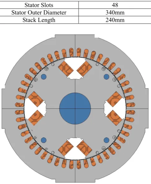
II. FEMODEL VERIFICATION AND SIMULATION RESULTS A commercial 48.5kVA SG, whose main specifications are given in Table 1, is studied in this paper and used as a platform to prove the concept. The machine, henceforth referred to as the production machine, is produced with a two-thirds short pitch winding, a stator skew of one slot pitch and a damper winding characterised by four bars-per-pole. A detailed 2D model of the production machine was built, shown in Fig. 1, and verified against test data. Skewing was achieved through the use of the multislice method and the damper bars were modelled as solid conductors to account for skin effect. The verification results are shown in Fig. 2.
TABLE 1
PARAMETERS OF STUDIED MACHINE
Parameter Value
Rated Power 48.5kVA
Rated Voltage 240V
Rated Frequency 50Hz
Rotor Type Salient Pole
Number of Poles 4
Power Quality Improvement by
Pre-Computed Modulated Field Current
for Synchronous Generators
Daniel Fallows, Stefano Nuzzo, Alessandro Costabeber, Michael Galea
Stator Slots 48
Stator Outer Diameter 340mm
[image:2.595.44.288.55.351.2]Stack Length 240mm
Fig. 1 - FE model of studied machine.
In order to highlight and emphasize the potential improvements possible by optimising the field current waveform, a downgrade of the above machine was implemented. The modified machine, henceforth referred to as the prototype machine, was developed with a full pitch winding, with no skewing of the core packs and with no rotor damper bars. A 2D model of the prototype machine was also built. The geometry and cross-sectional scheme of the modified machine are identical to that of the prototype machine as the only differences are those given above.
The two models (production and prototype machines) were then used to investigate the proposed methodologies as presented below.
A. Open-circuit characteristic
The FE model of the production machine was verified against experimental test data by open-circuit characterisation testing. Fig. 2 compares the open circuit characteristics of the production machine from both FE and experimental testing. Excellent similarity (between predicted and measured values) can be observed.
[image:2.595.314.547.57.198.2]The FE model of the production machine was modified to the specification of the prototype machine (full pitch winding, etc) and the open-circuit characterisation test carried out. From Fig. 2, the increased output of the prototype machine can also be observed. This is the result of the configuration changes described above (full pitch winding, etc). In particular the rated operating voltage (1 p.u.) was achieved with 13% less field current.
Fig. 2 - Open circuit characteristic comparison.
B. Voltage waveform at rated operating point
[image:2.595.312.550.339.471.2] [image:2.595.312.546.499.638.2]The general voltage waveform of the prototype machine model was captured, when operating at the DC field current so at to produce the rated voltage, as shown in Fig. 3. The harmonic components of this waveform, can be observed in Fig. 4, which shows that the 5th, 7th and slot (around 1.2 kHz) harmonics are significant, due to the combination of the full pitch layout, and the absence of skewing and damper cage effects.
Fig. 3 - Output waveform at rated field current.
Fig. 4 – Amplitude harmonic spectrum of the no-load output voltage at rated field current.
C. Considerations on the preliminary investigation
(partially) validated. In Fig. 3 it can be observed that the prototype machine, as expected, achieves a significantly higher output for a given field current at the expense of power quality. The aim of this paper is therefore to achieve the same (or improved) power quality as the production machine whilst maintaining the increased output benefits.
III. THE FIELD MODULATION CONCEPT A. Concept
It is well known that the voltage produced by a machine is equal to the rate-of-change of flux linkage, as governed by Faraday’s law. Therefore, in order to achieve a sinusoidal voltage output, the flux must also be sinusoidal. The following considerations are also very important to note:
The instantaneous flux linkage values for any given voltage waveform can be calculated for each point of rotation of a machine.
The instantaneous flux linkage is a product of the current flowing in the field windings, the rotor position and the number of turns on both the armature and field windings. The number of turns can be considered constants, thus the field current and the rotor position, can be considered as inputs for the expression given in (1).
= ( , ) (1)
For a given machine it is possible to create a two-dimensional matrix that gives the instantaneous field current required to produce a specific flux linkage at a particular rotor position.
The matrix can then be used as a lookup table to find the field current values for any chosen flux linkage waveform (and by extension voltage waveform). The resulting current waveform can be input to the field causing the machine to produce the chosen voltage waveform.
However, when applied to a real, practical machine there will be limitations to this method, including:
The inductance of the field winding preventing large, rapid changes in current;
Slip-rings or a rotor mounted power electronic converter required to supply the excitation;
The damper cage action smoothing changes in the field flux thereby cancelling the effects of the modulated field current.
This paper represents work focused on proving the concept described rather than addressing the real-world implementation. Some discussion will be made in response to this but fully addressing these challenges will be left to future work.
B. Production of Field Current Matrix
FE analysis was used to create the lookup matrix described in the previous section, as a matrix of flux linkage for each rotor position and field current. The use of FE analysis ensures that non-linear effects such as saturation and eddy currents are also taken into account. Interpolation functions have been developed and implemented in MATLAB to estimate the field
current value between flux linkage values for a given rotor position.
To populate the matrix a suite of transient simulations with motion representing the prototype machine operating at no-load condition have been carried out. The field current has been varied from 0A to 12A, in steps of 0.5A, while the time step has been set such that each step was equal to one third a degree of rotation. These procedures were done with the commercial package ANSYS Maxwell and the results post-processed with MATLAB.
1) Matrix Search and Interpolation Function
A function was created that loops through the flux linkage values for a given rotor position and locates the closest points to a given flux linkage value. The assumption is made that the flux linkage increases with field current, which is always true, except for when the flux linkage is close to zero.
The function carries out a linear interpolation between the points to return the required field current. A linear interpolation is not a true match but is acceptable given the density of the field current simulations (every 0.5A).
2) Creation of Improved Current Waveform
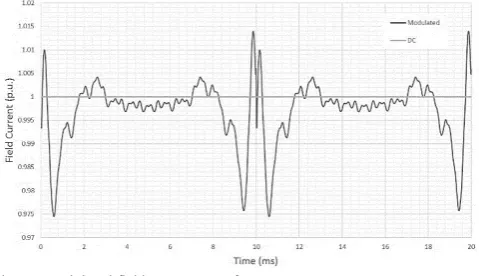
[image:3.595.310.550.404.542.2]The flux linkage values were calculated to give a sinusoidal output of 240V at 50Hz. These values were then input into the function to calculate the field current required at each angle of rotor rotation. Fig. 5 shows the field current waveform that was produced along with the nominal field current for the same operating point.
Fig. 5 - Modulated field current waveform.
In Fig. 5, it can be seen that there is a spike in the field current at each of the flux linkage zero crossing points due to the interpolation function assumption discussed in the previous section. This could be removed with further post-processing of the field current waveform.
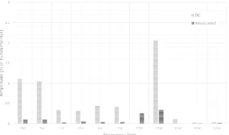
Fig. 6 - Frequency components of the modulated field current.
C. Simulation Results of Improved Field Waveform
In order to show the validity of the proposed method, the waveform shown in Fig. 5 was applied to the FE model of the prototype machine as a piecewise linear current source. The resulting output voltage waveform is shown in Fig. 7 with the original waveform for comparison. Fig. 8 shows a comparison between the harmonic contents of the two waveforms.
[image:4.595.306.554.70.148.2]An excellent improvement in terms of voltage waveform quality can be observed, particularly in the frequency components identified in Section II. A comparison in terms of THD is given in Table 2 showing that the modulated field prototype had a marked improvement over the production machine, which was the main objective of this work.
Fig. 7 - Comparison of output waveform with and without field modulation.
Fig. 8 - Comparison of output frequency content with and without field modulation.
TABLE 2
THDVALUES FOR EACH MACHINE
Machine THD (%)
Production (short pitch winding and
skewed stator) 1.46
Prototype (using DC field current) 3.90 Prototype (using modulated field current) 0.828
[image:4.595.311.546.285.421.2]Although the method showed significant room for improving the power quality of the 48.5kVA SG considered in this paper, a limitation of this method is the high field voltage required to produce a modulated field current. Fig. 9 shows a plot of the field voltage and confirms the levels required. The spikes present in the calculated field current waveform are behind the most significant voltage spikes. With further post-processing of this waveform it should be possible to limit the voltage requirements to 60V peak (the level at which the majority of the waveform already achieves).
Fig. 9 - Field voltage required to produce the modulated current waveform.
D. Performance of Field Modulation Under load
The required modulated field current waveform will change when the machine is placed on load. To maintain rated voltage the field current will have to increase which will push the iron into a different region of the saturation curve. Similarly the current flow in the armature winding will modify the air-gap flux thereby changing the harmonic content of the output voltage.
An in-depth study of field modulation as applied to a loaded machine is beyond the scope of this paper but will be investigated in future works.
E. Conclusions and Next Steps
This paper has demonstrated a simple and effective method to improve power quality in single-phase SGs. Use of this method in machines reduces manufacturing cost by easing the design and increases power density though the use of full pitched windings. The next step will be to verify the simulation results against a real machine under test. This will be achieved with a slip-ring excited machine and programmable signal generator. A future paper will detail the development of a rotating converter to replace the standard diode rectifier and provide the field modulation capability.
[image:4.595.50.286.388.522.2] [image:4.595.50.286.551.690.2]IV. REFERENCES
[1] Kostenko, M. and Piotrovsky, L., Electrical Machines. Vols. 1 and 2. Moscow: Mir, 1974.
[2] I. Boldea, Synchronous generators: The electric generators handbook. Boca Raton, FL: Taylor and Francis (CRC Press), 2005.
[3] J. Pyrhonen, T. Jokinen, V. Hrabovcova, and H. Niemel, Design of rotating electrical machines. Chichester, United Kingdom: Wiley, John & Sons, 2008.
[4] S. Nuzzo, M. Degano, M. Galea, C. Gerada, D. Gerada and N. Brown, "Improved Damper Cage Design for Salient-Pole Synchronous Generators," in IEEE Transactions on Industrial Electronics, vol. 64, no. 3, pp. 1958-1970, March 2017.
[5] C. Debruyne, J. Desmet, J. Rens and J. De Kock, "The effect of a reduced power quality on the energy efficiency of stand-alone generator systems," 2015 IEEE International Electric Machines & Drives Conference (IEMDC), Coeur d'Alene, ID, 2015, pp. 1902-1909. [6] M. T. Abolhassani, H. A. Toliyat and P. Enjeti, "An electromechanical
active harmonic filter," IEMDC 2001. IEEE International Electric Machines and Drives Conference (Cat. No.01EX485), Cambridge, MA, 2001, pp. 349-355.
[7] M. T. Abolhassani, H. A. Toliyat and P. Enjeti, "Harmonic compensation using advanced electric machines," Industrial Electronics Society, 2001. IECON '01. The 27th Annual Conference of the IEEE, Denver, CO, 2001, pp. 1388-1393 vol.2.
Available: http://home.process.com/ Intranets/wp2.htp
[8] M. L. M. Kimpara, J. O. P. Pinto, B. Fahimi, P. E. M. J. Ribeiro, R. B. Godoy and L. E. B. Silva, "Field reconstruction method applied for harmonic voltage mitigation in salient pole synchronous generators," 2013 Brazilian Power Electronics Conference, Gramado, 2013, pp. 890-895.
V. BIOGRAPHIES
Daniel Fallows graduated in 2015 with a Masters in Engineering from the University of Nottingham, UK, and was awarded the IET Prize 2015. Currently he is a PhD student within the PEMC group at the University of Nottingham. His employment experience includes working at Cummins
Generator Technologies where he was involved with engineering software development and synchronous machine analysis. His special fields of interest include synchronous generator excitation systems and embedded computing.
Stefano Nuzzo received his B.Sc. and M.Sc. degrees in Electrical Engineering from the University of Pisa, Pisa, Italy, in 2011 and 2014, respectively. He is currently a Ph.D. student with the Power Electronics, Machines and Control Group, The University of Nottingham, Nottingham, U.K. He spent six months with The University of Nottingham as a Visiting Student in 2013, where he was involved in developing analytical and numerical models for the analysis of permanent magnet synchronous machines. His current research interests include the analysis and design of salient-pole synchronous generators and brushless excitation systems.
Alessandro Costabeber received the M.S. degree with honours in electronic engineering from the University of Padova, Padova, Italy, in 2008 and the Ph.D. degree from the same university in 2012, on energy efficient architectures and control techniques for residential microgrids. In 2014 he joined the PEMC group, Department of Electrical and Electronic Engineering, University of Nottingham, Nottingham, UK as Lecturer in Power Electronics. His current research interests include HVDC converters topologies, high power density converters for aerospace applications, control solutions and stability analysis of AC and DC microgrids, control and modelling of power converters, power electronics and control for distributed and renewable energy sources. Dr. Costabeber received the IEEE Joseph John Suozzi INTELEC Fellowship Award in Power Electronics in 2011.