Journal Name
Cite this: DOI: 10.1039/c0xx00000x
www.rsc.org/xxxxxx
Dynamic Article Links
►
ARTICLE TYPE
Development and performance of MgFeCrO
4
– based electrodes for
solid oxide fuel cells
Elena Stefan,*
aPaul A. Connor
aand John T.S. Irvine*
aReceived (in XXX, XXX) Xth XXXXXXXXX 20XX, Accepted Xth XXXXXXXXX 20XX
DOI: 10.1039/b000000x 5
Abstract
Composite anodes for solid oxide fuel cells (SOFC) developed on yttria stabilised zirconia (YSZ) porous supports by infiltration of electrode materials has been successfully applied for various anode and cathode compositions, resulting in high performance SOFC devices. The focus of this study is the performance of the chromium-rich spinel (MgFeCrO4) as an electrode support material when used alone or impregnated.
10
The composite anodes were prepared by aqueous infiltration of nitrate salts to produce
(La0.75Sr0.25)0.97Cr0.5Mn0.5O3-δ, Ce0.9Gd0.1O2-δ, CeO2 or Pd into a MgFeCrO4 scaffold with 45% porosity
and studied by electrochemical impedance spectroscopy in symmetrical cell configuration. The
performance was evaluated in humidified 5%H2/Ar in order to quantify their stability and performance up
to 850 C with respect to the MgFeCrO4 porous substrate. It was found that all the impregnated phases
15
adhere very well to the spinel and considerably enhance performance and stability to a level required for SOFC applications. MgFeCrO4/LSCM/CGO and MgFeCrO4/LSCM/CGO/Pd showed the most
substantial improvement in comparison to the scaffolds performance, with ASR values of 1.74 Ωcm2 and
0.91Ωcm2, respectively.
1.
Introduction
20SOFCs are electrochemical devices which convert chemical energy stored in a fuel into electricity, via an electrochemical reaction at elevated temperatures (600-1000 °C).1,2 The
development of fuel cell technology is encouraged by the clean production of electricity from a variety of fuels without the
25
combustion step resulting in higher conversion efficiency and with low emissions of pollutants.3–6 However, for superior
electrochemical performance, the material requirements for such devices are rather demanding and lead to expensive materials. The material requirements along with the tendency of decreasing
30
the functioning temperatures for SOFCs encourage the development of new materials.
Thus, the application of ferritic stainless steels as interconnect materials in SOFCs is a desirable option for decreasing materials costs. These steels have several disadvantages when used in fuel
35
cells, mainly chromium poisoning of electrodes and high temperature oxidation to form oxide scales such as chromia and (Mn,Fe,Cr)3O4 or (Mn,Cr)3O4 spinels.7–12 . The compatibility of
the interconnect with the electrode material is directly connected to their interface, where usually the materials may react, leading
40
to performance degradation. Employing chromium-spinels at the interconnect/electrode interface might improve the compatibility as a transition layer between the metal and the electrode oxide materials. The interface interconnect/electrode is poorly optimised in a stack (optimisation of physical and chemical
45
nature), leading to much lower performance of the stacked fuel cells than individually tested cells.16 The use as a support material
of a low cost, redox stable oxide that is compatible with high temperature steels, various electrode materials and YSZ would be of significant value.
50
We previously reported that several chromium-rich spinels displayed promising chemical stability and electrical conductivity in reducing conditions,17 leading us to investigate MgFeCrO
4 as
an anode support material. Spinel MgFeCrO4 has a chemical
composition and crystal structure closely related to the oxide
55
scale formed on interconnect surfaces following oxidation of ferritic steels (FeCr alloy). However these materials would not be expected to be good electrodes, without the addition of extra materials to form composite electrodes. LSCM has been previously studied and reported as an efficient stable electrode
60
material in reducing and oxidizing conditions and enhances the electronic conductivity in composite anodes.18–21 Ionic
conductivity is another desirable property for electrode materials, or composite electrodes so ionic conducting materials as CGO or CeO2 22 can be added to improve the total performance of the
65
cells. Pd is a well known catalyst to promote electrochemical reactions.23
Therefore the aims of this study were to fabricate MgFeCrO4
scaffolds and to evaluate the electrochemical performance of
70
symmetrical cells based on such scaffold impregnated with electrode materials (La0.75Sr0.25)0.97Cr0.5Mn0.5O3-δ (LSCM),
2 | Journal Name, [year], [vol], 00–00 This journal is © The Royal Society of Chemistry [year]
2.
Experimental
Symmetrical cells were produced by tape casting the MgFeCrO4
electrode material with the YSZ electrolyte layer screen-printed on the green (un-sintered) tapes. The final structures were obtained by laminating two green MgFeCrO4/YSZ tapes. Green
5
MgFeCrO4 ceramic tapes were obtained by tape casting a slurry
containing spinel powder, organic binder (poly(vinyl-butyrate)), dispersant (dibutyl(phthalate)), plasticiser (poly(ethylene-glycol)) and graphite pore former (~6 wt.% - of total solids). MgFeCrO4
was obtained by combustion synthesis and the experimental
10
description is covered in our previous work.17 Laminated green
tapes were sintered at 1400 °C for 12 h. In the final ceramic structure the 25 μm thick dense electrolyte was enclosed between two porous spinel layers with 45% porosity and 200 μm
thickness. The relative density of the sintered scaffold was
15
determined from the measured diameter and thickness (from SEM micrograph), with the electrolyte weight, as estimated from sintering studies of different structures, subtracted from that of the sintered body.
The porous layers were used as scaffolds for LSCM, with
20
additions of CGO, CeO2 and Pd, which were impregnated into the
supports as nitrate solutions prepared with the reagents: La(NO3)3∙6H2O Alfa Aesar (>99.99%), Sr(NO3)2 Sigma Aldrich
(>99%), Cr(NO3)3∙9H2O Sigma Aldrich (99.5%),
Mn(NO3)2∙4H2O Alfa Aesar (99.98%), Ce(NO3)3∙6H2O Aldrich
25
(99%), Gd(NO3)3∙6H2O Aldrich (99.9%). The desired loadings of
electrode and catalyst material were obtained with the impregnation carried out as a multistep process, with intermediary calcinations steps at 500°C and final sintering steps at 1200 °C (4 h) for LSCM, 1000 °C (4 h) for CGO and 450 °C
30
(1 h) for CeO2 and Pd. The electrodes prepared in this study, with
[image:2.595.302.541.446.580.2]the specific component loadings, in wt. % are labelled as presented in Table 1.
Table 1.Composite electrodes prepared in this study by impregnating porous MgFeCrO4 scaffolds and the nomenclature used for them 35
throughout this paper.
Composition (wt. %) Label
Support (MgFeCrO4) MgFeCrO4
+ LSCM (31%) MgFeCrO4/LSCM
+ LSCM (27%) / CGO (15%) MgFeCrO4/LSCM/CGO
+ LSCM (27%) / CeO2 (6%) MgFeCrO4/LSCM/CeO2
+ LSCM (27%) / CGO (15%) / Pd(1%) MgFeCrO4/LSCM/CGO/Pd
+ LSCM (27%) / CeO2 (6%) / Pd (1%) MgFeCrO4/LSCM/CeO2/Pd
MgFeCrO4/LSCM/CGO and MgFeCrO4/LSCM/CeO2 were
prepared by sequential impregnation of materials in order of decreasing required sintering temperature. The formation of
40
perovskite phase inside the scaffolds was confirmed by X-ray diffraction.
Phase analysis for symmetrical cells was performed on a PANalytical Empyrean Diffractometer in reflection mode, while microstructure was observed on a JEOL JSM-6700F Scanning
45
Electron Microscope (SEM).
Electrochemical performance was determined by electrochemical impedance spectroscopy (EIS) in the frequency range of 1 MHz-0.1 Hz with 20 mV AC perturbation amplitude using a Solartron 1260 frequency response analyser and SMaRT v2.8.0
50
(Solartron Analytical) and ZView v3.1c software (Scribner
Associates). The geometric area of symmetrical cell electrodes was 1.2 cm2 on either side of the dense electrolyte layer.
Measurements were made in a single chamber, consisting of a quartz tube with one open end in which a two electrode alumina
55
testing jig was inserted and closed gas tight. The alumina jig had inlet and outlet for gas flow (humidified (3%H2O) 5%H2/Ar) and
platinum wires for electrical contact to the sample and a sample thermocouple. Measurements included temperature dependence and assessment of the reduction process at a constant temperature
60
of 850 °C. The ohmic resistance of the testing jig and constituent Pt wires was measured and subtracted from the results obtained for symmetrical cells. In order to remove the contribution of the thin YSZ electrolyte layer in the series resistance (Rs), a pellet of
YSZ was measured by AC impedance and the resistance of the
65
electrolyte layer was calculated and subtracted from the Rs value.
3.
Results and discussion
3.1 Phase analysis and microstructure of MgFeCrO4 scaffold The requirements for the application of MgFeCrO4 as electrode
70
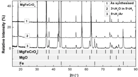
support on the fuel side of SOFCs comprise chemical and microstructural stability of the spinel under reducing conditions. We assessed the chemical stability of MgFeCrO4 in dry and
humidified 5%H2/Ar at 1000 °C for 20 h. When reduced in dry
5%H2/Ar, the MgFeCrO4 decomposed, with segregation of
75
metallic Fe and MgO The material reduced in humidified 5%H2/Ar did not decompose, as the partial pressure of oxygen
(pO2) was above the stability limit for which secondary phases did not segregate from the spinel (Fig. 1). When reduced at 850 °C for 30 h in dry 5%H2/Ar the MgFeCrO4 showed no sign of
80
decomposition, which indicates stability in fuel environments when operated lower than 850 °C.
Fig. 1X-ray diffraction pattern of MgFeCrO4 scaffold reduced in dry 85
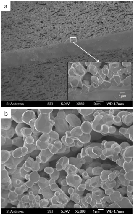
Fig. 2 Micrograph of MgFeCrO4 / YSZ / MgFeCrO4 scaffold, with detail
of the spinel/YSZ interface and the spinel porous layer.
In Fig. 2 are illustrated SEM images in cross-section of the
5
MgFeCrO4 scaffold, with a general overview of the symmetrical
architecture, the thickness of the YSZ electrolyte and the interface formed between YSZ and spinel. Sintered ceramic bodies were not cracked or curved after sintering, thus affirming that any difference in thermal expansion coefficient is small
10
enough to not cause any significant mechanical damage. The spinel had particle size 1-5 µm, good connectivity and open porosity for loading other materials by impregnation.
3.2 DC conductivity of MgFeCrO4 scaffold 15
DC conductivity was measured at 850°C on a 63% dense pellet switching from static air to humidified 5%H2/Ar (log pO2 ~ -18).
The conductivity increased significantly from 0.014 Scm-1 to
0.36 Scm-1 upon this reduction, indicating the n-type behaviour
for the material, as illustrated in Fig. 3.
20
Fig. 3. DC electrical conductivity of a 63% dense MgFeCrO4 pellet
plotted as a function of time in reducing conditions at 850 °C. The inner plot shows the same data as a function of pO2.
3.3 Phase analysis and microstructure of impregnated 25
MgFeCrO4 scaffolds
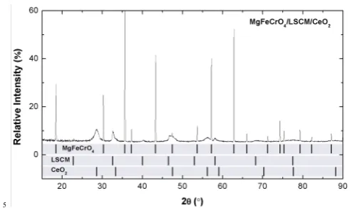
XRD patterns corresponding to MgFeCrO4/LSCM and
MgFeCrO4/LSCM/CGO are presented in Fig. 4 and the patterns
for MgFeCrO4/LSCM/CeO2 in Fig. 5. All the peaks observed in
the XRD patterns correspond to phases present in the samples:
30
spinel and perovskite or spinel, perovskite and CGO, or CeO2
respectively. The XRD pattern for MgFeCrO4/LSCM/CeO2 (Fig.
5) showed broad peaks corresponding to CeO2 which is an
indication that the Cerium nitrate has decomposed with the formation of CeO2 with very small particle size.
35
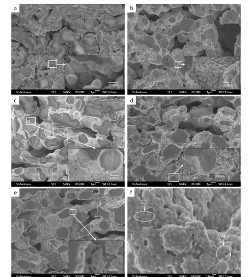
In Fig. 6 cross-sectional SEM images from samples tested in humidified 5%H2/Ar are presented. Cross-sectional SEM images
confirm that infiltrated phases have good adherence and coverage to the scaffold, while images from the surface show mostly the microstructure of the infiltrated phases. In Fig. 6a, the micrograph
40
for MgFeCrO4/LSCM showed LSCM particles (500 nm – 1 µm)
that adhere well to the spinel particles. MgFeCrO4/LSCM/CeO2
(Fig. 6b) had a microstructure similar to MgFeCrO4/LSCM
samples and ceria nano-particles could be observed. The micrograph of MgFeCrO4/LSCM/CGO (Fig. 6c) confirmed that
45
additional thermal treatments at 1000 °C following the infiltration of CGO, led to densification of LSCM layer, while CGO particles of size 0.1-0.5 µm were apparently very well connected to the LSCM layer. For MgFeCrO4/LSCM/CeO2/Pd sample, CeO2 and
the assumed to be Pd nano-particles could be observed on the
50
LSCM layer. In Fig. 6e,f is illustrated the microstructure of MgFeCrO4/LSCM/CGO/Pd in cross section (e) and surface (f)
suggesting the presence of Pd nanoparticles with size ~10-20 nm on top of larger particles of CGO. Pd nanoparticles are expected to behave as electrocatalytic sites during symmetrical cell
55
[image:3.595.313.550.47.231.2] [image:3.595.61.288.52.413.2]4 | Journal Name, [year], [vol], 00–00 This journal is © The Royal Society of Chemistry [year]
Fig. 4 X-ray diffraction pattern of MgFeCrO4/LSCM and
MgFeCrO4/LSCM/CGO with LSCM sintered at 1200 °C (4 h) and CGO
at 1000 °C (4 h).
5
Fig. 5 X-ray diffraction pattern of MgFeCrO4/LSCM/CeO2 with LSCM
[image:4.595.296.542.48.194.2]Journal Name
Cite this: DOI: 10.1039/c0xx00000x
www.rsc.org/xxxxxx
Dynamic Article Links
►
ARTICLE TYPE
Fig. 6 SEM images in cross-section of: (a) MgFeCrO4/LSCM; (b) MgFeCrO4/LSCM/CeO2; (c) MgFeCrO4/LSCM/CGO; (d) MgFeCrO4/LSCM/CeO2/Pd;
(e) MgFeCrO4/LSCM/CGO/Pd; (f) surface micrograph for MgFeCrO4/LSCM/CGO/Pd - Pd particles . The micrographs were collected after the samples 5
[image:5.595.55.545.121.666.2]Journal Name
Cite this: DOI: 10.1039/c0xx00000x
www.rsc.org/xxxxxx
Dynamic Article Links
►
ARTICLE TYPE
This journal is © The Royal Society of Chemistry [year] [journal], [year], [vol], 00–00 | 6 3.4 Electrochemical performance of impregnated MgfeCrO4
scaffolds
The electrochemical performance of the impregnated scaffolds measured in 5%H2/Ar suggests their suitability as SOFC anodes,
for realistic, fully humidified fuels. Comparative impedance
5
spectra for the symmetrical cells at 850 °C in humidified 5%H2/Ar are displayed as Nyquist and Bode plots in Fig. 7a,b.
Results obtained by fitting the experimental data to the equivalent circuit illustrated in Fig. 8, are summarised in Table 2. The temperature dependence of ohmic resistances (Rs) and
10
polarisation resistances (Rp) values are shown in Fig. 7c,d as
Arrhenius plots. The ohmic resistance of the scaffold had a significantly lower value (Rs=0.47 Ωcm2), in comparison with the
other impregnated samples (Table 2). The Rs value increased with
the infiltration of various phases, and the most for
15
MgFeCrO4/LSCM. Even after reduction the Rs value of
MgFeCrO4/LSCM remained the highest amongst the tested
samples, 4.65 Ωcm2. This may have been caused by two different
contributions: first, the efficient reduction of the MgFeCrO4
scaffold was observed to have a major impact for the ohmic
20
resistance, thus when infiltrated into the non-reduced scaffold, LSCM had a good adherence to the spinel particles and hindered the efficient reduction of the scaffold. Secondly, LSCM has p-type conductivity and in reducing atmosphere, its electronic conductivity decreases,18,24 thus its contribution led to an increase
25
of the the ohmic resistance. However, the infiltration of LSCM into the scaffold had a positive effect for the Rp value, as its
electrochemical properties are superior to the spinel. The addition of CeO2 or CGO further improved the cell performances, with
both Rs and Rp decreasing. Rs values for MgFeCrO4/LSCM/CGO
30
and MgFeCrO4/LSCM/CeO2 were about the same, while Rp
values seemed to decrease in proportion to the quantity of ionic conducting material impregnated into the sample. MgFeCrO4/LSCM/CGO/Pd and MgFeCrO4/LSCM/CeO2/Pd
showed even better performance in Rs and Rp, as presented in Fig.
35
7a. Thus, the addition of catalysts contributed positively to the electrochemical tests, presumably by facilitating surface exchange reaction which is the initial step in the reduction of the scaffold. The reduced surface layer resulted in formation of a conduction path with increased conductivity.
Journal Name
Cite this: DOI: 10.1039/c0xx00000x
www.rsc.org/xxxxxx
Dynamic Article Links
►
ARTICLE TYPE
Fig. 7 Symmetrical cells measured in humidified 5%H2/Ar at 850 °C: (a) Nyquist plot containing data for the whole cell (two equal electrodes); (b) Bode
plot of phase angle vs. frequency; (c), (d), (e), (f) Arrhenius plots for Rs, Rp Rp1 and Rp2 resulted from equivalent circuit fitting of experimental data. The 5
[image:7.595.112.495.120.685.2]Journal Name
Cite this: DOI: 10.1039/c0xx00000x
www.rsc.org/xxxxxx
Dynamic Article Links
►
ARTICLE TYPE
[image:8.595.43.543.164.295.2]This journal is © The Royal Society of Chemistry [year] [journal], [year], [vol], 00–00 | 8
Table 2. Relaxation frequencies and polarisation resistances for symmetrical cells tested in humidified 5%H2/Ar at ~850 °C. Rs and Rp (Rp1, Rp2) are
determined from equivalent circuits fitting and listed values are for one electrode.
Electrode Rs(Ωcm2) Rp(Ωcm2) fmax1 (Hz) Process 1 fmax2 (Hz) Process 2 Rp1(Ωcm2) Rp2(Ωcm2)
MgFeCrO4 0.47 5.09 1200 Charge transfer 132 Dissociative gas adsorption 0.80 4.29
MgFeCrO4/LSCM 4.65 2.66 5250 Charge transfer 190 Dissociative gas adsorption 1.68 0.98
MgFeCrO4/LSCM/CGO 3.20 1.74 6310 Charge transfer 76 Dissociative gas adsorption 1.25 0.48
MgFeCrO4/LSCM/CeO2 2.92 3.19 5250 Charge transfer 30 Dissociative gas adsorption 2.23 0.96
MgFeCrO4/LSCM/CGO/Pd 1.33 0.91 3020 Charge transfer 63 Dissociative gas adsorption 0.56 0.35
MgFeCrO4/LSCM/CeO2/Pd 2.10 2.68 3630 Charge transfer 63 Dissociative gas adsorption 1.60 1.10
5
Fig. 8 Equivalent circuit used to fit experimental data, where L=inductor; Rs=series resistance; Rp=polarisation resistance and CPE=constant phase
element.
Impedance spectra showed two arcs, one process distinguishable at high frequency and one process at low frequency. The presence
10
of two semicircles was observable for all the impregnated samples, while the scaffold showed a single bigger and depressed arc. The high frequency arc was always the largest and both processes were changing for different catalysts infiltrated into scaffolds. The attribution of processes is based on relaxation
15
frequency,25–27 which in this study were determined from
equivalent circuits fitted to Bode plots (-Z"vs.f). The high frequency process corresponds to charge transfer and the low frequency process could be attributed to gas adsorption/desorption or association/dissociation. MgFeCrO4 is
20
not expected to be an ionic conductor, thus the high frequency process with fmax1=1200 Hz corresponds to electronic transfer,
while the low frequency process with fmax2=132 Hz, is most likely
gas adsorption/desorption. Relaxation frequencies determined for MgFeCrO4/LSCM had similar magnitudes to the scaffold ones,
25
5250 Hz for high frequency process and 190 Hz at low frequency, corresponding probably to the same processes as previously described, charge transfer, at high frequency and gas adsorption/desorption, at low frequency. Table 2 summarizes relaxation frequencies, the associated processes at high and low
30
frequency and Rp1 and Rp2 values corresponding to each process.
Scaffolds infiltrated with different materials showed the same trend, the resistance was higher for charge transfer than for gas adsorption/desorption and association/dissociation, while the uninfiltrated scaffold showed higher resistance for gas kinetic
35
processes than for charge transfer. Activation energies (Ea) for Rs
and Rp are included in Fig. 7c,d, where Ea for Rs is related to the
conduction activation and Ea for Rp is related to the
electrochemical processes described by the impedance spectra in Fig. 7a. The Ea with regard to Rs (0.35 eV) for
40
MgFeCrO4/LSCM was smaller than Ea value of 0.56 eV
measured for LSCM in 5%H2/Ar18 and the Ea value 0.43 eV
determined for the scaffold. Ea values for Rs generally remained
below 0.51 eV, value that corresponded to
MgFeCrO4/LSCM/CGO and MgFeCrO4/LSCM/CeO2. In air, the
45
reported Ea values for CGO are 0.60 eV28 and 0.64 eV29, for
which the conductivity is mostly ionic. However, in reducing conditions mixed ionic-electronic conductivity may arise due to the reduction of Ce4+ to Ce3+. The conductivity mechanism for
the electrons is considered to be small polaron activated hopping
50
process which implies low mobility.29 These contributions
explain to certain extent, the increase in Ea with CGO and CeO2
infiltration. The Ea values for Rp showed an increase from the
scaffold (0.25 eV) to the composite electrodes, with a maximum value of 0.45 eV observed for MgFeCrO4/LSCM/CGO/Pd. As
55
illustrated in Fig. 7e,f, the activation energies for Rp1 and Rp2
components of the Rp values indicate that the charge transfer
process is more temperature dependent and has a larger resistance than the gas adsorption process.
The best achieved electrochemical performance was for
60
MgFeCrO4/LSCM/CGO/Pd, which was comparable to results
reported for LSCM used as an SOFC anode material. In humidified 5%H2/Ar at 850°C, Rp of 0.59 Ωcm2 has been
observed,18,20 while at 900 °C R
pvalues of 0.51 Ωcm2 (ref 18) and
0.43 Ωcm2 (ref 20) have been measured. In humidified H 2 at
65
900 °C, D.M Bastidas et al19 reported an R
pof 0.3 Ωcm2, while
S.P. Jiang et al30 reported R
p values for a 1:1 composite
LSCM-YSZ, with LSCM obtained by gel-casting or solid state reaction
of 1.1 Ωcm2and 1.9 Ωcm2, respectively. The comparable results
obtained here relative to results reported in the literature are
70
encouraging since the MgFeCrO4 scaffold is not ionically
conducting and since the amount of loaded perovskite was limited. Furthermore, Ea values for Rp included in Fig. 7d were
lower than Ea values of between 0.70-0.90 eV reported by S.P.
Jiang et al30 for LSCM/YSZ composite anodes.
3.5 Influence of prolonged reduction of impregnated MgFeCrO4 scaffold upon electrochemical performance
The electrochemical performance of the symmetrical cells after prolonged exposure to humidified 5%H2/Ar is relevant for
5
evaluating the stability of the tested SOFC anodes. The reduction
process was performed on symmetrical cells heated to ~850 °C in humidified 5%H2/Ar. Once constant temperature was reached,
impedance measurements were taken after 1 h and 11 h. Nyquist plots for measurements after 1 h and 11 h are compared in Fig.
10
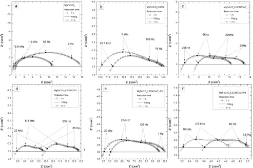
[image:9.595.57.551.137.465.2]9a-f, to estimate the influence of reduction upon tested scaffolds infiltrated with different catalysts.
Fig. 9 Nyquist plots for the samples reduced at 850 °C for 1 h/11 h and the corresponding equivalent circuit fit; spectra contain data for 2 identical
15
electrodes.
The performance of the cells improved with increasing reducing time consistently: for MgFeCrO4 the reduction had a significant
contribution in decreasing the Rp value (3.26 Ωcm2), decrease in
20
resistance that corresponded to the low frequency process, possibly due to improvements in the gas surface exchange kinetics after reduction. MgFeCrO4/LSCM showed a decrease in
Rs and an increase in Rp corresponding to an increase in
resistance of both high and low frequency processes: 0.12 Ωcm2
25
for Rp1 and 0.21 Ωcm2 for Rp2. MgFeCrO4/LSCM/CeO2 had a
small decrease of Rp and an important decrease of Rs of about
0.55 Ωcm2 after 11 h of reduction. Reduction of
MgFeCrO4/LSCM/CGO showed a significant improvement in Rs
(~1 Ωcm2 decrease) and R
p (~0.22 Ωcm2 decrease in Rp1 and
30
~0.08 Ωcm2 decrease in R
p2). MgFeCrO4/LSCM/CeO2/Pd and
MgFeCrO4/LSCM/CGO/Pd had similar improvement in the cells
performance after reduction with a decrease of Rs values
(~0.3 Ωcm2), while R
p did not change. The values reported above
are for one electrode. The reduction in Rs and Rp could be
35
attributed mostly to the reduction of the support material. Only
MgFeCrO4/LSCM showed an increase in Rp that could be
explained by the p-type semiconductor behaviour of the LSCM, with the reduction of its conductivity in 5%H2/Ar.31 The
reduction process had positive effects for cell performance and
40
this contribution was more important than the negative effect corresponding to sintering of ceria nano-particles,32 a process that
cannot be noticed here.
The modelled data are in a good agreement with the measured points indicating a good fit of the equivalent circuit with the
45
electrochemical processes identified for the samples.
4.
Conclusions
Porous scaffolds of MgFeCrO4 were prepared in symmetrical
configuration by combining tape casting and screen printing techniques. MgFeCrO4 was stable when reduced in dry 5%H2/Ar,
50
at 850 °C and in humidified 5%H2/Ar, at 1000 °C. Thus, the
10 | Journal Name, [year], [vol], 00–00 This journal is © The Royal Society of Chemistry [year] fuel cells, direct carbon fuel cells etc.)
In terms of chemical stability, the results presented above suggest that there is no or limited reactivity between MgFeCrO4 and other
cell materials. MgFeCrO4 had satisfactory performance as anode
electrode support, as the infiltrated materials had a good
5
adherence to the spinel particles. The formed coating diminished the scaffolds reduction, thus leading to an increase in Rs for tested
samples. However, the insertion of electrode materials into the scaffolds decreased polarisation resistances of the cells, as it formed a new conducting path and their electrochemical activity
10
was superior to the spinel. Further catalyst insertion facilitated the reduction of the scaffold and, as expected, enhanced the performance of symmetrical cell as new electrocatalytic sites were active during electrochemical tests. The reduction process had a positive influence for the symmetrical cells performance
15
even if hindered by infiltrated electrode materials. Overall, both reduction process and increase of electrocatalytic activity determined improvements in the electrochemical performance.
Acknowledgements
20The authors thank the Office of Naval Research, USA, grant code N00014-11-1-0247, the Engineering and Physical Sciences Research Council, UK, grant platform EP/E064248/1 and the European Union’s Seventh Framework Programme (FP7/2007-2013) for the Fuel Cell and Hydrogen Joint Technology initiative
25
under grant agreement n°[FCH JU-GA 278257]10 for financial support.
Notes and references
a School of Chemistry, University of St. Andrews, Fife KY16 9ST, U.K.
E-mail: [email protected]; [email protected] 30
1. J. W. Fergus, Int. J. Hydrogen Energ., 2007, 32, 3664 – 3671.
2. M. Gödickemeier, Mixed ionic electronic conductors for solid oxide fuel cells, [Mikrofiche-Ausg.]., 1996.
35
3. International Energy Outlook 2011, U.S. Energy Information
Administration, 2011.
4. A. Galich and L. Marz, Energy, Sustainability and Society, 2012, 2, 2. 5. A. Atkinson, S. Barnett, R. J. Gorte, J. T. S. Irvine, A. J. McEvoy, M. Mogensen, S. C. Singhal, and J. Vohs, Nat. Mater., 2004, 3, 17–27.
40
6. W. Z. Zhu and S. C. Deevi, Mat Sci Eng A, 2003, 362, 228 – 239. 7. F. H. Stott, F. I. Wei, and C. A. Enahoro, Materials and Corrosion, 2004,
40, 198–205.
8. Horita, K. Yamaji, Y. P. Xiong, H. Kishimoto, N. Sakai, and H. Yokokawa, Solid State Ionics, 2004, 175, 157–163.
45
9. Fergus, Int. Mater. Rev., 2005, 397, 271–283.
10. F. Tietz and D. Sebold, Materials science & engineering. B, Solid-state
materials for advanced technology, 150, 135–140.
11. L. Cooper, S. Benhaddad, A. Wood, and D. G. Ivey, J Power Sources, 2008, 184, 220–228.
50
12. Larring and T. Norby, Journal of the Electrochemical Society, 2000, 147, 3251–3256.
13. X. Chen, P. Hou, C. Jacobson, S. Visco, and L. Dejonghe, Solid State Ionics, 2005, 176, 425–433.
14. Z. Yang, G. Xia, X. Li, and J. Stevenson, 55 International Journal of
Hydrogen Energy, 2007, 32, 3648–3654.
15. Z. Yang, G.-G. Xia, C.-M. Wang, Z. Nie, J. Templeton, J. W. Stevenson, and P. Singh, J Power Sources, 2008, 183, 660–667.
16. S. C. Singhal, in Solid Oxide Fuels Cells: Facts and Figures, eds. J. T. S. Irvine and P. Connor, Springer London, 2013, pp. 1–23.
60
17. E. Stefan and J. Irvine, Journal of Materials Science, 2011, 46, 7191– 7197.
18. S. Tao and J. T. S. Irvine, Nat. Mater., 2003, 2, 320–323.
19. D. M. Bastidas, S. Tao, and J. T. S. Irvine, J. Mater. Chem., 2006, 16, 1603–1605.
65
20. J. C. Ruiz-Morales, J. Canales-Vázquez, J. Peña-Martínez, D. Marrero-López, and P. Núñez, Electrochim. Acta, 52, 278–284.
21. X. Yang and J. T. S. Irvine, J Mater Chem, 2008, 18, 2349–2354. 22. M. Mogensen, N. M. Sammes, and G. A. Tompsett, Solid State Ionics,
2000, 129, 63 – 94.
70
23. J. H. Kim, D. Miller, H. Schlegl, D. McGrouther, and J. T. S. Irvine,
Chem. Mater., 2011, 23, 3841–3847.
24. G. Kim, G. Corre, J. T. S. Irvine, J. M. Vohs, and R. J. Gorte,
Electrochem. Solid St., 11.
25. M. J. Jørgensen and M. Mogensen, 75 J. Electrochem. Soc., 148, A433– A442.
26. T. Ramos, J. Hjelm, and M. Mogensen, J. Electrochem. Soc., 158. 27. I. M. Torres da Silva, J. Nielsen, J. Hjelm, and M. Mogensen, ECS
Transactions, 2009, 25, 489–498.
28. C. Xia and M. Liu, 80 Solid State Ionics, 2002, 152–153, 423–430. 29. B. C. H. Steele, Solid State Ionics, 2000, 129, 95–110.
30. S. P. Jiang, L. Zhang, and Y. Zhang, J. Mater. Chem., 2007, 17, 2627– 2635.
31. S. Tao and J. T. S. Irvine, J. Electrochem. Soc., 2004, 151, A252–A259. 32. M. Gross, J. Vohs, and R. Gorte, 85 J. Electrochem. Soc., 2007, 154, B694–