Modeling and Simulations of Experimentally-Observed Dislocation Substructures
Based on Field Theory of Multiscale Plasticity (FTMP) Combined with TEM
and EBSD-Wilkinson Method for FCC and BCC Poly
/
Single Crystals
T. Hasebe
1,+, M. Sugiyama
2, H. Adachi
3, S. Fukutani
4and M. Iida
4 1Department of Mechanical Engineering, Kobe University, Kobe 657-8501, Japan2Advanced Technology Research Laboratories, Nippon Steel & Simitomo Metal Corporation, Futtsu 293-8511, Japan 3Department of Mechanical Engineering, Kagoshima University, Kagoshima 890-8580, Japan
4Graduate School of Engineering, Kobe University, Kobe 657-8501, Japan
An attempt is made here to reproduce the experimentally-observed inhomogeneous deformation structures based on FTMP (Field Theory of Multiscale Plasticity), where TEM observations for sheared single crystal samples with four typical crystallographic orientations as well as an EBSD-Wilkinson method-based result for a polycrystal are taken as recent successful examples, ultimately aiming at developing a new technique for in situ/ex situ local-global inhomogeneity evaluation during elasto-plastic deformation combined with these experimental techniques. Crystal plasticity-basedfinite element simulations utilizing FTMP-based incompatibility model are conducted in connection with a working hypothesis calledflow-evolutionary law, whose manifestation is given as a relationship between the incompatibility tensor and the energy-momentum tensor (duality diagram). Demonstrated are not only successful reproductions of the orientation-dependent dislocation substructures and the intra-granularly evolved deformation structures, but also the associated energyflow with the evolved inhomogeneities visualized on the corresponding duality diagram. [doi:10.2320/matertrans.M2013226]
(Received June 14, 2013; Accepted February 13, 2014; Published April 11, 2014)
Keywords: multiscale plasticity, crystal plasticity, dislocation substructure, transmission electron microscopy (TEM), electron backscatter diffraction (EBSD)-Wilkinson method,field theory
1. Introduction
Critical significance of dislocation substructures evolving during elasto-plastic deformation within metallic crystalline materials for controlling their mechanical responses has been gradually but steadily recognized, in conjunction with recent rapid advancements of measurement and observation tech-niques. A number of empirical observations strongly and eloquently imply the critical significance of these evolving dislocation substructures (observable solely via TEM, so far) that directly/indirectly controls the mechanical properties of the targeted materials. Differences in their morphologies can lead to distinctions in the macroscopic stress responses. Simultaneously, a drastic advancement in multiscale theoret-ical concept and the associated modeling schemes has been achieved rather exclusively.19) This study is, as it were, a milestone resulted from dynamic interactions of the two up-to-date streams for the purpose of tacking the unsolved complex problems about multiscale materials engineering.
Myriads of multiscale approaches have been attempted to model complex phenomena, such as those based onab initio, molecular dynamics (MD), dislocation dynamics (DD), quasicontinuum (QC), homogenization method, and variation of a sort of extended crystal plasticity. An overview of the conventional kinds of theories and schemes can be found in literature,10)but the importance of evolutionary aspects of the above-mentioned substructures has not been so emphasized in recognizing the multiscale perspectives. This seems to be one of the major reasons of the fact that even now practically-feasible multiscale modeling schemes are not available.
Recent advancements in Field Theory of Multiscale Plasticity (FTMP)19)have enabled us to combine the schemes
with the cutting-edge measurement techniques for deforming crystalline materials. This can lead us to develop a totally new technique for explicitly evaluating evolving inhomogeneities during elasto-plastic deformation of crystalline materials.
An attempt is made here for ultimately developing a new technique for in situ/ex situ local-global inhomogeneity evaluation during elasto-plastic deformation based on FTMP combined with the EBSD-Wilkinson method. The measured elastic strain (distortion) is processed to evaluate the incompatibility tensor and the fluctuating part of the strain energy to further examine the intra-granular and inter-granular inhomogeneity evolution during elasto-plastic deformation in the light of FTMP. To be demonstrated also is its prominent capability to reproduce the experimentally-observed inhomogeneous deformation states, where TEM observations for sheared single crystal samples with four typical crystallographic orientations as well as the above EBSD-Wilkinson method-based result are taken as recent successful examples.
2. Theoretical Background
2.1 Differential geometrical pictures of dislocation/ defectfields19,12)
FTMP is a generic framework, putting its basis on the three well-documented field theories, i.e., differential geometrical field theory (DGFT), gaugefield theory (GT)4)and quantum field theory (QFT).8) A noteworthy feature of FTMP is its capability of dealing directly with deformation-induced inhomogeneous fields in terms of their (a) evolutions, (b) descriptions and (c) cooperation. Each of them is concerned with the following, respectively.
(a) How and why do inhomogeneities in respective scales emerge and evolve?
+Corresponding author, E-mail: hasebe@mech.kobe-u.ac.jp
(b) How can thus emerging/evolving inhomogeneities be mathematically expressed?
(c) How and why do the evolving inhomogeneities mutually interplay or cooperate?
Conversely speaking, a theory, if it professes to be for multiscale plasticity, should answer the above questions appropriately. Obviously the conventional frameworks of
“theory of plasticity”including its crystal plasticity versions are almost incompetent for either one of them, whereas the numerical techniques, e.g., discrete dislocation dynamics, are quite insufficient by themselves and still powerless to deal with them and simulate directly the above aspects altogether.
The DGFT, founded on the celebrated theoretical frame-work known as “non-Riemannian plasticity” originated by K. Kondo,12)is responsible for the above (b) description of the inhomogeniousely evolving or evolved fields. Based on the formalism, two tensors, i.e., torsion and curvature, give a complete mathematical description for the geometrical aspects of inhomogeneity in any scale. Furthermore, by considering the relative deformation between arbitrary two scales, we can construct the interaction formalism1,2) based on it, which allows us to explicitly look into the interactions among different scales from the geometrical viewpoint. Therefore, DGFT also covers (c) cooperation as a theoretical framework.
One of the driving forces for the field evolutions would be the“collective”or “synergetic”effects normally brought about by extremely large number of the interacting elementary units, e.g., dislocations leading to cellular substructure evolutions. Such aspects can be rationally dealt with by QFT, thus partially yielding (a), while the point of departure for the use of QFT is given by GT, for it tells us how to write down the Hamiltonian of the targeted system in correspondence with the gauge invariant Lagrangian un-ambiguously. The framework of GT, moreover, gives a mathematically-sound basis for the dynamical aspects of DGFT, in terms of how the applied/stored elastic strain energy to the targeted system should be converted to the dislocation/defect degrees of freedom in the mechanically equilibrium states. This process is generally irreversible, thus representing“field evolution”, i.e., (b).
The current FTMP utilizes the basic concepts in DGFT in a generalized manner. An appropriate use of the incompat-ibility tensor, combined with a complementary hypothesis called “flow-evolutionary” law presented in this paper in Section 3, allows DGFT to encapsulate many of the essential features of the other two field theories, i.e., GF and QFT. Here, the incompatibility tensor is mathematically equivalent to the curvature tensor as described below. A brief overview of DGFT is given in the following.
The covariant derivative of the space is defined by using the coefficients of connectionjkl as,
rxi¼dxiþjklxldxk ð1Þ
Torsion and curvature tensors are defined, respectively as,
Skl::j¼j½kl
R...klmn ¼2½@½knlmþn½kjpjplm
(
ð2Þ
When the torsion Skl::j is nonzero, the coefficients of
connection jkl describe a non-Riemannian space. Contrac-tions of these higher order tensors considering the symmetry result in the well-known second rank tensors. They are respectively called “dislocation density tensor ¡ij” and
“incompatibility tensor ©ij”, given further by a curl of the plastic distortion tensor ¢plj and double curl of the plastic
strain tensor¾pln,14,8,9,12)i.e.,
¡ij¼ 2ikl@k¢plj¼ 1 2 2iklS
::j kl
©ij¼ 2ikl2jmn@k@m¾pln¼ 1
4g 2ikl2jmnR
...n klm
ðg¼detðgijÞÞ
8 > > > > < > > > > :
ð3Þ
The important point here is that these quantities are expressed as the gradients of distortion or strain tensor in the context of continuum mechanics, meaning the theory intrinsically requires“strain gradients”at least up to the second order.
To be noted that the dislocation density tensor“includes” but is not limited to the recent popular concept of
“geometrically-necessary”types of dislocations. The energy duals of these quantities mathematically introduce the physical counterparts, i.e., the couple stress tensor against the dislocation density tensor, while the stress function tensor against the incompatibility tensor.9,12)
2.2 Flow-evolutionary hypothesis
“Flow-evolutionary hypothesis” provides a generalized law for the evolution of inhomogeneous fields and the attendant local plastic flow accompanied by energy dis-sipation. The notion of“duality”between fluctuating hydro-static stress and deviatoric strain fields introduced in FTMP6,7) can be embodied by this law, although it still is a
“working hypothesis” deserving further validation. Specifi-cally, it represents an interrelationship between locally stored strain energy (fluctuation part) and local plasticflow (in the form of incompatibility tensorfield) as has been discussed in the context of polycrystalline plasticity.57)A brief motivation for this hypothesis follows.
Based on the facts that both the energy-momentum tensor
Tij and the incompatibility tensor are divergent free, one can define corresponding conserved vector quantities to them. Let them be as follows, respectively,
@b©ab ¼0
@b¤Tab¼0
, ¤u incom
a uref
Z
S
nb©abdS
¤finhom
a
R
Snb¤TabdS
8 <
: ð4Þ
where a, b=1, 2, 3, 4 (coordinate x4 means time t). The former is tentatively called “incompatible” displacement, denoting the indeterminacy of the displacement field with
uref a reference, while the latter is referred to as“ inhomoge-neous”force. Note, in the above, thefluctuation part of the energy-momentum tensor ¤Tab Tab hTabisystem is used instead ofTab, whereh isystem indicates the spatio-temporal average over the targeted system. Since our concern here is the locally-evolving inhomogeneities, their global averages ought to vanish.
¤uincoma ¼¬ab¤finhoma ,uref
Z
S
nb©abdS¼¬abcd
Z
S
nd¤TcddS
ð5Þ Therefore, we formally have the following local form,
©ab ¼¬abcd¤Tcd ð6Þ
where the indices a, b denote spatio-temporal components, i.e., a, b=1, 2, 3, 4. Equating the two quantities is mathematically plausible because of their common diver-genceless property. Extended definition of the incompatibility tensor to 4D space-time is given by,4)
©ab ¼ 2aklp2bmnp @k@m¾pln ð7Þ
Note, for the pure spatial components, we regain the conventional definition, i.e., ©ij¼ 2ikl42jmn4@k@m¾pln¼
2ikl2jmn@k@m¾pln.
Assuming the spatio-temporal isotropy, i.e., ¬abcd¼ ¬1¤ab¤cdþ2¬2¤ac¤bd, we have from eq. (6),
©ab ¼¬1¤Tabþ2¬2¤Tkk¤ab ð8Þ
Assuming further ¬2¼0for simplicity, wefinally have,
©ab¼¬¤Tab ð9Þ
where we replaced ¬1!¬. Considering the temporal component only, one has,
©AA¼¬¤T44 ¼¬¤ðKþUeÞ ð10Þ where the index A denotes the spatial components, i.e.,
A¼1;2;3. In eq. (10), T44 coincides with the Hamiltonian of the system, i.e., the total energy. For the left-hand side, on the other hand, by utilizing the generalized definition of the cross product for 4D,13)we have,
©44¼ 24klp24mnp@k@m¾pln¼©AA¼tr ð11Þ
because of the nature of the four-dimensional permutation (Levi-Civita) symbol, 24klp or 24mnp; the indices ðk; lÞand
ðm; nÞmust take the spatial components excluding 4 (time), while p represents a dummy index that vanishes after summation is taken. When static condition can be assumed, eq. (10) is reduced to
©AA¼¬¤Ue (10A)
All the simulations conducted in the present study satisfy this condition. Note that, since the case with ¬26¼0 also yields
¤TAA ¼¤W¼¤Ue, the assumption introduced in deriving
eq. (10) does not affect the discussions in the present paper. As stated in the last part of Section 2.1, the work conjugate of the incompatibility tensor ©ij is the stress function tensor »ij. Hence, some might think it would be more reasonable to
use»ij as the counterpart of©ijinstead of¤Tijin eq. (6). We
must recognize, however, that the stress function tensor is not inherently divergence free, unless a fixing condition (@l»kl ¼0) is additionally prescribed, e.g., as that known as
Kröner’s stress function tensor.14)Therefore, equating it with the incompatibility tensor, like the way we do in the above, seems to be unjustifiable in the present argument.
Furthermore, at present, the physical meaning of the stress function tensor is not always clear, beyond its definition as the resistance against the growth of the incompatibility tensor.
A possible interpretation about the relationship between the hypothesis (10A) and the stress function tensor »ij is the
following. The reciprocal of the duality coefficient¬1 may be interpreted as the stress function tenser, in the sense that it also represents the resistance against the growth of ©AA.
This may be readily understood when we rewrite eq. (10A) as
¤Ue¼¬1©
AA ¼»AA©AA ð12Þ
To be noted, the above interpretation can be qualitatively confirmed by comparing the inverse duality coefficient with the trace of the stress function tensor »AA, which can be
obtained, for instance, as the solution of the following Poisson’s equation.
¤·m¼ »AA ð13Þ
where¤·m¼·m h·mirepresents thefluctuation part of the
hydrostatic stress ·m with h·mi the spatial average. The
above Poisson’s equation is derived from the definition of»ij,
i.e.,¤·ij¼ 2ikl2jmn@k@m»nl, by taking the trace of the left
hand side, together with the complimentarily-introduced divergence free condition@l»kl ¼0.
3. Analytical Model and Procedure
3.1 Constitutive framework
(a) Shear stress-shear strain relationship
As a tentative vehicle for accommodating the field theoretical concepts overviewed in the above to the practical applications, the kinematical foundations of crystal plasti-city1517)are utilized. The constitutive equation to be used, on the other hand, puts its basis on the statistical mechanics-based dislocation dynamics with which wide ranges of strain rate and temperature can be taken into account in a unified manner.
The current field theoretical notions and quantities including the interaction field framework can be easily implemented into the crystal plasticity model through the strain gradient terms.3,7) A constitutive equation applicable both to FCC and BCC metals have been proposed by the author7,11) based on statistical mechanics-based dislocation dynamics, which serves a more natural expression of the dislocation glide-based crystal plasticity in terms of strain rate/temperature dependency than the widely-used power law type.15)The explicit form is given by,
_ £ð¡Þ¼A_
SR¸0ð¡Þ j¸0ð¡ÞjBSRexp 1 ¸ 0ð¡Þ
Kð¡Þ
p
q
þCSR
1
¸0ð¡Þ h¸ð¡Þ¸ð¡Þ Peierlsi
ð¡Þ
8 > < > :
normally assume ¸ðPeierls¡Þ ¼0. The exponents p and q in eq. (14) are the parameters specifying the thermal obstacle of interest, provided 0p1 and 1q2. In the above case, a pair of values p=1/2, q=3/2 is used for representing dislocation processes. Furthermore in eq. (4), h i ¼ ðj j þ Þ=2, represents the Mackauley parenthesis, with ¸ðPeierls¡Þ expressing the effective stress for the Peierls overcoming process given by,
¸ðPeierls¡Þ ¼ 1
kT gPeierls
0 ®b3
ln£_0Peierls _ £ð¡Þ
1=qPeierls
" #1=pPeierls
ð15Þ
where gPeierls0 , £_0Peierls, pPeierls and qPeierls are parameters for the thermal activation process via the Peierls overcoming event of dislocations, while®means the shear modulus. The above constitutive equation can express stress-strain re-sponses both for FCC and BCC metals over a wide range of strain rate and temperature including impact loading conditions.
(b) Drag stress model
The hardening evolution models are introduced through drag stress Kð¡Þ.12) The interactions of dislocation against forests (or equivalently, interactions among dislocations mostly belong to different slip systems) are regarded as being responsible for the additional hardening. The quality of the additional hardening, i.e., “history”about loading/strain paths, is characterized by the effective cell size to be defined below via hardening ratioQ¡¢.
The time-evolution of the drag stress defines the instanta-neous hardening modulus and is assumed to be expressed as the following form
_
Kð¡Þ ¼Q¡¢Hð£Þj£_ð¡Þj ð16Þ
where Hð£Þ is the referential hardening modulus with no history and no interaction among slip systems, while Q¡¢
denotes the hardening ratio that evolves with the histories and the interactions (to be described in (d)). In order to express the non-local actions associated with evolutions of inhomo-geneities based on dislocation density and incompatibility tensor fields, strain gradient terms Fð¡ð¡ÞÞ and Fð©ð¡ÞÞ are additively introduced into Q¡¢ as detailed below. Here, the construction ofK_ð¡Þ is,
_
Kð¡Þ¼@¸ ð¡Þ
@¸ref @¸ref
@£ð¢Þ j£_
ð¢Þj ð17Þ
where ¸ref represents the referential flow stress without history effects, so that @¸ref=@£ð¢Þ Hð£Þ defines the
referential hardening modulus.
The present study tentatively employs a phenomenological expression for Hð£Þ, i.e., Hð£Þ ¼h0fh0=ðn¸0Þ£1gn1, because the mechanical behavior of BCC single crystals, e.g., high-purity ferrite in particular, is too complicated18)to be expressed concisely by a physics-based model. Here,h0,
¸0,nare phenomenological parameters for targeted materials, while£ represents the total contribution of all the slip strain, i.e.,£ ¼P¡j£ð¡Þj.
The hardening ratio Q¡¢@¸ð¡Þ=@¸ref in eq. (16) ex-presses the ratio of the increasedflow stress to the referential level, measuring the additional hardening.Q¡¢is further used to evaluate the effective cell size dcell for characterizing the evolved dislocation substructures, because it in principle
contains all the information about the dislocation cells evolved. Therefore, we definedcell here as,
dcell¼dcellinitðQ¡¢Q¡¢=NÞ 1
2 ð18Þ
where dinit
cell represents the initial effective cell size, normally coinciding with a fraction of the initial grain size, whileNis the number of slip systems considered.
The effective cell sizedcell defined above does not always
agree with the mean size of the actual dislocation cells, because, as stated, it represents the strain history responsible for the additional hardening that is enhanced in connection with the dislocation interactions, as is detailed in (d). For example, dcell will yield relatively large values even if the corresponding actual cell greatly decreases its size, as far as the strengths of the dislocation interactions are small enough, like the case of metals with large stacking fault energy such as aluminum. Accordingly, a physical image of dcell may be regarded roughly as the mean free path of moving dislocations.
(c) Back stress model
The back stress model,11) on the other hand, takes into account an evolutionary process of internal stress field produced by “redundant” dislocations typically piled up against the cell walls. The evolution equation for ð¡Þ is given by,
_
ðsgn¡Þ ¼ AxN_
fhdcell xNi þag2 1K
ð¡Þ
Ksat
ð19Þ
where h1Kð¡Þ=Ksati is the attenuating term against the growth of the drag stressKð¡Þ, withKsatbeing the saturation value of Kð¡Þ, while dcell dcell=2 and xðN¡Þ is the mean moving distance of dislocations evaluated by multiplying
l1=ðμmbÞwith £ð¡Þ, wherea is the cut-off distance. Note that the “pile-up” of dislocations comes not only from the one it literally means, but also include those induced by the long-range internal stress, e.g., existing within dislocation cells.
(d) Hardening law and field theoretical strain gradient terms
As mentioned above, the present constitutive model incorporates the contributions of ¡ð¡Þ and ©ð¡Þ through the hardening ratio Q¡¢ as,
Q¡¢¼f¡¬S¬¢þ¤¡¢f1þFð¡~ð¡Þ; ~©ð¡ÞÞg ð20Þ
where f¡¬ represents the dislocation interaction matrix, and
S¢ expresses history matrix further given as an increasing function of plastic work done by the effective stress that responsible for dislocation processes, e.g.,
S¡¢¼tanhðW¡¢p=WsatÞ with Wp¡¢ ¼¤¡¢W ð¢Þ p ð21Þ
where Wpð¢Þ defines the plastic work done by the effective
stress for dislocation processes only (excluding other contributions), e.g.,
Wpð¢Þ ¼
Z
_
Wpð¢Þdt with W_pð¡Þ ¼ h¸ð¡Þ¸ðPeierls¡Þ i £_ð¡Þ ð22Þ
Here,Fð¡~ð¢Þ; ~©ð¢ÞÞ Fð¡~ð¢ÞÞ þFð©~ð¢ÞÞ expresses the field theoretical“strain gradient terms”given respectively as,11)
Fð¡~ð¡ÞÞ ¼ ðdinitcell=p¡Þðj¡~ð¡Þj=bÞ1=2
Fð©~ð¡ÞÞ ¼sgnð©~ð¡ÞÞ ðdinit
cell=p¡Þðldefectj©~ð¡Þj=bÞ1=2
(
ð23Þ
where p¡, p© are coefficients related with the contributions
of the ¡~ð¡Þ and ©~ð¡Þ to the change in the effective cell size
dcell, while ldefect represents the characteristic (referential) length of the defect field considered, e.g., ldefect¼ jbj for expressing dislocation dipoles and ldefect¼1:0µm for dislocation substructures like cells. Here, ¡~ð¡Þ and ©~ð¡Þ are the resolved components of¡ij and©ij, respectively, defined
as,
~
¡ð¡Þ¼ ðtð¡Þ i s
ð¡Þ j þs
ð¡Þ i s
ð¡Þ j Þ¡ij
~
©ð¡Þ ¼ ðtð¡Þ i s
ð¡Þ j þs
ð¡Þ i s
ð¡Þ j þs
ð¡Þ i m
ð¡Þ j Þ©ij
(
ð24Þ
where tði¢Þ¼ 2ijksðj¢Þm ð¢Þ
k with s ð¢Þ j , m
ð¢Þ
k being the unit
vectors in the slip direction and slip plane normal, respectively. Note, that the first and second terms of ¡~ð¡Þ respectively correspond to the edge and screw components of dislocation density. The similar is true for©~ð¡Þwhere the third will be called disclination type. Detailed treatments of the
“disclination”types of defects are found in Ref. 11). The FTMP-based incompatibility term Fð©~ð¡ÞÞ given in eq. (24) will be referred to as the“FTMP-©model”, hereafter.
3.2 Simulation models and analytical conditions
A two series of crystal plasticity-basedfinite element (FE) simulations by using the models presented above are conducted corresponding to two sets of experimental observations. One is about single crystal steels subjected to simple shear in four crystallographic orientations,17) where the evolved dislocation substructures are observed by the transmission electron microscopy (TEM). The other is on a polycrystalline sample deformed under tension, accompanied by intra-granular strain measurements18) using the EBSD-Wilkinson technique.
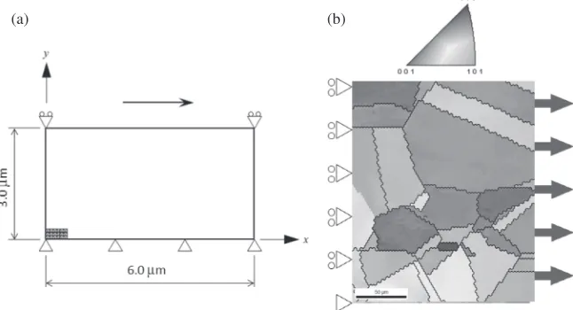
Figure 1(a) shows the FE model employed for the former set of simulations, which is divided into 60©32 crossed triangle elements (totally 7680 elements and 3933 nodes). Simple shear strain is applied to the upper edge of the sample
up to 20%, although the shear deformation has been done up to 60% under the experiment. Figure 1(b) displays, on the other hand, the analytical model for the latter, where the allocated initial orientation distribution is also shown. In both the series of simulations, roughly two conditions are assumed, i.e., with and without the FTMP-© model in the constitutive equation (hardening law, eq. (20)).
Discussions on the simulation results that follow will focus on the three points; (a) evolved substructures, (b) corre-sponding mechanical response, and (c) the relationship between (a) and (b) in terms of flow-evolutionary hypnosis based on duality diagram representations.
4. Results and Discussion
4.1 Single crystal in simple shear
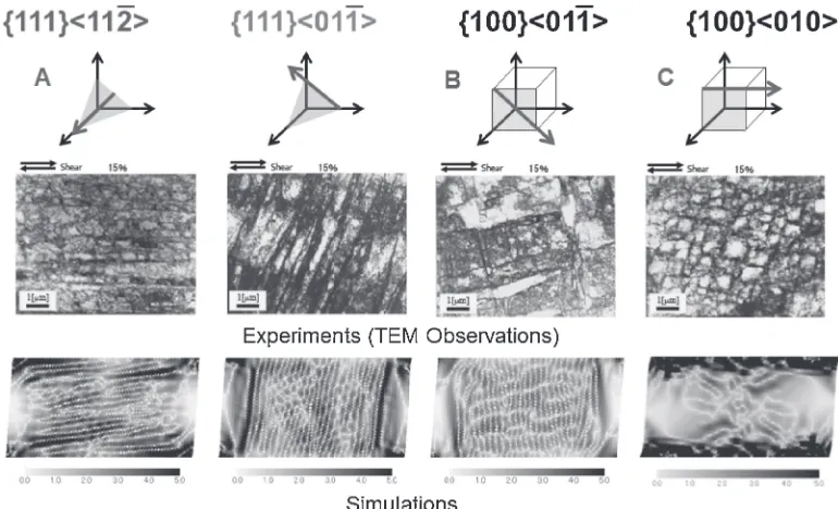
The work hardening behavior of single crystal steels with a BCC structure has been measured using the simple shear test in ferritic FeCr alloys.20) The deformation microstructures observed under the transmission electron microscope are classified into three kinds of morphologies, i.e., those consisting of (a) one set of parallel dislocation boundaries, (b) two sets of dislocation boundaries and (c) equiaxed cells. Figure 2 displays the typical TEM micrographs for samples sheared in four different orientations used in the experi-ments.20) As shown in the micrographs, there are four different types of dislocation substructures evolved in the samples corresponding to the shearing directions of {111}h112i, {111}h011i, {100}h011i and {100}h010i. The two £-orientations, i.e.,{111}h112i and {111}h110i, exhibit dislocation substructures having a unidirectional morphology classified in (a), extended in parallel and inclination to the shearing direction, respectively. The orientations{100}h110i and {100}h100i, on the other hand, yield (b) and (c) morphologies, respectively.
Let us focus on the two £-orientations, {111}h112i and {111}h110i. In the former case of shear direction, the primary slip system is so dominant that the lamellar-like dislocation structure parallel to {110} planes is formed, on the other hand, the different slip plane declined to 60° to the shear direction has been activated in the latter case.
(a) (b)
[image:5.595.137.460.74.249.2]Figure 2 also compares the corresponding FTMP-based simulation results with the micrographs, where dislocation density contours are presented. The experimentally-observed morphologies of the evolved dislocation substructures are successfully and naturally reproduced by the present simulation.
A significance of the present simulation can be easily understood if we examine the corresponding results to the above without using the FTMP-© model, in the sense that what will happen if we do not use the FTMP-© model. Simple shear simulations are performed without introducing the FTMP-© model, otherwise the analytical conditions are identical. Contour diagrams of dislocation density and incompatibility are shown in Figs. 3 and 4, comparing the two £-orientations as well as the analytical conditions with and without the FTMP-©model. Evidently, one finds almost no substructure emerges if the FTMP-©model is not used in the simulation (Fig. 4). This eloquently proves the critical
role of the incompatibility tensor in simulating the evolu-tionary aspects of dislocation substructures.
The incompatibility tensor, in the present context, represents a sort of“destination”of the released elastic strain energy that has been excessively stored. The “destination” must be appropriately prescribed in the simulations by the projection direction as specified by eq. (14), associated with the crystallographically-designated slip systems. Accord-ingly, the resultant patterns, e.g., those in the dislocation density contours, yield morphologies corresponding to thus-prescribed destinations.
For the present cases, both {111}h112i and {111}h011i, shown in Fig. 2, tend to yield roughly single slip activity, resulting in the unidirectional patterns, whereas {100}h011i exhibits activations of two sets of equivalent slip systems, resulting in the two-directional pattern. The multiple slip activity in{100}h010i, on the other hand, brings about nearly isotropic (equiaxed) morphology.
Fig. 2 Comparison with TEM observations for dislocation substructures under simple shear for single crystal stainless steel (BCC).
Fig. 3 Simulated substrucutres for two typical£-orienations under simple shear with FTMP-©model, where dislocation density and representative incompatibility contours are shown.
[image:6.595.104.489.69.303.2] [image:6.595.305.543.341.510.2] [image:6.595.48.288.344.500.2]Also to be noted that the simulated patterns are essentially unaltered even when the number of mesh divisions are changed, as far as the evaluation range for the derivatives (in carrying out the curl operations for obtaining the incompat-ibility tensor) is the same. In other words, the present model-based simulations can express the absolute size dependency of the evolved patterns, which is solely specified by the evaluation size of the derivatives. The effect of the evaluation range on the incompatibility patterns is systematically examined in Ref. 4).
4.2 Polycrystal in tension
Following the above, we also conduct a series of simulations on polycrystalline sample, where the
EBSD-Wilkinson method has been applied to directly measure the elastic strain distribution, in conjunction with a tensile test.21) Corresponding FEM analysis is performed to the experiment; the simulation used the identical initial conditions measured before the loading, i.e., the orientation distribution and residual strain (both with thefluctuations). Thefinite element model with the allocated initial orientation distribution employed is already shown in Fig. 1(b), where plane stress condition is assumed, since the EBSD-Wilkinson measure-ment has been done on the specimen surface in the experiment.
Figure 5 displays an example of comparison between the EBSD-Wilkinson method-based strain contour and the corresponding FTMP-based simulation result (via finite
Fig. 5 Comparison of elastic strain contour between experiment13) and
simulation with FTMP-©model. Fig. 6imentally-measured KAM value.Comparison of simulated dislocation density contour with exper-14)
[image:7.595.50.282.68.241.2] [image:7.595.312.547.70.247.2] [image:7.595.134.456.300.565.2]element method). Here, our focus is on “hard grains” and
“soft grains” marked in Fig. 5 as #1 & 2 and #3 & 4, respectively. Note, the “hard”grain, in the present context, means to yield elastically stiffer stress response than the prescribed one (based on Young’s modulus for the corre-sponding orientation), while the“soft”grain means to show more compliant response than the counterpart. For detailed discussions regarding this, refer to Ref. 19).
In addition to the distinction between hard (#1 & 2) and soft (#3 & 4) grains, subtle undulations emerging intra-granularly are well reproduced in the present simulation. Comparison of the simulated dislocation density contour with experimentally-evaluated KAM value distribution is shown in Fig. 6, where qualitative agreements between the two are confirmed.
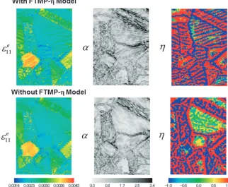
For comparison, the simulated strain contour without using the FTMP-©model is displayed in Fig. 7, where dislocation density and incompatibility tensor contours are also pre-sented. Evidently, the substructures emerged in the strain contour stems from the evolved incompatibility distribution. Although the elastic strain distribution as a whole can also be roughly reproduced even without the FTMP-© model, i.e., hard and soft grains are similarly distinguished, the detailed inhomogeneity observable in the experiment is failed to be captured.
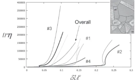
The significance of such detailed inhomogeneity in terms of controlling the local/overall stress responses is ought to be confirmed. To this end, we examine the duality diagram representation for the present simulation results. Duality diagrams obtained for the hard and soft grains are compared in Fig. 8. The hard grains (#1 & 2) exhibit larger amount of stored elastic strain energy¤Uefollowed by sharp rise intr©, implying abrupt energy release into local plastic flow. The soft grains (#3 & 4), on the other hand, yield relatively smaller ¤Ue followed by gradual increase in tr©, meaning more energy tends to be stored. What is implied from these results is that the evolved dislocated patterns are responsible for energy capacitor, storing excessive amount of strain energy in it, which can be used (consumed) in the future.
The duality diagram-based representation demonstrates the attendant difference between with and without the FTMP-© model. The results are qualitatively the same, but the case with the FTMP-© model tends to exhibit slightly larger amount of energy storage than the other for both set of the grains. This implies that the subtly evolved intra-granular substructures can have an ability to reserve excessive energy, which is to be consumed during the following course of deformation. The duality diagram representation enables us to look into the energyflow that is responsible for driving the evolutionary aspects of the inhomogeneity of interest in a tangible manner, as demonstrated above. It provides us with a sort of“balance sheet”among the energyflow, e.g., storage, flow-in/out and dissipation associated with the evolving inhomogeneous deformation.
Since the components of the elastic distortion tensor are measurable by the EBSD-Wilkinson method, or else those of the plastic distortion tensor by the digital correlation method, we can easily evaluate the incompatibility tensor as well as the elastic strain energy, to be used in drawing the corresponding duality diagram.
5. Conclusion
In this paper, we propose a simulation model and the associated scheme based on field theory of multiscale plasticity (FTMP) that enables effective predictions and evaluations of evolving dislocation/intra-granular substruc-tures to be observed in deforming crystalline materials. The incompatibility tensor in FTMP is shown to be powerful in the following two contexts. One is its excellent descriptive capability for capturing the underlying microscopic degrees of freedom, applicable to modeling of the corresponding substructural evolutions. The other is the ability as a parameter that can effectively measure the associated energy flow from elastically/locally stored states into local plasticity that is essentially dissipative. The latter can be embodied via duality diagram based on the flow-evolutionary working hypothesis. Combining the two approaches, we clarify both qualitatively and quantitatively how and why the substruc-tures are evolved and, furthermore, control the macroscopic stress response. We can conclude that measuring/modeling the evolving substructures, which are often overlooked or ignored in conventional approaches, are critical in under-standing elasto-plasticity of the materials of interest. Also, to be noted that the present simulation scheme can be easily extended into full-3D conditions, allowing us to investigate further the underlying mechanisms that can critically control the mechanical responses of the targeted materials, based on which we can highly expect synergy effects when combined with experimental measurements and/or observations.
Far more details about the underlying mechanisms by which the evolving substructures control the multiscale responses deserve further examinations.
REFERENCES
1) T. Hasebe:Interact. Multisc. Mech.2(2009) 114.
2) T. Hasebe:Interact. Multisc. Mech.2(2009) 1530.
3) Y. Aoyagi and T. Hasebe:Key Eng. Mater.340341(2007) 217222.
4) Y. Aoyagi, T. Hasebe, J.-S. Chen and P.-C. Guan:Interact. Multisc. Mech.1(2008) 423435.
5) T. Hasebe: IUTAM Symposium on Mesoscopic Dynamics of Fracture Process and Materials Strength, ed. by H. Kitagawa and Y. Shibutani, (Kluwer, Dordrecht, The Netherlands, 2004) pp. 381390.
6) T. Hasebe: Trans. MRS-J29(2004) 36193624.
[image:8.595.310.541.71.208.2]7) T. Hasebe: Comp. Mech. Eng. Sci. (CMES)11(2006) 145155. 8) T. Hasebe: Acta Metall. Sin.2(1998) 194197.
9) T. Hasebe and Y. Imaida: Progr. Mech. Behavior Mater. III(1999) 10771082.
10) D. Raabe: Comutational Materials Science: The Simulation of Materials, Microstructures and Properties, (Wiley, 2004).
11) T. Hasebe, S. Kumai and Y. Imaida:J. Mater. Process. Technol.85 (1998) 184187.
12) K. Kondo: RRAG Memoirs, (1955)1D-I, pp. 458469.
13) A. W. McDavid and C. D. McMullen: http://arxiv.org/abs/hep-ph/ 0609260, (2006).
14) E. Kröner:Kontinuumstheorie der Versetzungen und Eigenspanungen,
(Springer-Verlag, 1958).
15) R. J. Asaro:J. Appl. Mech.50(1983) 921934.
16) A. Khan and S. Huang:Continuum Theory of Plasticity, (Wiley, 1995). 17) S. Nemat-Nassar: Plasticity, A Treatise on Finite Deformation of
Heterogeneous Inelastic Materails, (Cambridge Univ. Press, 2004). 18) S. Suzuki, M. Isshiki and K. Mimura: Ferrum10(2005) 491496. 19) P. Franciosi:Acta Metall.31(1983) 13311342.
20) A. Uenishi, N. Sugiura, Y. Ikematsu, M. Sugiyama, E. Isogai and S. Hiwatashi: Proc. 2nd Int. Symp. on Steel Science (ISSS2009), Kyoto, (2009).