Effect of Forging Temperature on Microstructure and Mechanical Properties
of
In Situ
(TiB+TiC)/Ti Composites
Feng-cang Ma
1;2, Wei-jie Lu
1, Ji-ning Qin
1and Di Zhang
1;*1
State Key Laboratory of Metal Matrix Composites, Shanghai Jiao Tong University, Shanghai 200030, P. R. China
2Henan University of Science and Technology, Luoyang 471039, P. R. China
In this paper, 5 vol% (TiB+TiC)/Ti-1100(Ti–6Al–2.75Sn–4Zr–0.4Mo–0.45Si) composite were fabricated usingin situtechnologies between Ti and B4C powders. Phase identification was carried out by X-ray diffraction.transus temperature of the composite was measured by metallographic techniques. The composite after ingot breakdown was forged in various temperature ranges. Microstructure of the composite after forging at various temperatures was studied by optical microscopy (OM). Mechanical properties of the composite after forging at various temperatures were evaluated by tensile tests at 873 K. It was found that thetransus temperature of the composites was around 100 K higher than that of monolithic Ti-1100 alloy. Different microstructures were obtained after forging at different temperatures. The composite with different microstructures offered different mechanical properties, which was shown in the tensile tests. [doi:10.2320/matertrans.47.1750]
(Received December 26, 2005; Accepted April 24, 2006; Published July 15, 2006)
Keywords: in situ titanium matrix composites, forging temperature, microstructure, mechanical properties
1. Introduction
With the rapid development of technology in aerospace and atomic energy, the requirement for materials for such applications is increasing. Titanium matrix composites (TMCs), reinforced with ceramic particles, have considerable potential for improving properties and service temperature and can be extensively applied in areas such as aerospace, advanced weapon systems and the automotive industry, because of their high specific strength, good specific modulus and resistance to elevated temperatures.1,2)TMCs with better
properties can be prepared by the in situ technique. Compared to powder metallurgy method, the preparation process byin situtechniques is simple and equipments used in traditional casting also can be used in this method. Furthermore, this method overcomes the shortcomings of traditional techniques, such as the problems of pollution of reinforcements and wettability between ceramic particles and matrix encountered in the casting technique. Thereforein situ synthesized TMCs have been widely studied.3–5) However,
the machining property of these composites is inferior because of the distribution of the reinforcement with high hardness in the soft matrix. It is difficult to machine a work-piece with complex configuration, which restricts the application and development of the composites. In order to solve these problems, hot forging of materials can be used, which saves raw materials and reduces cost. On the other hand, Ti-1100(Ti–6Al–2.75Sn–4Zr–0.4Mo–0.45Si) is a near
Ti alloy. Because of their superior microstructure stability, toughness and excellent specific strength, near Ti alloys and its composites (TMCs) are used very popular for structural applications at high temperature. NearTi alloys offer considerable scope for obtaining a variety of micro-structures by thermomechanical processing6)(TMP). Alloy
specific studies have demonstrated significant benefits of using thermomechanical processing to alter microstructure and mechanical properties of nearTi alloys.7–10)
In this paper, 5 vol% (TiB+TiC)/Ti-1100 composites
were fabricated usingin situreactions between Ti and B4C
powders. transus temperature of the composite was measured by metallographic techniques. The composite after ingot breakdown was forged at various temperatures. Micro-structure of the composite after forging was studied by optical microscopy (OM). Mechanical properties of the specimens were evaluated by tensile tests at 873 K.
2. Experimental Procedure
For preparing 5 vol% (TiB+TiC)/Ti-1100 TMCs, the raw materials were grade I sponge titanium (99.95 mass%, average particle size: 1–5 mm), B4C powders (99.8 mass%,
average particle size: 5–7mm), aluminum thread (98 mass%), silicon (99.5 mass%, average particle size: 10–20mm), sponge zirconium (98.8 mass%, average particle size: 1–5 mm) and master alloys of other alloying elements such as Ti– Sn and Al–Mo. The nominal alloy composition of Ti-1100 was Ti–6Al–2.75Sn–4Zr–0.4Mo–0.45Si and the amount of B4C powders added in the present material was 1.86 mass%.
Firstly, the stoichiometric amounts of sponge titanium, B4C
powders, Al thread, sponge Zr, and master alloys of Ti–Sn and Al–Mo were blended thoroughly, and then they were compacted into pellets with a mold using a hydraulic pressure machine (the maximum pressure is 2107N). The size of the pellets is 60 mm in diameter and 450 mm in length. The pellets were joined with the electrode of a consumable vacuum electrode arc remelting (VAR) furnace. Then, the pellets were melted homogeneously in the furnace. In order to ensure the chemical homogeneity of the composites, the ingots were melted at least three times. The reinforcements were synthesized utilized the reaction between Ti and B4C as
following reaction:
TiþB4C!4TiBþTiC ð1Þ
Phase identification was carried out via X-ray diffraction using D-max IVA automatic X-ray diffractometer. Metallo-graphic techniques were used to measure the transus temperature of the composite. The specimens for transus temperature tests were cubes with a gauge size of 10 mm. The *Corresponding author, E-mail: [email protected]
specimens were heated in a box furnace with a temperature accuracy2K, after hold for 30 minutes then quenched into water. The forging of the composite was performed using a hydraulic pressure machine (the maximum pressure is
3106N). The molds were heated to 1073 K before forging,
and the temperature of specimens during forging was measured using infrared ray techniques. The amount of deformation was calculated as the total reduction in cross section (The total reduction in cross section isA0=Ai, where
A0is the cross sectional area before hot forging andAiis the cross sectional area after hot forging). The specimens after forging were quenched into water. Specimens for optical microscopy (OM) were cut from hot-forging rods. Then the specimens were prepared using conventional techniques of grinding and mechanical polishing. The specimens were etched in Kroll’s reagent (composition: 1–3 mL HF, 2–6 mL HNO3, 100 mL water). The microstructure of specimens was
characterized using a LECO2000 optical microscopy. The hardness values of the composite were measured by an HR-150A hardness test. The size of specimen plate for tensile tests was 1.5 mm in thickness and 40 mm in length. They were machined from hot-forging rods with the specimen axis parallel to the hot-forging direction. Three specimens for each hot-forging treatment were tested using a SHIMADZU AG-100KNA test machine. The average strain rate was
2:0103s1.
3. Results and Discussion
[image:2.595.320.533.272.431.2]3.1 Phase identification and reinforcement observation
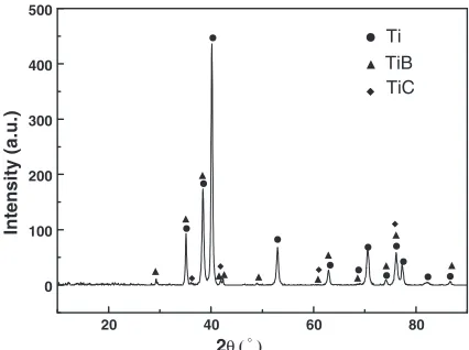
Figure 1 shows XRD patterns of the specimen after VAR. It confirms that Ti has reacted with B4C and TiB and TiC
have formed in composite during preparation process. The
optical microscopies of reinforcements of composites are presented in Fig. 2. The results of energy dispersion X-ray spectroscopic (EDS) study show that the gray needles are TiB, while the near-exquiaxed reinforcements are TiC. The different shapes of the reinforcements are related to their crystal structures and growth mechanisms during solidifica-tion process.11)
3.2 Thetransus temperature and various forgings of 5 vol% (TiB+TiC)/Ti-1100 composite
It is well known that transus temperature is a very important parameter for the thermomechanical processing of Ti alloys and its composite. Metallographic techniques were used to measure thetransus temperature of the composite, and the results were presented in Fig. 3. The transus temperature of the present composite was identified as
20 40 60 80
0 100 200 300 400 500
TiC TiB Ti
Intensity (a.u.)
2θ( )°
Fig. 1 X-ray diffraction patterns of 5 vol% (TiB+TiC)/Ti-1100 composite after VAR.
Fig. 2 Optical micrographs of reinforcement in the composite are presented in (a), and (b), respectively (unetched).
[image:2.595.130.470.480.608.2] [image:2.595.128.470.639.769.2]1398 K. The transus temperature of the composites was around 100 K higher than that of monolithic Ti-1100 alloy (thetransus temperature is around 1288 K).
From Ti-B and Ti-C binary alloy phase diagrams, it can be known that B is almost immiscible in-Ti matrix. The effect of B element ontransus temperature is not obvious. But the solubility carbon in-Ti matrix can reach about 0.3 mass%. So the reaction in eq. (1) during preparation of the composite could not perform completely, the increase of transus temperature due to B4C addition results from the dissolution
of carbon in matrix. Carbon is one of thephase stabilizers
for Ti alloys, and the effect of carbon in this experiment can be explained by Ti-Al-C ternary phase diagram. The matrix alloys containstabilizers Al, Sn, Zr, and O. The effect of these elements can be represented in terms of an Al equivalent content. According to Rosenberg,12) the
equiv-alent of Al content can be expressed as ½Aleq¼ ½Al þ ½Sn=3þ ½Zr=6þ10½O. The O concentration in specimens was ranged from 0.05% to 0.09%. For the present matrix alloy½Aleq falls in the range 8.1–8.6. Thus we can refer to
[image:3.595.76.263.220.469.2]the Ti-8Al-C phase system to discuss the transus temper-ature of the matrix alloy under study. A vertical section of the Ti-8Al-C phase diagram13)is shown in Fig. 4, and the present composition point of the composite is marked with A in Fig. 4. According to this vertical section, carbon increases thetransus temperature rapidly when the C concentration in matrix alloy is below 0.28 mass%. Thetransus temperature of the composite identified in this experiment is slightly lower than that presented in the Ti-8Al-C ternary phase diagram, which results from Mo and Si which are
stabilizers. From Fig. 4, it can be known that the ratio of the amount of carbon dissolved into matrix to that of carbon precipitated as TiC is about 7:3 for this composite attransus temperature.
According to the results oftransus temperature measured in this experiment and Fig. 4, three type forgings were conducted to the composite in this experiment, and the parameters used in this forgings are listed in Table 1, and
1100 1200 1300 1400 1500 1600
A3 A2
A
Composition of the composite
Temperature (/k)
Weight percentage
0.00 C 1.01 C
8.02 Al 91.98 Ti
8.0 Al 90.99 Ti β
β+Carbide
0.28%C
α
α +β+Carbide
α+β
A1
Fig. 4 Vertical Section of Ti-8Al-C equilibrium alloy phase diagram.
Table 1 Parameters used in various forgings.
No Forging temperature
range (K) Forging pressure
Amount of deformation
A1 1453–1403 4:1105N 4.3
A2 1373–1323 4:8105N 4.1
A3 1333–1263 6:5105N 4.6
[image:3.595.124.540.428.768.2]forging temperature ranges used in this experiment are also presented in Fig. 4.A1,A2andA3are usually named forging
in thephase field, forging in the (þ) field and forging started in the (þ) field and finished in thephase field, respectively.
3.3 Microstructure of the composite after forging at various temperatures
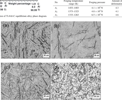
Optical microscopies of the composite before and after forging are presented in Fig. 5. From Fig. 5(a), it can be seen thatgrains of the composite in cast is coarser and the size of
grains is about 30–60 um. As presented in Fig. 5(b), Widmanstatten microstructure (containing (þ) lath grains totally) is obtained after A1 forging. As presented in
Fig. 5(c), bimodal microstructure (containing exquiaxed
grains and (þ) lath grains) is obtained afterA2 forging.
Generally, Ti alloys are usually thermomechanical processed in phase field or in (þ) phase field using isothermo-forging. Widmanstatten microstructure is obtained after thermomechanical processing in the phase field, and bimodal microstructure is obtained after thermomechanical processing in the (þ) phase field. But the microstructure (as presented in Fig. 5(d)) of the specimen afterA3forging is
quite different from common Widmanstatten microstructure or bimodal microstructure. The microstructure consists of near-exquiaxedgrains totally. The forming of the micro-structure results from the precipitation and growth ofphase
during forging. A3 forging was started at 1333 K (in the
(þ) phase field). When the temperature of the specimens felled below the þ! transus temperature during forging,phase transformed tophase. When theA3forging
started, primaryphase in the microstructure refined by the deformation, and the growth of new precipitatedgrains was restricted by primaryphase during forging. So finegrains were formed and residual phase distributed along the boundary ofgrains. The size ofgrains afterA3forging is
about 10–20 um.
3.4 Mechanical properties
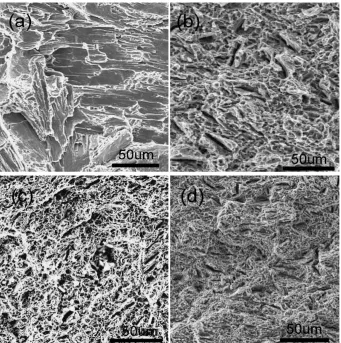
[image:4.595.306.549.327.392.2]The results of hardness and mechanical properties of the composite during tensile tests at 873 K are presented in Table 2. The typical SEM micrographs of the fracture surfaces of the composite are showed in Fig. 6. As Fig. 6(a) presented, a brittle cleavage fracture mode was observed in
Table 2 Mechanical properties of the composite after forged in various temperature ranges.
No Hardness (HRC) UTS (MPa) Elongation (%)
In Cast 39 592.4 <3
A1 47 750.3 8.3
A2 43 693.6 14.7
A3 46 722.4 15.6
[image:4.595.128.469.412.755.2]specimen in cast. But the fracture surface of the specimen after forging (Figs. 6(b), (c) and (d)) consists of the fine dimples. It shows a typical character of ductile fracture. As a result, the composites exhibit a significant improvement in ductility. From Table 2 and Fig. 6, it can be seen that effect of forging on improvement of mechanical properties of the composite is very obvious.
From Table 2, it can be seen that tensile strength of the specimens increase with the increasing in hardness. The specimen after A1 forging offers highest ultimate tensile
strength (UTS) and lower elongation, but the specimen after
A2 forging offers the higher elongation and lower strength.
This result is consistent with earlier reports,14) i.e. the Widmanstatten microstructure is more creep resistant than the bimodal microstructure. Thiehsenet al.15)have reported that ductility increased with the amount of equiaxed-phase in the microstructure.
It is notable that the specimen after A3 forging offers
higher UTS and highest elongation. The deformation performed until the material was in thephase field during such treatment, which resulted in work hardening caused by the generation and pilling up of dislocations during defor-mation. On the other hand, fine grains also contribute to higher elongation and strength.
4. Conclusions
From this work, some conclusions can be drawn. Com-pared to the monolithic Ti-1100 alloy thetransus temper-ature of in situ 5 vol% (TiB+TiC)/Ti-1100 composite increase around 100 K, which results from the solute carbon in matrix. Different microstructures are obtained after the composites are forged in the different temperature ranges,i.e. Widmanstatten microstructure is obtained after forging in the
phase field, and bimodal microstructure is obtained after forging in the (þ) phase field. Microstructure containing fine grains totally is obtained after forging started in the (þ) phase field and finished in thephase field. During tensile tests at 873 K, the specimen of the composite with Widmanstatten microstructure offers highest UTS and lower elongation, and the specimen with bimodal microstructure offers higher elongation. But the specimen with finegrains microstructure offers higher UTS and highest elongation.
Acknowledgments
We would like to acknowledge a financial support provided by A Foundation for the Author of National Excellent Doctoral Dissertation of P. R. China under Grant No. 200332, National Nature Science Foundation of China under Grant No. 10577013, the Research Fund of Science and Technology Commission of Shanghai Municipality under Grant No. 04DZ14002, 0452 nm045, 03ZR14063, and the ItoYama Foundation.
REFERENCES
1) S. Ranganath: J. Mater. Sci.32(1997) 1–16.
2) W. J. Lu, X. N. Zhang, D. Zhang, R. J. Wu, Y. J. Bian and P. W. Fang: J. Mater. Eng. (in Chinese)8(1999) 9–14.
3) W. J. Lu, X. N. Zhang, D. Zhang, R. J. Wu, T. Sakata and H. Mori: Scripta Mater44(2001) 1069–1074.
4) H. T. Tsang, C. G. Chao and C. Y. Ma: Scripta Mater35(1996) 1007– 1015.
5) H. C. Man, S. Zhang, F. T. Cheng and T. M. Yue: Scripta Mater44 (2001) 2801–2806.
6) R. Boyer, E. W. Collings and G. E. Welsch (Eds.),Materials Properties Handbook: Titanium Alloys, (ASM International, Materials Park, OH, 1994) pp. 488.
7) G. Luetjering, J. Albrecht and A. Gysler: Titanium’92 Science and Technology, (Froes FH and Caplan I, Editors. Warrendale: TMS, 1993) pp. 163–165.
8) C. Andres, A. Gysler and G. Luetjering: Titanium’92 Science and Technology, (Froes FH and Caplan I, Editors. Warrendale: TMS, 1993) pp. 31.
9) W. Cho, J. W. Jones, J. E. Allison and W. T. Donlon: Proc. of Sixth World Conference on Titanium, (Lacomb P, Tricot R and Beranger G, Editors. Les Editions de Physique. 1989) pp. 187.
10) J. R. Wood, P. A. Russo, M. F. Welter and E. M. Crist: Mater. Sci. Eng. A243(1998) 109–118.
11) W. J. Lu, D. Zhang, X. N. Zhang, R. J. Wu, T. Sakata and H. Mori: Mater. Sci. Eng. A331(2001) 142–150.
12) H. W. Rosenberg:The science, technology and application of titanium
(ed. R. I. Jaffee and N. E. Promisel, New York, Pergamon, 1968) pp. 851.
13) P. Villars, A. Prince and H. Okamoto:Handbook of ternary phase diagrams, (Materials Park, OH, ASM International, Vol. 3, 1995) pp. 2907.
14) P. J. Bania and J. A. Hall:Titanium Science and Technology, (Deutsche Gesellschaft fur Metallkunde. Germany: Oberursel, 1985) pp. 2371. 15) K. E. Thiehsen, M. E. Kassner, J. Pollard, D. R. Hiatt and B. M.