FastLink II
Client Pack
Notice
The information in this manual is subject to change without notice, and should not be construed as a commitment by Bay Networks, Inc. Bay Networks assumes no responsibility for any errors that may appear in this document.
Remote Annex 2000, Remote Annex 4000, Remote Annex 6100, Remote Annex 6300, MSX 5390, MSX 5391, and MSX 5393 are trademarks of Bay Networks, Inc.
FastLink II © 1994-1996 Bay Networks, Inc. and Funk Software, Inc.
All rights reserved.
Proxy © 1992-1996 Funk Software, Inc. All rights reserved.
FastLink is a trademark of Funk Software, Inc.
MEWEL © 1993 Magma Systems.
Table of Contents
I-1 Introducing the FastLink II Client Pack
Overview ... 5
System Requirements/Compatibility... 7
About The Documentation ... 8
Technical Support ... 9
FastLink II Client Pack Diskettes and Licensing ... 10
I-2 Installing the FastLink II Client Pack
Overview ... 11Windows Installation... 12
DOS Installation ... 21
II-1 FastLink II Concepts
Clients and Servers... 23The Remote Access Administrator ... 24
Serial Ports ... 25
The FastLink II ODI Driver ... 26
II-2 The FastLink II User Interface
Overview ... 27The Connections Dialog... 29
The Setup Dialog... 40
The Modems Dialog... 44
The Scripts Dialog... 47
Displaying Port Statistics ... 51
Housekeeping ... 54
FLINK.EXE Command Line Options... 56
II-3 Connecting from DOS
Overview ...61
Before you Connect ...61
Making a Connection Manually ...62
Making and Breaking Connections with Batch Files ...66
Using FLCACHE Launch Protection and File Caching...66
II-4 Connecting from Windows
Overview ...69Before You Connect ...70
Before Running Windows ...70
Connecting to the Remote Access Server ...71
Connecting to NetWare File Servers ...71
Using Custom Windows Icons ...72
II-A FastLink II Connection Errors
Connection Error Messages...77III-1 Supported IP Stacks
Introduction...81Beame & Whiteside (BW-TCP 3.2) ...82
Frontier (SuperTCP for Windows) ...86
FTP (OnNet v2.1 for Windows) ...90
Microsoft TCP/IP-32 3.11 (WFW 3.11)...93
NetManage (Chameleon 4.01)...96
I-1 Introducing the FastLink II
Client Pack
Overview
Welcome to the world of remote network access. With the FastLink II Client Pack, you’ll be able to reach your network from anywhere via modem, and connect to all its resources just as if you were on premises — so you can do your work without being at work.
The FastLink II Client Pack includes two major components: the FastLink II Client and Proxy Remote Control.
The FastLink II Client
The FastLink II Client lets you dial in over a standard telephone line to a Bay Networks’ remote access server running Point-to-Point Protocol (PPP) protocol. Once connected, you become a full-fledged node on the network with IPX and IP access to all of its resources; you can log in to file servers, print to network printers, send and receive e-mail, and use any other network service that would normally be available to you when directly connected.
FastLink II has powerful features that make remote access easier and more productive than you might expect:
Dual DOS and Windows interfaces make it easy to make and break connections any time.
Iconized connections from Windows let you create icons that dial, log in to servers, and run remotecontrol sessions automatically.
Proxy Remote Control
One of the most important things that your FastLink II connection allows you to do is run the powerful Proxy Remote Control software included in this package.
By installing the Proxy Master on your remote PC and the Proxy Host on your PC at work, you can take over and operate your PC at work from your home or from the road.
Proxy runs in Windows, and can take over any PC whether it is running DOS or Windows. Proxy can even take over more than one machine at a time; each remotely-controlled PC is displayed in a separate window.
Proxy has been optimized extensively to be super-fast over a dial-up connection!
Remote Node and Remote Control
Remote Node and Remote Control are two distinct methods of remotely accessing a network. They each have their advantages for different types of network operations:
Remote Node means you become a node on the network, log in to file servers, and perform other operations just as if you were directly connected.Use remote node when you’d like fast keyboard response, and when the amount of data passing over the phone line is modest. For example, reading e-mail or editing documents on the network are tasks well suited to remote node.
Remote Control means you use a program like Proxy to control a PC that is directly connected to the network. By using a PC on the network to do your work, you reduce the amount of data that must be transmitted over the phone line.Use remote control when your task would involve moving large amounts of data over the network. For example, performing a database search or running a program that’s not on your PC are tasks that are well suited to remote control.
A 386 or higher PC.
A high-speed serial port using a 16550A UART. For best results, we recommend that you purchase a 16550A-based serial COM port add-in card that contains a co-processor such as a Hayes ESP card.For a discussion of the different types of serial ports, see the “FastLink II Concepts” chapter. To determine which type you have, use the Comm Port Test feature described in the “FastLink II User Interface” chapter.
A modem, preferably capable of 14,400 bits/second or higher over a phone line. For best results, we recommend the use of a 28,800 bits/second (v.34) modem.
MS-DOS version 3.3 or higher.If you’d like to run FastLink II with Windows, you’ll also need:
Windows 3.1 or higher or Windows for Workgroups 3.11 or higher.FastLink II supports both standard and enhanced mode, though enhanced mode is recommended.
Proxy System Requirements
The Proxy Master software runs as a Windows or Windows 95 application, and requires a 386 or higher PC with at least 4 MB of RAM.
The Proxy Host software runs as a Windows or Windows 95 application, and requires a 386 or higher PC with at least 4 MB of RAM.
The DOS Proxy Host software runs as a memory resident program, and requires DOS version 5.0 or higher; it uses approximately 9K of conventional memory when loaded with the DPMS memory manager.
Proxy has been optimized extensively to be super-fast over a dial-up connection!
You can use Proxy over your FastLink II dial-up connection using either one of the following standard protocols:
IPX — usually run on networks using Novell NetWare. It is not necessary for either the master or host workstation to be logged in to a server, nor is it necessary to run a network client.For Windows 3.x you need the Novell 16-bit (VLM) or 32-bit Client IPX protocol support.
IP — a general purpose protocol supported on a wide variety of networks and servers.About The Documentation
This manual is in three parts:
Part I includes this introductory material plus instructions on installing the FastLink II Client Pack.
Part II describes how to use the FastLink II Client to establish a connection to a network over a phone line.
Part III documents the IP Stacks.Be sure to check each of your diskettes for a text file called README.TXT. This file contains late-breaking information not available in this manual.
Technical Support
If you have any problems installing or using the FastLink II Client or Proxy, there are various resources available to help you:
This manual and the README.TXT files on your diskettes may contain the information you need to solve the problem you are having
Your network administrator can probably answer many of your questions and give you valuable assistance in installing and using the product.
Technical Support Internet address is [email protected] (Burlington, MA) and[email protected] (UK). Most on-line services, such as CompuServe, America On Line, Delphi, and Prodigy offer an Internet e-mail gateway.
Contact our electronic bulletin board that can be reached at (617)273-1499, modem settings: 14,400, 8, 1, N, or FTP to bbs.xylogics.com.
Visit our world wide web server via the Internet, which can be reached at http://www.baynetworks.com.
Technical support representatives may be reached by calling 1-800-2LANWAN (800-252-6926). When prompted you should enter an ERC of 170.FastLink II Client Pack Diskettes and Licensing
You are entitled to use the programs on the diskettes according to the enclosed license agreements. Here, briefly, is a description of the contents of the diskettes and how the licensing of the various components works.
Remote PC diskettes
You are provided with a master copy of the following two diskettes used to install FastLink II on the remote PC. You may freely distribute and copy either of these diskettes for use in connecting to Bay Networks’ remote access server:
The FastLink II Client & Proxy diskette contains the install program (SETUP.EXE) and the software necessary to run the FastLink II Client. This diskette also contains the Proxy Master, which may be used with the FastLink II Client on the remote (dial-in) PC.
The Novell NetWare Files diskette contains the latest Novell client, including the NetWare VLM redirector and NetWare utilities including LOGIN.EXE (for NetWare 3.x or 4.x), LOGOUT.EXE, MAP.EXE, ATTACH.EXE, and SLIST.EXE.Network PC installation diskettes
The Proxy Host diskette contains the install program (SETUP.EXE) and the software necessary to run the Proxy Host. The Proxy Host is the machine you would like to view and operate from the remote PC.
You are provided with one or more licensed copies of a diskette used to install the Proxy remote control Host on a network PC. Each diskette contains a Proxy Host license which may only be installed on a single PC on the network.
I-2 Installing the FastLink II
Client Pack
Overview
These instructions describe how to install the FastLink II Client Pack on your PC. You can install either from DOS or from Windows:
The Windows installation process installs all the software you need to run FastLink II with either DOS or Windows.
The DOS installation process only installs FastLink II for use with DOS.The Windows installation creates a group with two types of icons:
An icon that invokes the FastLink II Client software
Custom icons that dial a remote access server, map drives, and establish Proxy sessionsWindows Installation
This section describes how to install the FastLink II Client Pack on your PC using Windows. Once installed, the FastLink II software can be used from either DOS or Windows.
Installing on the remote PC
To install the FastLink II Client and the Proxy remote control Master:
1 Run SETUP.EXE from the FastLink II Client diskette.
To do so, insert the FastLink II Client diskette in drive A or B, issue the File Run command from Program Manager, then enter:
A:\SETUP ↵↵ (from A:) or B:\SETUP ↵↵ (from B:)
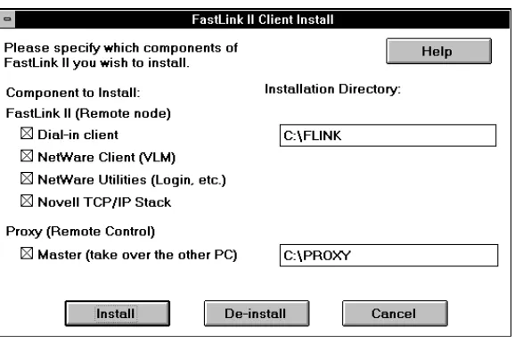
[image:12.612.183.472.248.441.2]The following dialog appears:
The following table describes the available options:
Option
Description
FastLink II (Remote Node)
Dial-in client
Installs the FastLink client
NetWare Client
Installs the Novell NetWare client with VLM support
NetWare Utilities
Installs NetWare Utilities, including LOGIN.EXE
Novell TCP/IP stack
Installs the Novell LAN Workplace TCP/IP stack,
PING.EXE, and TRACERT.EXE (trace route)
Installation Directory
Directory for FastLink II client and NetWare files
Proxy (Remote Control)
Master
Installs the Proxy Master
Installation Directory
Directory for Proxy Master files
The default is to install the FastLink II Dial-in Client, the Novell NetWare Files, Novell TCP/IP Stack and the Proxy Master — these are the modules you’ll want to have on the PC that you’ll be using remotely.
NOTE: To install the Proxy Host, run the SETUP program from the Proxy Host
diskette on the machine you want to take over.
Press [Install] to proceed with installation.
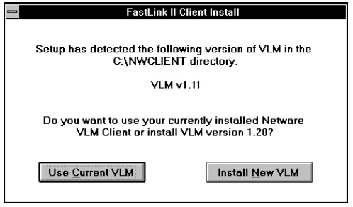
2 If you selected NetWare Client, and already have installed VLM support on your PC, you will be prompted to either use the VLMs you have installed, or install newer ones.
[image:13.612.234.483.390.536.2]A dialog similar to the following will appear if VLMs are detected:
Figure 2: VLM Already Installed Dialog
3 If you selected Novell TCP/IP Stack, this will install Novell’s LAN Workplace TCP/IP stack which lets you run IP-based applications.
Note: IP applications such as a Web Browser, FTP client, email client, etc., are not included with this package.
To use TCP/IP effectively you need to refer to a DNS (Domain Name System) server. DNS lets you use symbolic names (such as xyz.company.com) instead of specific IP addresses.
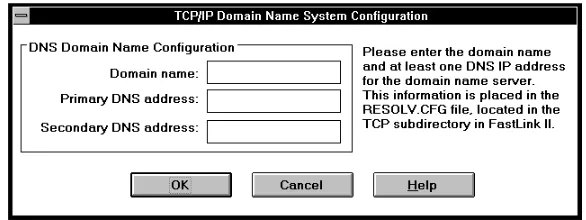
[image:14.612.178.471.158.268.2]A dialog similar to the following will now appear:
Figure 3: TCP/IP Domain Name System Configuration Dialog
You should now enter the following information:
Domain Name — the DNS domain name; each network uses a top-level domain name such as
company.com.
Primary DNS address — the IP address of the DNS name server that will be tried first to resolve symbolic names; if this server is not available, then the secondary DNS address will be tried instead.
Secondary DNS address — the IP address of the DNS name server that will be tried if the primary DNS address cannot be reached; if this server is not available, then the attempt to resolve the symbolic name will fail. This parameter is optional, but it is strongly recommended.
4 You may be prompted to overwrite files such as NET.CFG and FLINK.INI that may have been previously installed. For each of these prompts, answer [Yes] to overwrite the existing file, or [No]
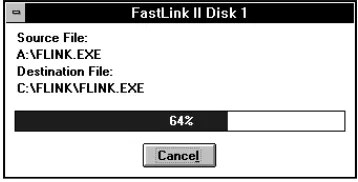
A file copy progress indicator will now appear:
Figure 4: Copy Progress Dialog
To cancel the copy operation hit the [Cancel] key; this will prompt you to abort the installation operation.
5 After the file copy, you will be asked to select one of the two supported connection types for your Remote Annex Software.
The following dialog will now appear:
Figure 5: PPP or SLIP Selection Dialog
Click on the connection type you wish to use:
PPP — Choose this if you are running Remote Annex Software Release 10.1 or higher. This selection enables IPX and IP remote access over PPP.
[image:15.612.272.442.270.420.2]6 You will now be asked if you wish to configure the FastLink II client settings. The following prompt will now appear:
Figure 5: Initialization Confirmation Prompt
If you answer [Yes] to configure the settings now, the FastLink II client will be started with the Setup dialog chosen for you.
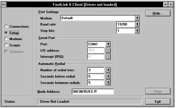
The following dialog will now appear:
Figure 6: FastLink II Setup Dialog
[image:16.612.183.470.234.410.2]Concepts” and “The FastLink II User Interface” for more information on configuring FastLink II.
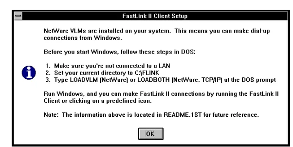
[image:17.612.203.504.112.263.2]7 If you installed the NetWare Client you will get a message stating that VLMs are installed on your system. This screen includes information on the batch files to load your dial-up stack for NetWare and/or TCP/IP.
Figure 7: NetWare Information Dialog
Click [OK] to continue.
8 A final screen appears with a message stating that the software has been successfully installed. In addition, you will be asked to reboot your PC so that any changes to your system files can take place.
Figure 8: Final Install Dialog
[image:17.612.261.452.349.491.2]Installing Proxy Host on the network PC
The Proxy Host can be installed from Windows or Windows 95. There are some differences between the Windows and Windows 95 installation; however, the installation steps are identical. Before installing the Proxy Host, make sure that you close all other applications that you have running.
To install the Proxy Host from Windows or Windows 95:
1 Use the Windows 95 Start Run or Windows Program Manager File Run command, and run SETUP.EXE. For example, to install from the diskette in drive A or B you would enter:
A:\SETUP ↵↵ (from A:) or B:\SETUP ↵↵ (from B:)
2 You will be presented with the introductory “Welcome” dialog. Click Next to continue.
3 You will be presented with the “Software License Agreement” dialog. Before proceeding, make sure that you read and agree with the terms of the license agreement. Click Yes to accept the license agreement terms and continue
4 You will be presented with the “Choose Destination Location” dialog. You may either use the default destination directory, enter a new one, or click Browse to search for a directory. Click Next
to use this installation location and continue.
5 You will be presented with the “Select Program Folder” dialog. You may use the default folder name Proxy, enter a new one, or choose from an existing folder. Click Next to use this installation location and continue.
6 You will be presented with the “Proxy Host Setup" dialog. Set the Proxy Host station Name and Password that will be used to identify your PC to Proxy Masters as follows:
Name is a unique host station name that identifies the PC to a Proxy Master that may want to connect to this host. You should make sure that the name you assign is different from that of other host PCs, or Proxy will not be able to tell them apart.
You will probably want to assign a station name that makes it easy to identify the PC. Combining the name of the person who uses the PC with the PC’s brand or type is usually a good practice; for example, “Jean’s P200” or “Gracie’s Model 60.”
7 You will be presented with the “Start Copying Files" dialog prior to actual file copying. At this point, you can go back to any previous dialog and change your answers by pressing Back. Click Next to start copying the Proxy files and continue.
8 Setup is now finished copying files to your PC. Click Finish with Restart Windows now checked to restart Windows and complete the installation process.
9 You will receive a final message box requesting that Windows be restarted. Click Restart Windows. Your PC will now be available as a Proxy Host whenever you start Windows.
System File Modifications During Installation
During installation from Windows, certain modifications will be made to your system files:
When the FastLink II Client is installed, a line is added to your AUTOEXEC.BAT that loads a Novell program called DPMS.EXE, if it is not there already.DPMS is an extended memory driver that allows the FastLink II driver to reduce its DOS footprint dramatically.
When the Novell NetWare files are installed, the following changes are made to accommodate VLM installations:−− In CONFIG.SYS, lastdrive=z is inserted, or existing lastdrive settings are modified to
lastdrive=z.
−− In WIN.INI, nwpopup.exe is inserted in the [Windows] section
−− In SYSTEM.INI, various items are inserted for the VLM client
When the Proxy Master is installed, no changes will be made to your system files.
When the Proxy Host is installed, your SYSTEM.INI file is modified as follows:−− In the [boot] section — user.exe=user.exe changes to user.exe=phostusr.exe. This allows Proxy to control your display, keyboard, and mouse when Windows starts, and launches PHOSTWIN.
−− In the [386enh] section — device=prxv.vxd is added for Windows 3.x.
−− A [Proxy Host] section is added to record settings for Proxy.
In Windows 95, Proxy Host is added to the Add/Remove Programs area in your Control Panel; if selected, this will remove the Proxy Host from your PC.
NOTE: Modified system files such as WIN.INI, SYSTEM.INI, AUTOEXEC.BAT, and
DOS Installation
This section describes how to install the FastLink II Client on your PC in DOS.
To install the FastLink II Client, start from the DOS prompt and:
1 Insert the FastLink II Client diskette in drive A or B, then make that drive current by typing either A:
or B:, then pressing ↵↵.
2 Enter the following command:
FINSTALL ↵↵
Follow the directions on the screen. The FINSTALL program copies the FastLink II Client software into the directory of your choice.
3 Select the PPP or SLIP version of the FastLink II Client.
PPP - Choose this if you are running Remote Annex Software
Release 10.1 or higher. This selection enables IPX and IP remote access over PPP.
SLIP - Choose this if you are running a Remote Annex Software Release that is earlier than Release 10.1. This selection enables IPX remote access over SLIP.
3 Make the FLINK directory current and type:
FLINK ↵↵
The FastLink II main menu will appear.
4 Select Setup. The Setup dialog will appear.
You can now enter configuration information required by FastLink II to operate your system:
Serial Port — Set the Serial Port to the port to which your modem is connected. Normally, this will be either COM1 or COM2.
Modem — Select a Modem from the list of preconfigured modems. Select Default if your modem does not appear on the list.
NOTE: DPMS is a Novell extended memory driver that allows the FastLink II ODI driver to reduce its DOS footprint dramatically.
II-1 FastLink II Concepts
Clients and Servers
In the world of remote access, you’re either a client or a server.
A remote access client is a PC that can connect to a remote access server over a telephone or other remote link, and thereby get a connection to the network. Your PC becomes a remote access client when you use the FastLink II Client software to connect to a remote access server.
A remote access server is a piece of hardware and/or software that is connected to a network and can accept calls from clients who want access to that network. The job of the remote access server is to connect clients to the network.A Bay Networks’ Remote Annex server is an example of such a server. The Remote Annex server accepts calls from the FastLink II Client.
The Remote Access Administrator
The Remote Annex Administrator is the person in charge of maintaining your remote access server and making sure that people are able to connect to it.
Your administrator should provide you with:
A user name that identifies you to the Remote Annex server.
A password to allow the Remote Annex server to authenticate your identity.
The phone number of the Remote Annex server.Serial Ports
Your PC and modem communicate with each other over a serial port. The type of serial port you have and the speed (baud rate) you set it to affect the performance of your FastLink II connection.
The most common type of serial port is based on the 8250 and, more recently, the 16450 Universal Asynchronous Receiver Transmitter (UART). This type of serial port handles a single character at a time in either direction.
An enhanced serial port, called the 16550 UART, is now used in many high-end workstations and laptops. The 16550 can buffer up to 16 characters at a time in either direction. Because it can buffer so many characters, the risk of losing data is minimized and the serial port can operate at a higher baud rate and at a lower error rate.
NOTE: You can find out which type of serial port(s) you have by using
FastLink II’s Comm Port Test option. For more information, refer to the section “Housekeeping.”
All this leads up to the $64 question: What baud rate should you set the serial port to?
First, you need to know what baud rate your modem requires. It’s possible that your modem requires a specific baud rate and you’ll have to set your serial port to that.
But most modern modems automatically adjust to any baud rate you set. So here are some rules of thumb:
Set the highest baud rate possible to get the most benefit out of the compression in your modem. Experiment with different baud rates, checking Port Statistics to make sure that the error rate isn’t too high. (The ratio between Rx Total and Rx Errors should be about 10,000 to 1 or better.)The FastLink II ODI Driver
ODI (Open Data-link Interface) is the Novell standard upon which network communications is based. The ODI standard describes the different layers required for network communications and how they should interact. FastLink II is fully compliant with this standard, and allows you to operate standard Novell networking software transparently.
You may already be familiar with other ODI drivers. NE2000.COM, for example, is an ODI driver that operates an Ethernet card, just as the FastLink II ODI driver operates a modem or other communications device.
The FastLink II ODI driver (FLODI.COM) is the main component of FastLink II. It allows communication with a Remote Annex server that uses Point-to-Point protocol (PPP), a standard data-link level protocol.
The FastLink II ODI driver allows both IPX and IP protocols to run over the PPP connection. FastLink II includes Novell’s IPX and LAN Workplace IP stack. There are also numerous vendors that supply IP stacks which are also compatible with FastLink II.
These are the various components that must be loaded to establish an IPX connection and attach to NetWare servers. These are, in order of loading:
LSL.COM — The Link Support Layer. This is the “traffic cop” that manages the communication between ODI drivers and protocols such as IPX and IP.
FLODI.COM — The FastLink II ODI driver. This module sends and receives packets of data over the phone line on behalf of IPXODI or an IP ODI driver.
IPXODI.COM — The IPX protocol. IPXODI finds the FastLink II ODI driver and uses it for all packet communications over the network.
VLM.EXE or NETX.EXE — One of these must be loaded before you can attach to NetWare file servers. Both use IPX to communicate with file servers. NETX is the older NetWare shell technology. VLM is the newer NetWare redirector and provides improved performance (burst mode) and additional features that are useful for remote access.
You can establish an IP connection at the same time that you run IPX. Depending on the IP stack you are using, you may need to load additional TSRs, or make changes to your system files.
NOTE: Refer to your IP stack vendor’s documentation for how to load TSRs and modify your system files. See the FastLink II IPSTACKS.HLP help file for the latest information on IP stack
II-2 The FastLink II User
Interface
Overview
The FastLink II User Interface can be run from DOS or Windows:
FLINK.EXE is the DOS version of the user interface.
FLINKW.EXE is the Windows version of the user interface.FLINK.EXE and FLINKW.EXE perform mostly the same functions and operate the same way. You can use one or the other as the need arises.
The sections that follow describe the dialogs that allow you to control FastLink II. In most cases, the documentation refers to Windows dialogs as examples, but since these dialogs contain the same options as the DOS dialogs, you can use them as reference whether you are running FastLink II from DOS or Windows.
At the end of this chapter, you’ll find information on running FLINK.EXE and FLINKW.EXE with command line parameters. Command line operation of FastLink II lets you use batch files in DOS or icons in Windows to automate connecting and disconnecting.
While this chapter describes how to connect to a Remote Annex server from the Connections dialog, before you actually attempt a connection you should read one of the chapters that follow: either “Connecting From DOS” or “Connecting From Windows”. Those chapters will give you more complete information on how to set up your system in general prior to connecting.
The FastLink II User Interface runs whether or not the FastLink II ODI driver has been loaded; if it is not loaded you won’t be able to connect to a server, though you will be able to change settings.
Operation
Instruction
To select a menu item
Use the up and down arrows to select the
item you want, then press [Return].
To move the highlight from one item to
another
Use [Tab] and [BackTab].
To use a drop-down box
Highlight the box and press [Return], use
the up and down arrows to select the item
you want, then press [Return].
To use a checkbox
Highlight the item and press [Space] to
check or uncheck the box.
To select a radio-button
Highlight the selected item, then use the
up and down arrows to change the
selection.
To modify an edit field
Highlight the field and use left and right
arrow, [Del], [Backspace], and standard
text keys to edit the data.
To press a command button
Press the function key ([F1], [F2], etc.)
shown on the button.
To return to the previous screen
Press [Esc].
To return to DOS from any dialog
Press [Alt-F10].
Running the FastLink II User Interface from Windows
To run the FastLink II User Interface from Windows, use the File Run command and type the following:
C:\FLINK\FLINKW
You can also double-click the FastLink II Client icon in your FastLink II Windows group. Either way, the FastLink II User Interface appears with the Connections dialog displayed.
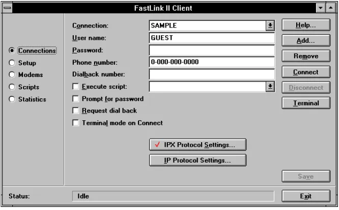
The Connections Dialog
The Connections dialog is the focal point of activity in FastLink II. It is from this dialog that you connect and disconnect from servers, and save the characteristics of connections for future use. Specifically, you can:
Connect to a server
Disconnect from a server
Create and remove named connections
Edit the settings for any connection
Enter terminal mode to view modem activity, operate the modem directly if necessary, or communicate with security devices at the serverA connection is a named collection of settings that describe how to dial up a server.
If you always connect to the same server, you may need only one connection. If you call different servers, or need to use different settings for different purposes, you can create a named connection for each.
Connection settings include:
Your user name and password, to allow the server to authenticate your identity
The phone number of the server
An option to request that the server dial you back at a specified phone number
An option to use a predefined dialing script when connecting
An option to pop up Terminal mode when connecting
Settings for the IPX protocolTo display the Connections dialog, check the Connections button at the left of the screen. A dialog similar to the following appears:
Figure 2: Connections Dialog
Editing Connection Settings
To edit the settings for a connection:
1 Highlight the Connection drop-down box, and select the connection whose settings you want to edit.
2 Edit any of the individual settings, as described in the sections below.
3 Press [Save] to make your changes permanent.
User name
Your Administrator will assign you a user name. Your user name identifies you to the Remote Access server. To enter your user name, highlight the User name field and enter the name your Administrator assigned you.
Password
Your Administrator will assign you a password. This password allows the Remote Annex server to authenticate your identity.
1 Highlight the Password field and enter your assigned password.
The password appears as asterisks as you type, so be careful to enter it correctly.
2 If the Prompt for password box is checked, uncheck it.
You can also specify that your password is required each time you connect.
1 If the Password field is not blank, highlight it and press [Del] to remove any password you may have previously entered.
2 Check the Prompt for password box.
Phone number
This is the phone number of the server. Your Administrator can supply you with this number. Your modem uses this number to gain access to the network.
To specify the phone number, highlight the Phone number field and enter the phone number of your server. If any special access codes or modem controls (such as pauses) are required, be sure to include them.
Dialback
Dialback is a two-step process. First, your PC dials the server, and, after exchanging some information such as your phone number, both sides hang up. Then the server dials your PC and establishes a connection.
If you want to use dialback:
1 Check the Request dialback box.
2 Highlight the Dialback number field and enter the phone number of your modem.
If you don’t want dialback, uncheck the Request dialback box.
NOTE: Your Administrator may have set up special rules for dialback. For security purposes, you may be required to use dialback, and only from particular phone numbers known to the
server. It’s also possible that you are precluded from using dialback. Your Administrator can help you set up the proper dialback options.
Execute Script
You can execute a script which allow you to easily automate connections to a Remote Annex server with front-end security.
To specify a script to use, highlight the Execute Script drop-down box and select a script from the list.
NOTE: If you plan to connect to a terminal server that prompts with "Login:" and "Password:",
choose Standard, or use the Scripts dialog to create a new script for your Remote Annex server.
Terminal Mode on Connect
Terminal mode on connect is useful if you need to communicate with a communications server or security device that requires you to enter information before connecting to the Remote Annex server. Checking this box will automatically start Terminal Mode in the following situations:
When you click Connect, FastLink II will pop up the Terminal Mode screen, which is equivalent to pressing [Terminal].
If you run FastLink II from the command line with a connection name, the Terminal Mode screen will automatically pop up.IPX Protocol Settings
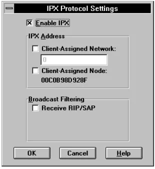
The IPX Protocol Settings dialog lets you configure the use of IPX over the connection. When you click the
[image:32.612.280.435.98.267.2][IPX Protocol Settings] button, a dialog similar to the following appears:
Figure 3: IPX Protocol Settings Dialog
If you’d like to use IPX, check the Enable IPX box.
NOTE: Novell NetWare uses IPX for all its communications. Be sure to check Enable IPX if you plan to log into NetWare file servers or use other programs that rely on IPX, such as Proxy.
Network and Node Address
When you connect, you will be assigned an IPX address that combines the Remote Annex server’s network number with a node address. FastLink II gives you a choice as to how your network and/or node address gets assigned:
Duplicate IPX Addresses
Your Remote Annex server does not let two users with the same IPX address connect simultaneously. If someone else with your IPX address has already dialed in, you will get an error when you try to connect.
If you use FastLink II’s node address that was generated at installation, the odds of this happening are very small. If it does happen to you, go to the Setup Dialog and generate a new random node address to resolve the conflict.
Your node address is saved in FastLink II’s configuration file, FLINK.INI. The most likely way for two people to get the same node address is by copying FLINK.INI. This might be done as a shortcut to configuring several similar machines. If you think your FLINK.INI may be a copy of someone else’s, just regenerate a new node address to be sure of avoiding conflicts.
Broadcast Filtering
The Broadcast Filtering settings let you suppress various types of broadcast packets from the network to reduce unnecessary traffic.
A broadcast packet is one which is not directed to one particular node, but to every node on a network. Networks are normally buzzing with broadcast traffic. File servers and other network services advertise their presence using broadcasts, routers keep each other up-to-date using broadcasts, client workstations search for servers to connect to using broadcasts, and so on.
The problem with broadcasts is that they get sent to everyone, even nodes that will ignore them. A large network with many servers and routers can generate levels of broadcast traffic that, though easily accommodated on a local cable, can flood a modem connection.
FastLink II lets you decide which types of broadcasts from the network your PC will receive. Check Receive RIP/SAP to receive RIP and SAP broadcasts, uncheck it to suppress these broadcasts.
IP Protocol Settings
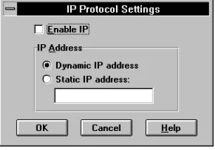
[image:34.612.282.435.100.207.2]The IP Protocol Settings dialog lets you configure the use of IP over the connection. When you click on the [IP Protocol Settings] button, a dialog similar to the following appears:
Figure 4: IP Protocol Settings Dialog
FastLink II gives you two choices as to how your IP address gets assigned:
You can request a dynamic IP address for your PC each time you connect. This IP address will be based on how the Remote Annex server is configured.
You can specify a static IP address. This IP address will be used each time you connect.To request that a dynamic IP address be assigned to you when you connect:
1 Check the Enable IP box.
2 Check the Dynamic IP address button.
To request to use a static IP address when you connect:
1 Check the Enable IP box.
2 Check the Static IP address button.
3 Highlight the Address field and enter a valid IP address in the format xxx.xxx.xxx.xxx, where xxx is a value between 0 and 255.
Static IP Address
To configure your IP stack with a static IP address, you also need to provide the Remote Annex server’s IP address (as a gateway) and the IP subnet mask. When configuring FastLink II’s IP Protocol Settings, enter the same static IP address in the Static IP address field.
Dynamic IP Address
To configure your IP stack to use a dynamic IP address, you need to specify RARP (Reverse Address Resolution Protocol), BOOTP, or DHCP (Dynamic Host Configuration Protocol). FastLink II will automatically provide the negotiated IP address to the IP stack when a RARP or BOOTP request is made. When configuring FastLink II’s IP Protocol Settings, select Dynamic IP address.
NOTE: If you use DHCP, ensure that you have a DHCP server on your network.
IP Stack Configuration
FastLink II uses ETHERNET_II for its default frame type. Do not change this frame type in the NET.CFG file or FastLink II will not work with IP.
There are numerous interfaces available to communicate between TCP/IP stacks and the ODI driver. Some stacks use the ODI interface directly, while others require a “shim” which converts calls from another interface, such as a packet driver, to the ODI driver.
NOTE: Refer to your IP stack vendor’s documentation for how to load TSRs and modify your
system files. See the FastLink II IPSTACKS.HLP help file for the latest information on IP stack configuration with FastLink II.
Adding a Connection
To add a new connection:
1 Press [Add] and enter a name for the new connection when prompted.
The new connection is displayed, and its settings are initialized based on the previously-selected connection.
2 Edit any of the individual settings.
Removing a Connection
To remove a connection from the list:
1 Highlight the Connection drop-down box, and select the connection you’d like to remove.
2 Press [Remove] to remove the connection from the list.
Connecting to a Server
Before you connect, be sure that:
You have set the connection settings correctly for dialing the Remote Annex server.
You have set the correct configuration and preferences in the Setup dialog.
You have loaded all the required drivers, such as LSL.COM and FLODI.COM.Refer to either of the chapters “Connecting From DOS” or “Connecting From Windows” below for complete information on how to set up your system in general prior to connecting.
To make the connection:
1 Be sure the Connection Status line at the bottom of the screen indicates “Idle.” If not, Press
[Disconnect] to cancel any previous connection or connection-in-progress.
2 Highlight the Connection drop-down box, and select the appropriate connection.
3 Press [Connect].
FastLink II activates the modem and dials the server. Once the phone link is created between the two modems, FastLink II and the server exchange the information necessary to establish the connection.
If all goes well, after a few seconds the connection is established.
The Connection Status line at the bottom of the screen lets you monitor the progress of the connection.
The following table describes the information returned in the message box:
Item
Description
Modem reports ...
If your modem returned a CONNECT string, it will be
displayed along with the speed of the modem-to-modem
connection over the telephone line in bits/second.
(NOTE: some modems may only display the baud rate
between the PC and modem.)
Baud rate ...
Displays the baud rate between your PC and modem.
This is the same baud rate entered in the Setup dialog.
Connected to...
Displays the name of the server to which you are
connected, and your authenticated user name.
IPX Address:
If a valid IPX connection has been established, this
message will display the connection’s IPX address.
Local IP Address:
If a valid IP connection has been established, this
message displays the connection’s IP address.
(NOTE: if you have requested a client-assigned IP
address, make sure that the reported address matches it
or your IP connection may not work.)
Remote IP Address:
If a valid IP connection has been established, this
message displays the IP address of the remote server
(or gateway) to which you are connected.
The Connection Information File
If you need to refer to the information displayed in the message box at a later time, simply view the CONNECT.TXT file in the FastLink II directory.
This file is created each time you make a new connection and contains a copy of the message box strings. You can also view the date and time of the CONNECT.TXT file to determine when the connection was started.
The Connection Failure Message
If your attempt to connect to the server was unsuccessful, an error message appears, indicating the reason that the connection couldn’t be established. For example, the server’s phone number might have been busy, or you may have entered the wrong user name or password and failed authentication.
[image:38.612.237.481.228.307.2]The following shows a typical error message:
Figure 5: Connection Failure Message Box
If you have repeated or unexplained connection failures, see Appendix A “FastLink II Connection Errors” for recommended actions.
Disconnecting
Terminal Mode
Terminal Mode provides a full-screen display that permits you to monitor FastLink II’s interaction with the modem, and lets you type directly into the modem as well. You might use Terminal Mode for the following reasons:
To view modem result strings
To diagnose modem problems
To operate the modem directly if necessary
To communicate with a communications server or security device that requires you to enter information before allowing a connection.You enter Terminal Mode from the Connections dialog by choosing [Terminal]. Once in Terminal Mode, any text you type on the keyboard is sent directly to the modem, and any text returned or echoed from the modem appears on the terminal display.
While in Terminal Mode you can:
Press [Connect] to dial the server and make a connection.
Press [Disconnect] to break the current connection.
Press [Close] to return to the Connections dialog.NOTE: You cannot use [Esc] to return from Terminal Mode. [Esc] is treated as a text character and is sent to the modem.
The Setup Dialog
The Setup dialog lets you specify configuration information and preferences. The Setup dialog lets you:
To display the Setup dialog, check the Setup button at the left of the screen. A dialog similar to the following appears:
Figure 6: Windows Client Setup Dialog
You can now edit any of the items shown. When you are through editing, press [Save] to make your changes permanent.
Port Settings
The Port Settings let you specify the brand of modem you are using and the settings for the serial connection between the PC and modem.
To specify the port settings:
1 Highlight the Modem drop-down box and select a modem from the list.
Serial Port
Your PC and modem communicate with each other over a serial port. A PC may have up to four serial ports, labeled COM1 through COM4. Either your modem is connected to one of these ports by cable, or you have an internal modem with a built-in serial port. In either case, you need to select the correct serial port for FastLink II to operate.
For the Serial Port, you may choose any of the available COM ports on your PC, or you may choose Custom. If you select one of the standard COM ports, FastLink II automatically enters information in the Port address and Interrupt (IRQ) fields. However, if your serial port has a non-standard configuration, you should select Custom and set Port address and Interrupt (IRQ) to the correct values for your serial port.
To specify the serial port to which your modem is attached:
1 Highlight the Serial Port drop-down box, and select a serial port from the list. You can choose any available COM port, or you can select Custom.
2 If you selected Custom, highlight the Port address field and enter the correct value.
3 If you selected Custom, highlight the Interrupt (IRQ) field and enter the correct value.
Automatic Redial
Every once in a while, the connection between your modem and the server’s modem may break. This could be because the phone line goes down, or it could be the result of modem errors.
FastLink II can automatically detect the dropped line, redial the server, and re-establish the broken connection. Usually, once a connection is re-established you should be able to use the network as before — any interrupted operation will usually just pick up where it left off.
Three parameters control how FastLink II tries to re-establish a broken connection:
Number of redial tries — The maximum number of redial attempts FastLink II will make in case it gets a Busy signal. You can set this value to 0 to turn off redial entirely.
Seconds to wait before redial — The time to wait before the first redial. This gives the server time to realize that the connection is broken and hang up its phone.
Seconds between redials — Determines the frequency of redial attempts after getting busy signals. To configure FastLink II’s automatic redial settings:
1 Highlight the Number of redial tries field and enter the desired value. Enter 0 if you do not want FastLink II to redial at all.
2 Highlight the Seconds to wait before redial field and enter the desired value.
Node Address
Every workstation on the network has a unique node address (also known as the MAC or Media Access Control address). This node address is used as your IPX node address if you selected client-assigned IPX address.
When you first install FastLink II, it will automatically generate a random node address for you. We recommend
that you use the node address that you get upon installation. However, you can change the value if you like.
To specify a node address directly:
Enter the new address into the Node Address field. This address is entered as 12 hexadecimal characters (0 through 9, A through F) to represent the 48-bit node address.To generate a random node address:
The Modems Dialog
The Modems dialog lets you maintain FastLink II’s list of available modems and edit their settings. From the Modems dialog you can:
Add a modem to the list of available modems
Remove a modem from the list of available modems
Edit the settings for any modemFastLink II comes preconfigured with a list of the modems you are most likely to encounter. The settings for each modem consist of a set of strings that FastLink II will use to operate that modem.
In most cases, you will not need to use the Modems dialog. All you’ll need to do is select the appropriate modem in the Setup dialog and you’ll be up and running without any trouble. Even if your modem does not appear in the list, there is likely to be another modem in the list that works the same way as yours.
[image:43.612.158.493.269.474.2]To display the Modems dialog, check the Modems button at the left of the screen. A dialog similar to the following appears:
How FastLink II Operates the Modem
FastLink II operates a modem based on the command string and result string settings for that modem:
A command string is a string sent to the modem to cause it to perform an operation, such as to reset itself, dial a number, or wait for a call.
A result string is a string sent back from the modem to indicate the result of an operation.When FastLink II initiates a call to a server, it first sends three command strings in succession: Reset, Init, and Additional. It then sends the Dial string, followed by the phone number.
The Auto-answer string is only used for dialback. After making the initial connection, FastLink II hangs up, sends the Reset, Init, and Additional strings, then sends the Auto-answer string to await the return phone call from the server.
Command Strings
The modem command strings should perform functions as follows:
The Reset string resets the modem to the factory defaults.
The Init string should:−− Configure error-correction and compression
−− Enable hardware flow control
−− Enable CD (Carrier Detect) high on connection
−− Enable hang-up on DTR (Data Terminal Ready) low.
−− Set the CONNECT report string to the modem’s DCE speed. This will show the true speed of the connection.
Response Strings
The modem response strings have the following meanings:
The OK string is returned by the modem to indicate success. Ordinarily, this string is set to OK.
The Connect string is returned by the modem to indicate a successful connection. Ordinarily, thisstring is set to CONNECT.
The Busy string is returned by the modem to indicate a busy phone line. Ordinarily, this string is set to BUSY.
The No carrier string is returned by the modem to indicate it did not get an answer. Ordinarily, this string is set to NO CARRIER.
The No dialtone string is returned by the modem to indicate it did not get a dialtone. Ordinarily, this string is set to NO DIALTONE.
The Error string is returned by the modem to indicate some other error occurred. Ordinarily, this string is set to ERROR.Adding a Modem
When adding a modem to the list, you can save yourself a little time by first selecting a modem similar to the one you want to add. The strings for your new modem will be initialized from the currently displayed strings, and you’ll have less editing to do.
To add a modem to the list of modems:
1 Press [Add] and enter a name for the new modem when prompted.
The new modem will be added to the list, and its settings (based on the previously selected modem) are displayed.
2 Highlight each of the strings you’d like to change, and edit them to your liking.
3 Press [Save] to make your changes permanent.
Removing a Modem
To remove a modem from the list:
1 Highlight the Modem name drop-down box, and select the modem you’d like to remove.
2 Press [Remove] to remove the modem from the list.
Editing Modem Settings
To edit a modem’s command or result strings:
1 Highlight the Modem name drop-down box, and select the modem whose settings you’d like to edit.
2 Highlight each of the strings you’d like to change, and edit it to your liking.
3 Press [Save] to make your changes permanent.
The Scripts Dialog
The Scripts dialog lets you create and edit scripts, which are used when you create FastLink II connections in the Connections dialog. Scripts allow you to easily automate connections to a Remote Annex server with front-end security.
NOTE: The Scripts dialog must be created from the Windows version of the FastLink II interface; that is, from FLINKW.EXE run in Windows. In addition, scripting will only work
while you are running in Windows.
From the Scripts dialog you can:
Add a script to the list of available scripts
Remove a script from the list of available scriptsFastLink II comes preconfigured with a Standard script, which works for many terminal servers and Internet access providers.
[image:47.612.158.493.106.310.2]To display the Scripts dialog, check the Scripts button at the left of the screen. A dialog similar to the following appears:
Figure 8: Scripts Dialog
Adding a Script
To add a new script:
1 Press [Add] and enter a name for the new script when prompted.
The new script will be added to the list, and the Script window will display the end of script
---line
2 Create a new script by adding script commands. See the section “Editing Scripts” below for a description of how script commands work.
3 Press [Save] to make your changes permanent.
Removing a Script
To remove a script from the list:
1 Highlight the Script Name drop-down box, and select the script you’d like to remove.
2 Press [Remove] to remove the script from the list.
Editing Scripts
You can edit the selected script using the buttons to the right of the Script Window:
To insert a new script command, highlight the line at which you'd like to insert the new command, then press [Ins].
To append a command to the end of the list, position the highlight to the ---end of script --- line, then press [Ins].
To modify an existing script command, highlight the command and press [Edit], or double-click the command line.
To remove a command from the script, highlight the command line and press [Del]
To move a command up or down in the script's execution order, highlight the command and click the up or down arrow buttons( and )
When you press [Ins] or [Edit] to insert or edit a command, the Script Command dialog will appear. This dialog allows you to select a command and enter additional information required by the command, such as an argument and options settings.
For example, if you selected expect, entered “Login:” as the String, and checked the nocase option, you would see the following display:
Figure 9: Script Command Dialog
When you press [OK], the command, argument, and option settings are formulated into a single script line and placed in the script.
Script Commands
The following script commands can be inserted into your list:
Script Command
Description
expect [-nocase]
string
Wait until string appears in the receive stream,
then proceed.
If -nocase is specified, then upper and lower
case letters are treated equally when scanning
for string; otherwise, an exact match to string is
required.
prompt [-secret]
string
Display a message with string as a prompt, and
wait for a reply. Your input will be stored as
response (see senditem below). If -secret is
specified, asterisks are echoed.
NOTE: If you press [Cancel] during your input,
the script is aborted.
senditem [-noreturn]
item
Transmit item over the channel. A carriage
return is automatically appended to string, unless
-noreturn is specified.
The item can be any of the following:
response: the last response to a prompt
username: the username field from the current
connection
password: the password field from the current
connection, or the response to a password
prompt (if you selected Prompt for Password)
wait
time
Wait until the specified time has elapsed. The
time argument is entered as seconds, up to 3
decimal places.
timeout
time
Sets the script to fail with a timeout message if
time elapses from the point at which this
command is encountered. The time argument is
entered as seconds, up to 3 decimal places.
When the script first starts, a timeout of 120
seconds (2 minutes) is used. The timeout
command overrides any previous timeout.
The time during which a PROMPT command is
waiting for input is not included in the timeout
period.
To view the Port Statistics display, check the Port Statistics button at the left of the screen. A display similar to the following appears:
Figure 10: FastLink II Statistics Screen
Statistic
Meaning
Character Driver Statistics
Rx total
Total number of characters received
Rx errors
Number of hardware receive errors (UART overrun
or framing error). If the ratio of Rx errors to Rx total
is worse than 1 in 10,000, consider reducing your
baud rate.
Rx buffer overruns
The number of times the receive buffer could not
accept additional data. Indicates a cabling problem
or modem not responding to hardware flow control.
Rx flow off
The number of times that hardware flow control was
used to throttle receive data from the modem.
Tx total
Total number of characters transmitted
Packet Statistics
Total packets sent
Total number of packets sent.
Total packets received
Total number of packets received.
Checksum errors
The number of packets with invalid checksum,
indicating a data error.
Send packet too small
The number of send packets smaller than the
minimum size.
Send packet too big
The number of send packets larger than the
maximum size.
No ECB available
The number of packets received for which no
application was listening. (This is not necessarily an
error condition.)
Receive packet overflow
The number of packets received for which no
internal buffer is available.
Housekeeping
The Housekeeping dialog has additional functionality that you can use.
The Comm Port Test option displays a list of available serial ports and determines the UART type for each.NOTE: The Comm Port Test must be performed from the DOS version of the FastLink II interface; that is, from FLINK.EXE run from the DOS command line. This is because this test must access hardware directly; this is best done when Windows is not running.
To bring up the Housekeeping menu, select Housekeeping from the FastLink II User Interface main menu.
[image:53.612.144.520.202.433.2]The resulting display will look like this:
The Comm Port Test
The Comm Port Test displays information about the serial ports that are available on your PC. To display this information:
1 From the main menu, select Housekeeping.
2 From the Housekeeping menu, select Comm Port Test.
FastLink II surveys your serial ports and display the following information about each:
The COM port number
The port’s I/O address
The type of UART (Universal Asynchronous Receiver-Transmitter) used. [image:54.612.178.552.240.470.2]FLINK.EXE Command Line Options
The FLINK.EXE command (the FastLink II DOS User Interface) offers several command line options that let you:
Connect and disconnect without running the full-screen interface.
Run the Comm Port Test option without running the full-screen interface.
Specify monochrome rather than color operation, to improve the appearance of the full-screen interface on certain gray-scale displays.Connecting from the DOS Command Line
To connect without running the full-screen interface, just specify the name of the connection right on the command line:
FLINK connectionname ↵↵
For example, if you’ve created a connection called BRANCHOFFICE, you can connect to it by typing:
FLINK BRANCHOFFICE ↵↵
Once the connection is established, information such as connection speed, data handling options, server name, and the like will be displayed on screen.
Disconnecting from the Command Line
To disconnect without running the full-screen interface use the /D switch:
Running the Comm Port Test
To run the Comm Port Test from the command line, use the /T switch:
FLINK /T ↵↵
Information about your serial ports will be displayed on screen.
Displaying Port Statistics from the Command Line
To display FastLink II statistics from the DOS command line, use the /S switch:
FLINK /S ↵↵
Complete Port Statistics information will be dumped to your screen, one line at a time. If you want to capture statistics to a file, you can direct the FLINK output to a file. For example, to write your statistics to file STATS.TXT you would type:
FLINK /S > STATS.TXT ↵↵
Using Monochrome Mode
The FastLink II User Interface automatically adjusts to whether your display adapter is color or monochrome. However, many laptops have gray-scale displays that represent different colors with various shades of gray. Sometimes the result is that some have inadequate contrast or are indistinguishable from each other.
If you find such problems when you run the FastLink II User Interface, try specifying monochrome mode using the /M switch:
FLINK /M ↵↵
Connecting from the Windows Command Line
To connect from Windows without running the full interface, just specify the name of the connection right on the command line:
FLINKW connectionname
For example, if you’ve created a connection called BRANCHOFFICE, you can connect to it as follows:
FLINKW BRANCHOFFICE
Disconnecting from the Command Line
To disconnect without running the full interface, just specify the /D switch:
FLINKW /D ↵↵
Automatic Program or Batch File Launch
When you run the FastLink II User Interface with a connection name on the command line, you can also specify one or more programs to launch once the connection has been established.
The program or programs you wish to launch must be separated by the vertical bar character (“|”). Following each vertical bar you may have a command line to launch a Windows or DOS program:
FLINKW connectionname | command1 [ | command2 ... ]
For example, to make a connection using connection name MYOFFICE, and then to run PROXY to remotely control a PC called MYPC:
FLINKW MYOFFICE | PROXY MYPC
Macros for automatic program launch
Since you can string several command lines together to perform multiple operations from the FLINKW.EXE command line, it is possible for the FLINKW.EXE command line to become too long. The macro capability provides a way around this problem.
Macros are defined in the [AppNames] section of FLINK.INI. To create a macro, you must edit this file to add an entry in the form:
macro=commandline
For example, to create a macro called RC to run PROXY to remotely control a PC named MYPC, you would include the following within the [AppNames] section of FLINK.INI:
Then, you can use the macro rather than the PROXY command line after the vertical bar in the FLINKW command line:
FLINKW MYOFFICE | RC
FLINK.INI Settings
Parameter
Meaning
ConnectNotify
For command line connections only. Set to 0 (disable)
or 1 (enable). If enabled, displays a message box with the
full connection information (name, connection speed,
whether compression or encryption were used, etc.). If
disabled, no message is displayed and no confirmation is
necessary.
DisconnectNotify
For command line connections only. Set to 0 (disable)
or 1 (enable). If enabled, displays a message box when
FastLink II is disconnected with the /D option. If disabled,
no message box is displayed.
SuccessAction
Determines what to do with the FastLink II client if a
successful connection is made from the user interface or
the command line. The default (0) is to have FLINKW
remain active in both cases.
For command line connections, set SuccessAction to:
1 FLINKW is minimized as an icon
2 FLINKW will terminate
For user interface connections, add to SuccessAction:
10 FLINKW is minimized as an icon
20 FLINKW will terminate
Note that the command line and user interface options
are additive, e.g., if you set SuccessAction=21 then
FLINKW will terminate after a successful UI connection,
and minimize after a successful command line
connection.
SuccessAction operations occur after any application
launching and message box displays (e.g., if
ConnectNotify=1).
ConnectText
For all connections. Determines whether the
II-3 Connecting from DOS
Overview
This chapter describes how to connect to the network from the DOS environment. It covers not only FastLink II, but also the other TSRs and programs you need to build an IPX stack and login to NetWare file servers. You’ll find out:
How to issue a series of commands at the DOS prompt to build an IPX stack, connect to a Remote Annex server, then login to file servers.
How to automate the above sequence using a batch file.
How to use a local login script to speed up the login process.
How to tear down your remote connection, either by issuing commands from the DOS prompt or by running a batch file.
How to use the optional FLCACHE TSR to guard against accidentally running DOS programs from the network when you’d prefer to run them from your local hard disk.Before you Connect
Before you connect make sure that:
You are not already connected to a LAN through a direct Ethernet or Token Ring connection.
You have the latest version of either NETX or VLM.Making a Connection Manually
What follows is a step-by-step