warwick.ac.uk/lib-publications
A Thesis Submitted for the Degree of PhD at the University of Warwick
Permanent WRAP URL:
http://wrap.warwick.ac.uk/110545/
Copyright and reuse:
This thesis is made available online and is protected by original copyright.
Please scroll down to view the document itself.
Please refer to the repository record for this item for information to help you to cite it.
Our policy information is available from the repository home page.
PERFORMANCE EVALUATION AND DEVELOPMENT OF
A SYNCHRO - DRIVE MOBILE ROBOT
By
CHARLES NNONYELUM J. NWUFOH, M.Sc
A thesis submitted in fulfilment of the requirements for the degree of Doctor of Philosophy in Engineering
ABSTRACT
The work described in this thesis is concerned with the
performance of the mechanical system of a mobile robot that is
capable of omnidirectional motion. The main attribute of such
mobile robots is that their direction of motion is independent of
chassis orientation. This attribute endows them with exceptional
manoeuvrability, but it is also found to pose substantial
problems by changing the level of accuracy and stability of the robot as its direction of travel changes.
The main objective of the research is to conduct a detailed evaluation of the performance of a mobile robot which is capable of omnidirectional movement achieved by means of a synchronized all-wheel steering and all-wheel drive (Synchro-drive) technique. The objective is met by comparing the synchro-drive method with
other configurations used for mobile robots, by comparing
different designs of the synchro-drive method and by analyzing synchro-drive mechanical behaviour in response to drive and
steering inputs. A kinematic model of the synchro-drive
arrangement is formulated and this is used to analyze different designs and to assess the limits of the control variables beyond which a Synchro-Drive Mobile Robot (SDMR) operation will become
unstable. A new version of the synchro-drive arrangement was
developed and was used to perform extensive practical testing in order to determine factors affecting positional accuracy and the trajectory actually executed by the mobile robot.
The analysis of the boundaries of the control space revealed the limits on acceleration which may be allowed by the robot's
control system for it to remain stable. It also showed that the
acceleration limits depend on the angle between the wheel heading and the chassis orientation, which is defined as the robot's
posture. Practical experimentation identified the major influences on robot accuracy and also related the form, magnitude
and direction of these errors to the robot's posture. The
experiments revealed that the errors were due partly to aspects of the design itself and partly due to inevitable errors in the
complete mechanical system. A continuous position error
correction method is proposed which uses experimental data as the
basis for correction. Correction quantities vary with posture,
and the method uses a modification to the steering rate to minimize trajectory error.
ACKNOWLEDGEMENT
I wish to express my deep felt gratitude to my supervisor Dr.
T.C. Goodhead for his motivation, enthusiasm and encouragement.
He is also thanked for his advice and support in every aspect
that made this research possible. My special thanks go to Dr.
S.A.G Chandler and Dr. E.L. Hines both of whom provided
substantial advice and support.
Acknowledgment is given to Prof. S.K. Bhattacharyya for his
support, which made it possible for this project to be completed.
My thanks go to Mr. G.J. Robinson whose experience and patience
was very valuable in the construction of the mobile robot. And
also to Mr. D.G. Thompson for his interest and attention he gave
to the project, and all other members of engineering workshop
staff who contributed to the construction of the mobile robots.
Finally I would like to thank Mr. M. Stevens who assisted in the
development of the control system for the mobile robot.
I am grateful to Drs. J.C. & M. Nduaguba, Mr. & Mrs. V.C. Nwufoh,
and other members of my family and friends for their advice,
moral and financial support throughout the period of this
project. May God bless you all.
I do accept the responsibility for any error in presentation and
typing of this thesis.
CONTENTS
ABSTRACT
ACKNOWLEDGEMENT
DEDICATION
CHAPTER 1 !
INTRODUCTION 1
1.1 DESCRIPTION OF A WHEELED MOBILE ROBOT. 1
1.2 RESEARCH MOTIVATION. 2
1.3 RESEARCH SPECIFICATION. 3
1.4 RESEARCH OBJECTIVES. 5
CHAPTER 2 8
LITERATURE SURVEY 8
2.1 LOCOMOTION SYSTEMS. 8
2.1.1 LEG LOCOMOTION SYSTEMS. 8
2.1.2 TRACK LOCOMOTION SYSTEMS. 11
2.1.3 WHEEL LOCOMOTION SYSTEMS. 12
2.1.3.1 BASIS OF DISTINCTION BETWEEN WHEEL
MOBILE ROBOTS. 13
2.1.3.2 DIFFERENT WHEELED MOBILE ROBOT'S
KINEMATIC CONFIGURATION. 16
2.2 OMNIDIRECTIONAL MOTION. 27
2.2.1 COMPOUND WHEEL BASED DESIGNS. 29
2.2.1.1 ILONATOR OR MECANUM WHEEL. 29
2.2.1.2 WHEEL COMPRISING OF ROLLER DRUMS. 33
2.2.1.3 ADVANTAGES AND DISADVANTAGES OF
COMPOUND WHEEL. 34
2.2.2 CONVENTIONAL WHEEL SYNCHRO-DRIVE (ALL
2.2.3 DESIGNS OF SYNCHRO-DRIVE MOBILE ROBOT
(SDMR). 39
2.2.3.1 WHEEL ASSEMBLY, WITH WHEEL-OFFSET
FROM THE STEERING AXIS (TYPE-1). 44
2.2.3.2 WHEEL ASSEMBLY, WITH DIFFERENTIAL
GEAR COUPLED WHEEL SET (TYPE-2). 45
2.2.3.3 WHEEL ASSEMBLY, WITH WHEEL-SET ON
STEERING AXIS (TYPE-3). 46
2.3 TRANSMISSION SYSTEM. 47
CHAPTER 3 52
ANALYSIS OF FACTORS THAT INFLUENCE PERFORMANCE 52
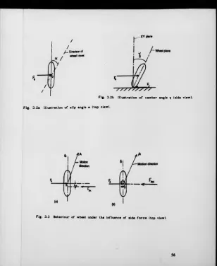
3.1 WHEEL FORCE/TORQUE ANALYSIS. 52
3.1.1 COMPONENT FORCES, MOMENTS AND ANGLE
OF A WHEEL. 52
3.1.2 SDMR WHEEL. 57
3.2 ERRORS THAT AFFECTS THE SDMR PERFORMANCE. 61
3.2.1 TYPES OF ERROR. 61
3.2.1.1 PREDICTABLE ERRORS. 61
3.2.1.2 NON-PREDICTABLE ERRORS. 64
3.2.2 SOURCES OF ERROR. 66
3.2.2.1 POWER TRANSMISSION MECHANISM. 66
3.2.2.2 TYRE. 68
3.2.2.3 WHEEL ALIGNMENT. 69
3.2.2.4 NATURE OF FLOOR SURFACE (ROUGHNESS). 69
3.2.2.5 SENSORS AND COMPUTATION. 69
3.3 SDMR BEHAVIOUR. 70
3.3.1 BEHAVIOUR UNDER DRIVE INPUT ONLY. 70
3.3.1.1 EQUATIONS OF MOTION AND TRAJECTORY
ANALYSIS. 71
3.3.2 BEHAVIOUR UNDER A STEERING INPUT. 79
3.3.2.1 STEADY-STATE BEHAVIOUR. 80
3.3.2.2 TRANSIENT STATE BEHAVIOUR. 83
3.3.2.3 DIRECTIONAL STABILITY. 88
CHAPTER 4 94
KINEMATIC MODELING AND BOUNDARIES OF CONTROL SPACE 94
4.1 SYNCHRO-DRIVE MOBILE ROBOT *S (SDMR's) KINEMATICS. 95
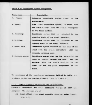
4.1.1 COORDINATE SYSTEM ASSIGNMENT. 98
4.1.2 SDMR KINEMATIC VELOCITIES AND
ACCELERATIONS. 99
4.1.2.1 WHEEL-OFFSET FROM WHEEL ASSEMBLY
STEERING AXIS (TYPE-1). 101
4.1.2.2 WHEEL-SET ON WHEEL ASSEMBLY STEERING
AXIS (TYPE-3:A). 103
4.1.2.3 WHEEL-SET ON WHEEL ASSEMBLY STEERING
AXIS WITH MECHANICAL COMPENSATOR UNIT
(TYPE-3:B). 104
4.2 BOUNDARIES OF THE CONTROL SPACE. 108
4.2.1 NO SLIPPING CONDITION. 110
4.2.2 NO OVERTURNING CONDITION. 121
CHAPTER 5 128
PROTOTYPE DEVELOPMENT AND FURTHER ANALYSIS OF
5.1 PROTOTYPE DEVELOPMENT. 128
5.1.1 STRUCTURE AND LAYOUT OF THE PROTOTYPE
SDMR. 128
5.1.2 METHODS TO COMPENSATE WHEEL ASSEMBLY
DESIGN-ERROR. 135
5.1.2.1 SOFTWARE COMPENSATION. 137
5.1.2.2 HARDWARE COMPENSATION. 137
5.2 THE IMPACT OF WHEEL FORCES/TORQUE AND STEERING
INPUT ON SDMR PERFORMANCE. 140
CHAPTER 6 149
EXPERIMENTAL TECHNIQUE TO DETERMINE SDMR ERRORS
AND BEHAVIOUR 149
6.1 EXPERIMENTAL OBJECTIVES. 149
6.2 EXPERIMENTAL PROCEDURE. 150
6.2.1 TESTS CONDUCTED. 151
6.2.2 METHODS USED TO RECORD PATHS AND SET
THE SDMR STATES. 157
6.2.3 MEASUREMENTS TAKEN AND EQUIPMENT USED. 160
CHAPTER 7 i 6 6
EXPERIMENTAL RESULTS 166
7.1 TEST RESULTS WITH VERSION 1 SDMR. 170
7.1.1 DETERMINATION OF LATERAL ERROR (5y) ,
LONGITUDINAL ERROR (6x) , AND ARC RADIUS (R). 178
7.1.2 STATISTICAL ANALYSIS. 181
7.2 TEST RESULTS WITH VERSION 2 SDMR. 185
7.2.1 TEST RESULTS WITH THE SDMR OPERATING IN
THE NORMAL STATE (CATEGORY A) . 186
7.2.1.1 STATISTICAL ANALYSIS. 193
7.2.2 TEST RESULTS IN WHICH THE SDMR WHEELS
BARES UNEVEN LOAD (CATEGORY B ) . 196
7.2.3 TEST RESULTS WITH WHEEL NUMBERED 1
MISALIGNED (CATEGORY C ) . 204
7.2.4 TEST RESULTS WITH TWO WHEELS MISALIGNED
INWARDLY TOWARDS THE CENTRE OF MASS
(CATEGORY D). 209
7.2.5 TEST RESULTS WITH TWO WHEELS MISALIGNED
OUTWARDLY FROM THE CENTRE OF MASS
(CATEGORY E). 214
7.2.6 TEST RESULTS WITH ONE WHEEL HAVING
A SMALLER RADIUS (CATEGORY F). 218
7.2.7 COMBINED RESULTS. 222
7.2.8 RESULTS SUMMARY. 231
CHAPTER 8 235
DISCUSSION OF RESULTS 235
8.1 RESULTS DISCUSSIONS. 237
8.2 MAIN DIFFERENCES BETWEEN SDMR CONFIGURATION
AND CONVENTIONAL MOBILE ROBOT CONFIGURATION
WHEN OPERATING IN AN ERROR STATE. 248
8.3 FORMULATION OF POSITION ERROR CORRECTION METHOD. 252
CHAPTER 9 263
CONCLUSIONS AND RECOMMENDATIONS FOR FURTHER WORK 263
9.1 CONCLUSIONS. 263
9.2 RECOMMENDATIONS FOR FURTHER WORK. 272
APPENDIX A 275
RESEARCH PUBLICATIONS 275
A.2 AGV CONTROL USING AN INTELLIGENT ENVIRONMENT
APPROACH (IEA). 287
APPENDIX B 298
B.l STEERING SYSTEM ACCELERATION REQUIREMENT. 298
B.1.1 FOR A DIFFERENTIAL DESIGN. 301
B.1.2 FOR A TRICYCLE DESIGN. 302
B.l.3 FOR A SDMR DESIGN. 302
B. 2 EFFECT OF MECHANICAL ERRORS. 303
APPENDIX C 306
SYNCHRO-DRIVE MOBILE ROBOT (SDMR) SPECIFICATIONS 306
C. l FIRST PROTOTYPE. 306
C.2 SECOND PROTOTYPE. 308
REFERENCES. 310
CHAPTER 1
INTRODUCTION
This chapter considers the area within the robotics field on
which the research is centred, the factors that motivated the
study, the specification of the research, and the overall
objectives.
1.1 DESCRIPTION OF A WHEELED MOBILE ROBOT.
This research is centred on the mobility aspects of mobile
robots. A mobile robot is considered to be a machine that is
capable of being programmed to move around within its environment
and does not necessarily carry a manipulator. In particular this
work deals with robots that achieve their mobility through the
use of wheels and it is not concerned with mobility achieved
using other methods such as legs or tracks. For the purpose of
focusing the study, the following operational definition of a
'wheeled mobile robot' is adopted;
'A wheeled mobile robot is a reprogrammable machine capable
of locomotion by means of the forces created at the contact
between the wheels and the ground'.
Mobility is provided by means of drive and steering power inputs
to the wheels. The transmission of power to enable movement is
achieved through a series of links and joints. These links and
joints are classified as, higher-pair, closed-chain joints
1.2 RESEARCH MOTIVATION.
The motivation for this research is to identify and evaluate
wheeled mobile robot mechanical designs which provides the
minimum constraint to robot mobility and provides improved
performance over existing designs. Much of the mobile robot
research investigation documented concentrates on the application
of the mobile 'platform' as a testbed to study artificial
intelligence [Moravec'83], [Nilsson'84], [Giralt'85]. The
investigation of the capabilities of the mobile platform
mechanisms in order to assess the limits that it can impose on
the overall task have mostly been neglected. The concentration
of efforts into investigation of intelligence stems from the
widely held opinion that accuracy and manoeuvrability of the
platform itself do not contribute greatly to the overall
performance of the mobile robot. Such schools of thought believe
that software can compensate for any deficiency in the platform.
Assumptions of this sort have proved very costly in many projects
[Holland'8 6].
Improved mechanical system designs affecting mobility, and better
understanding of the control requirements will enable the
rethinking of some of the present approaches to intelligent
system development. For example, if a mobile robot senses that
it has encountered an obstacle, even if it knows how to avoid it,
it may not be possible to avoid the obstacle if it does not have
the desired manoeuvrability and accuracy, irrespective of the
knowledge of the situation.
In this thesis the foundation for the design and development of a
high performance mechanism for wheeled mobile robots is laid.
This is achieved through kinematic modeling, performance analysis
and feasibility study.
1.3 RESEARCH SPECIFICATION.
It was considered necessary at the outset to define the type of
mobile robot for which the mechanical system was to be the basis
of study. Despite the fact that robots are generally defined as
multi-functional machines and therefore able to perform a variety
of tasks, it has to be accepted that mechanical hardware always
imposes limitations on the potential application areas. For a
mobile robot the major factor influencing the design is the type
of terrain over which the robot must travel.
It was decided that the research would consider terrains of the
type found in man-made environments such as industrial and
commercial buildings and their immediate surroundings. The main
type of surface encountered in man-made environments is
relatively hard, smooth and quite flat. Mobility occurs mostly
in a horizontal two-dimensional (2D)plane, although steps and
stairs are common place. It was decided at this stage to
restrict movement to the 2D plane as the addition of a step
climbing capability adds considerable complexity to any
mechanical design [Knasel'8 6] and there are many applications
where a robot capable of moving only in 2D can use ramps and
Within most man-made environments there are space limitations.
There are also a huge range of possible paths that the mobile
robot may be required to execute. Ideally the robot should be
able to execute any path that is required of it and should be
able to access any space that is physically large enough to
accept it.
The particular class of wheeled mobile robot that are of major
interest in this research are those capable of omnidirectional
motion. Omnidirectional motion allows a mobile robot to move
from rest along a vector at any angle to its current heading.
Consideration is given to other arrangements such as the
differentially steered type and tricycle type. In the
omnidirectional motion class a variety of designs exist, but the
study will concentrate on a design which uses all-wheel steering
and all-wheel drive. In this design the wheels are always driven
and steered in synchronization, and the mobile robots constructed
using this design are referred to in this thesis as Synchro-Drive
Mobile Robots (SDMRs).
The concept of synchro-drive for mobile robots is not new and has
been implemented in a number of cases, the most notable being the
Cybermation K2 [Holland'8 6] which is a commercially available
product. However no detailed analysis of the design of SDMR's
and no evaluation of the design features which affect their
performance could be found. In particular it was considered that
one feature associated with the design of the wheel assemblies
could substantially improve the robots' performance capabilities.
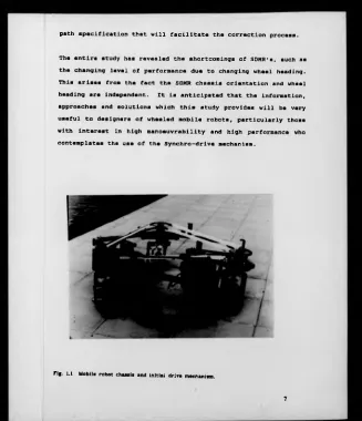
In order to evaluate the performance of a new design of wheel
assembly two SDMR's were built (Fig. 1.1 shows the first SDMR at
the initial stage of this study) and experiments were conducted
to establish the factors influencing performance of such design
and the behaviour of SDMRs in general. In addition to the
influence of the mechanical system, the relationship between the
control system and the mechanical system was studied and the
means of finding the limits of the control input variables to
ensure stable operation was established.
1.4 RESEARCH OBJECTIVES.
This research study has five main objectives, which comprises of;
> Investigating ways of achieving omnidirectional motion.
> Analysis of Synchro-Drive Mobile Robot (SDMR) mechanical
system behaviour,
> Kinematic modeling of the SDMR,
> Establishing the control boundaries for stable operation.
> Experimental testing, qualitative and quantitative analysis
of test results to create better understanding of the
factors that influence performance.
Performance criteria of SDMRs are considered in the light of;
position error comprising of lateral and longitudinal error,
chassis precession, systems stability and nature of the
In view of the research motives, specification and objectives, a
detailed review of mobile robots was conducted, with particular
reference to those capable of omnidirectional motion (chapter 2).
In analyzing SDMR behaviour, factors that influence performance
are highlighted and considered (chapter 3). Such factors as the
interaction between the SDMR and its environment, sources of
mechanical system errors, and the way the SDMR responds to drive
and steering inputs.
Kinematic modeling considerations (chapter 4) have created a new
method of modeling SDMR's based on the constraints which they
experience. Through kinematic modeling detailed theoretical
comparisons of different SDMR designs have been achieved. The
modeling of SDMR's and the need to determine the basic control
system requirements have provided the means to establish the
SDMR control space (chapter 4). This is the space within which
the SDMR operation is stable (i.e. no slipping or overturning).
Practical experimental testing and statistical analysis are used
to assess performance and feasibility of two functional prototype
SDMRs. Tests conducted with the two prototypes gave a detailed
insight into the physical operation of SDMR's and the
characteristics which they possess. It created the understanding
for the formulation of a new method of position error correction.
This method uses the experimental results to determine parameters
that will form part of the control system and also the nature of
path specification that will facilitate the correction process.
The entire study has revealed the shortcomings of SDMR's, such as
the changing level of performance due to changing wheel heading.
This arises from the fact the SDMR chassis orientation and wheel
heading are independent. It is anticipated that the information,
approaches and solutions which this study provides will be very
useful to designers of wheeled mobile robots, particularly those
with interest in high manoeuvrability and high performance who
contemplates the use of the Synchro-drive mechanism.
[image:18.373.16.343.6.386.2]CHAPTER 2
LITERATURE SURVEY
In this chapter, means of achieving locomotion is briefly
discussed. The different configurations of wheeled mobile robots
are reviewed on the basis of their operations, benefits and
limitations. Methods of achieving omnidirectional motion by
wheeled mobile robots which enables them to be highly
manoeuvrable are considered in greater detail. Also discussed
briefly are methods of power transmission
2.1 LOCOMOTION SYSTEMS.
Mobile robots can achieve mobility using different types of
locomotion systems such as legs, tracks and wheels. Within these
different locomotion types there are also various designs. Some
of the designs and concepts are discussed in this chapter.
2.1.1 LEG LOCOMOTION SYSTEMS.
Mobile robots with legged locomotion are of varying degrees of
complexity, the most technically challenging being the two
anthropomorphic multi-jointed legs (biped). Well-known research
institutes in this area include; MIT in USA, Waseda University,
University of Tokyo, and Hitachi all in Japan, Cardiff and
Edinburgh Universities in UK. Other leg systems are the four
(see Fig. 2.1), six and eight leg types, which are the areas that
tend to have received most attention to date, because balancing is
much easier and mobility can be achieved with less complex leg
"«■ *< Structure or f=ur-,w robot
[image:20.370.22.331.10.371.2]structure [Knasel'8 6]. With more than two legs the mobile robot
can easily manoeuvre in difficult terrain.
Mobile robots with legs have high mobility and adaptability.
These can be achieved by using coordinated control of its
multi-degrees of freedom. For example the biped walking robot
developed by Hitachi has a configuration similar to the leg and
hip structure of a human being. Each leg has six mechanical
joints allowing motion in 12 degrees of freedom. The joints are
controlled by hydraulic actuators. The hydraulic unit actuates
the joints through the conversion of electrical energy into
hydraulic energy [N-Nagy'8 6].
Walking robots are still at the prototype stages, with the
multi-legged ones (those with more than two legs) showing greater
potential at present. A parallelogram linked spider-like device
is now commercially available through Odetics corporation in the
USA [Knasel'8 6]. On the whole mobile robots that use legs to
produce locomotion suffer from: low speed even on flat surface,
static and dynamic instability, complicated control system, and
high energy consumption.
On hard, flat smooth surfaces such as found in most man-made
environments, the limitations stated above are serious,
particularly the inability to achieve moderate speeds on flat
surfaces. They are also limited by their ability to carry a
payload. However the result of research in this area will be
very useful for applications where the terrain is less hospitable
such as space exploration, agriculture and locations where debris
obstructs an otherwise flat floor.
There is one reported instance where attempts are being made to
bring legged mobile robots into factories. In this approach it
is envisaged that a special path can be made for the mobile
robots. The path, which is known as 'born floor' [Knasel'8 6], is
a magnetic platform. The 'born floor' allows attachment of the
feet and makes it possible to achieve walking without the need to
tackle balancing problems. This approach though novel, lacks
both path flexibility and speed. The feasibility of this
approach in a manufacturing environment, where there is high
demand on flexibility and speed cannot be envisaged.
2.1.2 TRACK LOCOMOTION SYSTEMS.
Mobile robots that use tracks to achieve locomotion have the
ability to translate across rough terrain. They have little
problem in terms of dynamic stability. With a sophisticated
track mechanism and control system, relatively moderate speed can
be achieved over most terrains [Fujie'85], [Knasel'8 6].
For instance in the mobile robot been developed by Fuji, et al
[Fujie'85], tracks are mounted on both sides of the robots' body,
and each track runs on main, sub and planet wheels (see Fig.
2.2). Rough terrain capability is enhanced by varying the
movement of the planet wheels. Another example is the one
developed by The Belgium Atomic Energy Agency. This uses three
using the main track, while inclined obstacles are mounted using
the auxiliaries [Knasel'8 6]. It is being developed for use in
nuclear reactors.
Research in this area is directed mainly towards outdoor or rough
terrain applications, such as in construction sites and nuclear
reactors. Tracked locomotion systems suffer from: low speed,
high energy consumption caused mainly by the dead load and also
poor accuracy because of 'skid steering'. Considering these
drawbacks track locomotion system are not seen as an attractive
means of achieving mobility for a mobile robot that will be used
in the majority of industrial and commercial applications.
2.1.3 WHEEL LOCOMOTION SYSTEMS.
Locomotion systems employing wheels have received the greatest
attention among the three forms of locomotion under
consideration. The interest was created mainly because of its
benefits that easily met man's initial need for long distance
transportation of goods. The benefits of wheeled locomotion
system are as follows: On flat surfaces, they are highly energy
efficient [Bekker'69], they are capable of high speeds, and they
can make use of simple control systems.
The above mentioned benefits of wheeled locomotion system not
withstanding, they still suffers some set-backs, such as: limited
terrain mobility and wheel slippage problems.
Due to the limitations of the different basic forms of locomotion
systems; research is on-going to try to develop hybrid locomotion
mechanisms. The leading researchers in this area are the
Japanese [Knasel'8 6], [N-Nagy'8 6]. An example is the one
developed by Mitsubishi Heavy Industries whose locomotion system
makes use of wheels and legs. On a flat surface it tucks in the
legs, making use of the wheels to traverse. When climbing stairs
the legs are used. For an intermediate obstacle a combination of
both are used and in an idle state it puts the wheels at the end
of the legs (Knasel'8 6]. Mitsubishi Electric in a similar
interest has extended the work further by developing what they
call Multifunctional Robotic Vehicle (MRV-3). It uses four track
segments as either legs or tracks depending on the prevailing
circumstance. The motivation for the research in this area
arises from the construction industry and maintenance work in
nuclear reactors (or other unstructured environment).
For environments that are characterized by hard, smooth, flat
surfaces with a requirement for load carrying and moderate speed
of goods delivery, the wheel locomotion system appears more
appropriate. It is therefore selected as the basis for this
work.
2.1.3.1 BASIS OF DISTINCTION BETWEEN WHEELED MOBILE ROBOTS.
This review of wheeled locomotion system is performed mainly on
the basis of difference in 'steering and drive systems' , but not
on factors such as number of wheels. The importance and effect
of number of wheels on issues such as steering behaviours and
the locomotion method. The majority of existing mobile robots
have either three wheels or four wheels, though some have u p to
six wheels, such as the Terragator [Wallace'85].
Those based on three wheels tend to benefit from the design of
simpler wheel assemblies, and the absence of a spring or
spring-damper element to provide suspension. However they suffer
from the fact that their wheel's contact with the ground are
nearer the centre of mass than other geometries (such as
rectangular) for a given mobile robot size, and can run into
tipping stability problems.
Those based on four wheels generally have better tipping
stability. But they suffer from the need for spring suspension
to ensure continuous wheel/floor contact, due to four points of
ground contact. More wheels means greater power requirements and
also an increase in manufacturing cost. With the four wheel
design a tipping stability problem may arise if there is a change
of load position that causes excessive change in the centre of
mass.
Mobile robots can also be distinguished by the type of wheel
used. The choice of wheel is mostly influenced by terrain
[Chun'87]. The emphasis in most of the literature is not on
wheel types but on the ways in which they may be configured. The
existence of different novel types of wheels is noted [Chun'87],
[Wright'87]. Some of these wheel types (see Figs. 2.3a - 2.3d)
are the conventional wheel, compound or omnidirectional wheel,
(b) Compound or Omnidirectional wheel [Chun'87).
(c) Ball wheel [Chun'87]. (d) Wire wheel (Chun’87).
ball wheel and wire wheel. Amongst the categories the ball type
is highly manoeuvrable without any form of steering or slipping.
However it has severe limitations for operation in an autonomous
mode because it is very difficult to control. Within the limits
of the search conducted, no literature reveals its implementation
to date. The approach is at present only a concept [Wright'87].
Consideration of its workability however indicates that it will
be extremely difficult to achieve high level of accuracy in both
position and directional control.
2.1.3.2 DIFFERENT WHEELED MOBILE ROBOT'S KINEMATIC CONFIGURATION
Their are several types of mobile robot Kinematic configuration.
The most prominent ones are:
(a) The Differential steering configuration,
(b) The Tricycle or Swivel bolster configuration,
(c) Axle pivot or Ackerman steering configuration,
(d) All-wheel Drive/Steering or Synchro-drive configuration,
(•) Compound wheel based or Mecanum or Ilonator types.
(a) Differential steering configuration.
The differential steering configuration type is the most commonly
documented and used type among the above configurations. This
stems from its simple geometric and kinematic configuration
(Muir'8 6]. Here two parallel conventional wheels of identical
radius are placed on each side of the mobile robot (see Fig. 2.4a
to 2.4c). The mobile robot can translate to any destination by
driving the wheels at the same speed, resulting in straight line
motion, or at different speeds, resulting in motion in a curve
(b) Traveling through a curve path.
arc. Most of the mobile robots of this category uses one or two
idler (or castor) wheels for static stability. In the
differential configuration category the commonly known mobile
robots includes; Yamabico [Kanayama'85], Shakey (Nilsson'84],
Hilare [Giralt'79].
With the differential configuration one cannot execute a small
radius turn without considerable reduction in drive speed. This
is because of the way it achieves turning, which involves
reduction of the forward speed of one wheel, and in some cases
reversal of direction. Hence with this configuration, a slight
modification to its path of travel may not be possible without
stopping the mobile robot, and this extends journey times, causes
expenditure of energy in regaining momentum and hinders smooth
motion.
This configuration requires only drive input necessary to control
the two motors that drive the wheels. There is no requirement
for steering input, and hence mobile robot's theoretical
trajectory can be easily determined as a function of the two
wheel speeds [Tsumura'81].
(b) Tricycle configuration.
The remaining mobile robot configurations are kinematically more
complex, in varying degrees, when compared to the differential.
The tricycle configuration is the case where the mobile robot has
three wheels, with a front wheel that can be steered and driven,
while the two rear wheels are undriven and of fixed parallel
orientation (see Fig. 2.5). Such is the case with Neptune
[Ponder'84], and Hero- 1 [Helmers'83).
Due to the fact that only the speed and heading of the front
wheel is controlled, the actual trajectory taken by the mobile
robot is not readily predicted, since it is influenced by the two
fixed rear wheels. The test conducted by Nelson [Nelson '89)
shows that the accuracy of the path taken by the mobile robot
depends on the location of the fixed wheels with respect to the
centre of gravity.
(c) Ackerman steering configuration.
The Axle pivot or Ackerman steering configuration (see Fig. 2.6)
comprises of four wheels, two of w h i c h are parallel and opposite
one another but coupled together through an Ackerman linkage and
they generally serve as the front wheels. The other two are
fixed and are parallel to one another. The linkage in the two
front wheels is to ensure approximately correct angle turn on
both wheels when steering, which avoids wheel slip [Muir'8 6].
The wheels may or may not be driven. In the Stanford Cart
[Moravec'83] type, the wheels are not driven. The wheels can
however be independently driven. For example the JPL Rover
[Lewis'73] has two sets of ackerman steering wheels, with all the
wheels independently driven. However they don't have to be
independently driven, because they c a n use a differential unit to
allow for difference in distance travelled by the wheels during a
Dnva/steenng whcd
□
...
Turning radius
H f. 2.5 Illustration of Tricycl. confiriration.
The axle pivot configuration is similar to that used in most
motor cars. When compared to the differential and tricycle
configuration its mechanism is more complicated.
The tricycle and Ackerman steering wheel configurations both have
quite severe turning angle restriction (see Figs. 2.5 and 2.6).
And their efficiency in mobility is directionally dependent.
That is they do not exhibit the same behaviour in both forward
and backward movement.
(d) All-wheel Drive/Steering or Synchro-Drive configuration.
The all-wheel steering configuration as the name implies is a
configuration that allows all wheels of a mobile robot to be
steered. It can be called a synchro-drive system when it is
steered and driven in unison. This configuration achieves motion
that gives maximum manoeuvrability on a horizontal plane
[Moravec'83]. Such motion is considered 'omnidirectional'
[Moravec'83], [Nakano'81].
All-wheel steering only provides omnidirectional motion when all
the wheels turn the same direction by the same amount at the same
speed, and when steering is possible through a complete 360°.
The term all-wheel steering has been applied to cars which have
the back wheels steered through very limited angles in opposite
direction for better manoeuvrability or in the same direction for
better stability at high speed. However they achieves lateral
translation through very limited angles and are not capable of
Omnidirectional motion allows a mobile robot to move from rest
along a vector at any angle to its current heading (see Figs.
2.5a - 2.5d). With such motion capability a wheeled mobile robot
can therefore move between any two points in a plane without
restriction. Omnidirectional motion makes a mobile robot's
heading independent of its orientation (see Figs. 2.7a - 2.7c)
(Appendix A.l); and this can provide substantial benefits as well
as several problems.
Mobile robots with an all-wheel drive/steering configuration are
not original and have already been built. They include the ODV
(Omni-Directional Vehicle) built by MITI in Japan [Arai'81],
[Nakano'83], the CMU Rover also known as Pluto [Moravec'83], the
Kludge, and its successor Cybermation K2A [Holland'8 6] and the
Denning both of which are now commercial available. Most of the
present designs rely on shaft transmission (Holland'8 6],
[Nakano'83]. The Kludge which is an earlier version used chain
transmission while the K2A uses twin concentric shafts. There
are some based on belt drive like that from Barry [Barry'89] and
RWI company that are also commercially available. Further details
of different designs of the synchro-drive configuration are given
later.
Figs. 2.7 Basic omnidirectional motion:
(a) Longitudinal translation.
(b) Lateral translation.
(c) Diagonal (heading) translation.
(d) Omnidirectional mobile robot’s degree of freedom -
(e) Compound wheel type.
In the compound wheel type, the means to provide steering lies
essentially in the wheel. Compound wheels either have a central
hub with rollers arranged at the periphery (commonly known as
either the Ilonator [Ilon'73] wheel or the Mecanum [Jonsson'85]
wheel (see Figs. 2.8a - 2.8c above)); or are without a wheel hub
but only made of roller drums [Rose'89) (see Fig. 2.8d).
The compound wheels are held in a fixed relation to one another
and they are capable of being independently driven. By driving
the wheels in varying combination of speeds and directions, a
resultant force is produced which makes it possible to drive the
vehicle in any desired direction from 0° to 360° (i.e.,
Omnidirectionally). Uranus [Muir'87] and others
[Carlisle'83], [Jonsson'85], [van der Loos'8 6] are examples of
mobile robots that are based on the compound wheel. Further
details of compound wheel mobile robot operation is given later.
In summary, table 2 . 1 shows different types of steering
configuration and the types of motion they can achieve. The
mobility limitation of the conventionally steered wheeled mobile
robots can be attributed to their inability to move
[image:36.375.21.347.8.377.2]Tabic 2.1. Steering eonfisuraupn. mgiipn and turning rcsinflipna
Sieenng
configuration
Motion T vpes Turning
Radius
Restnction
1
Loneitudunal Lateral Diagonal
(any angle) Reverse
Swivel Bolster
steenng
y
v / X
X
X
(US
Axle Pivot
steenng
V
y
X
X
X
Dual Swivel
Bolster steering
V
V xX
X
X 1
C m 3
Differentialsieenng
y
v / X
X
y
(S_£>
All-wheelsteenng
y
V
y
y
y
llonator
wheel
- 3 y
y
3
i
1x0
2.2 OMNIDIRECTIONAL MOTION.
Omnidirectional motion allows a mobile robot to move from rest
along a vector at any angle to its current heading (see Fig.
2.7d). It also provides the ability to translate in any
direction on a horizontal plane without any associated rotation
of the chassis.
The benefits of this type of motion are substantial and are
described as follows:
(a) Removal of mobile robot orientation constraints on the
path planning algorithms - this results in maximum
manoeuvrability which is particularly important to achieve
movement in confined spaces.
(b) Elimination of the need to rotate and control mobile
robot chassis orientation during motion, in order to travel along
a specified path - this results in an ability to respond to a
change in direction rapidly.
(c) Elimination of the need to reduce speed during turns
except to comply with stability and wheel slip constraints - this
results in reduced time to complete a set of moves and allows
smooth motion even along complex routes.
(d) There is no path restriction because of zero turning
radius - any path can be executed provided that kinematic and
dynamic constraints are not violated.
(d) High manoeuvrability allows more scope for the design of
larger mobile robots - this is as a result of efficient use of
turning space; unlike, for example, the tricycle configuration
There are however a number of problems associated with the
provision of omnidirectional motion. These arise from a
fundamental inability to rotate the chassis and they are:
(a) The lack of a constant relationship between the position
of the wheels and the direction of travel.
(b) Problem of identifying a specific part of the mobile
robot as the 'front' for sensor mounting, etc.
(c) Inability to arrive at a destination in a specified
orientation.
(d) Inability to orientate an object or device carried on the
mobile robot with respect to its environment.
When implementing a mobile robot capable of omnidirectional
motion, items b, c and d can be overcome by the use of an
additional platform capable of independent rotation about a
vertical axis relative to the chassis.
However, the variability of the wheel positions with respect to
the direction of travel cannot be eliminated and this gives rise
to different characteristics with regard to stability and
accuracy. There is no published work identifying the effect of
stability and accuracy characteristics which vary with heading
and it was therefore investigated in detail as part of this work.
Two configurations have been identified as capable of producing
omnidirectional motion. A further discussion of the
2.2.1 COMPOUND WHEEL BASED DESIGNS.
As mentioned earlier there are two main types of compound wheel,
namely;
(i) Wheel having rollers at the periphery (Ilonator or
Mecanum wheel) of the wheel hub.
(ii) Wheel comprising of roller drums without wheel hub.
2.2.1.1 ILONATOR OR MECANUM WHEEL.
The major difference between mobile robots using the Ilonator
wheel are primarily;
> the peripheral roller material, and
> the arrangement of the rollers on the periphery (see Fig.
2.8a - 2.8c ) .
Attempts have been made to actuate the rollers by using a highly
sophisticated driving arrangement [Muir'8 6], but the complexity
of such an approach has resulted in it not being feasible in
practice.
The wheel on which the mobile robot is based is provided with
rollers that rotate freely about their axis, at an acute angle to
the wheel axis. The roller angle varies from 30° to 90°. In
most designs the rollers are identical, but they can be made of
different sizes (see Fig. 2.8a). In the Unimation wheel design
[Carlisle'83] use is made of eight rollers, comprising of
alternating long and short ones. In this design the rollers axes
are at 90° to the main wheel axis. The design helps to reduce
produces an intermediate state when ground contact is transferred
from one roller to the next.
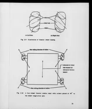
Operation of Ilonator Wheeled Mobile Robot.
If the rollers' mounting angle is not 90*, their axes can be
inclined either side of the normal, which makes the wheel to be
considered as either 'left-bias' or 'right-bias' (see Fig. 2.9).
The biasing indicates the direction in which the mobile robot can
freely move based on the roller's angle, with only the roller
rotation. For a forward or reverse movement of the wheel, the
wheel behaves like a conventional wheel.
The way in which a mobile robot, based on the Ilonator wheel
achieves different forms of motion can be analyzed by using Figs.
2.10 and 2.11. Fig. 2.10 shows a four-wheeled arrangement of a
mobile robot, with the rollers axes displaced at 45* to the wheel
hub longitudinal axis.
For a forward or reverse movement of the mobile robot (i.e., 0 =
0°), only the wheels will turn. That is, there will not be any
spinning of the rollers on their axes. And for 0 - 45°, the
wheel hub ceases to turn leaving only the rollers in contact with
the ground to spin freely on their axes. Thus for an angle 0
which is neither 0* n o r 45° the mobile robot movement is achieved
[image:41.374.21.342.8.379.2]by a combination of rotation of the rollers and the wheel hub
[Daniel'85].
Fig. 2.9 Illustration of Ilonator wheel biasing.
Fig. 2.10 A four-wheel Ilonator mobile robot with rollers placed at 45* to
[image:42.372.24.341.6.381.2]Flt . 2.12 Diagram showing the component
Iionator wheel mobile robot.
■*0
I
~SB
o —
-€ 1
• S c<b) Lateral motion
# = ^ = 0 °
T
$
"H i l c
(d) Rotational mouon
a four-wheel design.
velocities and v2 of an
By resolving the Ilonator wheel velocity into two components,
having them directed along the line of 0 — 0° and 0 = 45* (see
Fig. 2.12 above), moving the wheel in any direction 0 can be
achieved by a combination of motion along these component
vectors. The kinematics for the control are defined on the basis
of the transformation of the mobile robot's velocities (i.e.,
translation and rotation velocities) into the wheel velocities
[Daniel'85], [Muir'8 6].
2.2.1.2 WHEEL COMPRISING OF ROLLER DRUMS.
Mobile bases have been developed by making use of wheels made of
roller drums [Rose'83]. Such a wheel is shown in Fig. 2.13. Its
motion analysis is similar to that of Ilonator wheel. Hence
there is no further discussion on its operation.
Fig. 2.13 Roller drums arrangement showing driven and free rolling
2.2.1.3 ADVANTAGES AND DISADVANTAGES OF COMPOUND WHEEL.
The compound wheel has its advantages and disadvantages.
The advantages being that:
(a) Based on the roller's freedom to rotate of their own
accord along their axes, compound wheels suffers none of the
excessive frictional force suffered by conventional wheel which
is caused by constant steering required to achieve change in
heading [Carlisle'83].
(b) Because of smaller frictional force influences on the
wheel during motion, there is minimum wear of both the rollers
and floor surface.
Their disadvantages include:
(a) With compound wheels, the mobile robot tend to 'bounce'
as the contact point of the wheel with floor translates
discretely from o n e roller to the next roller. The extent of
this effect is dependent on the distance between two adjacent
rollers along the periphery of the wheel, but it can never be
completely eliminated.
(b) The operation of an Ilonator wheeled mobile robot
requires continuous close monitoring and control of speed on all
the wheels, if it is to achieve a small tracking error. This
requirement brings the need for a precisely engineered wheel and
a complex control algorithm.
(c) It has poor tolerance to surface irregularities, which is
as a result of the effect of the peripheral rollers. This also
influences their directional stability and efficiency.
(d) In an experiment carried out by Daniel, D.J. et al
[Daniel'85], on a mobile robot based on the compound wheel, the
following are some of the results that were obtained:
o Power requirement is dependent on direction of travel,
o Most power is required for mobile robot lateral travel,
indicating that roller bearing friction is greatest in the
lateral direction of travel; and in most cases all the wheel
motors are actuated.
o Due to t h e fact that individual motors are required for each
wheel, and they are in some cases driving against each other,
its power consumption is generally high,
o Even w i t h servo braking incorporated there still exists
substantial movement after braking, caused by the roller
slippage.
(e) Control is achieved by transforming the mobile robots'
velocities to that required by the respective wheels and rollers.
Difficulties arise due to the inability to know the precise
amount of dr i v e motion occurring at the rollers.
(f) Additionally the wheel is considerably more expensive to
manufacture tha n that of a conventional wheel.
2.2.2 CONVENTIONAL WHEEL SYNCHRO-DRIVE (ALL-WHEEL DRIVE/
STEERING) CONFIGURATION.
Due to the significant benefits in omnidirectional motion, and
the basic simplicity in the fundamental design that achieves such
a motion through all-wheel steering, it has attracted the
interest of man y researchers particularly in the United States
Omnidirectional translation coupled with rotation is only
possible if a means of adjusting the relative alignment of
individual wheels is provided. But the speed of the drive wheels
also must be adjusted to avoid slip, except in the unique case of
pure rotation about the mobile robot's own axis of symmetry.
These three forms of motion are represented in Figs. 2.14a -
2.14c. An all-wheel drive and steer mobile robot capable of
chassis rotation as well as omnidirectional translation must
therefore have independent control of the drive and steering of
each wheel rather than permanent synchronization. A three wheel
mobile robot of this type has been built at CMU [Moravec'83], but
the control of the three drive motors and three steering motors
to ensure smooth path tracking has proved very difficult and is
not considered in practice to offer advantage over a mobile robot
with a separate orientable platform.
One of the attributes of the synchro-drive system is its fixed
orientation as the mobile robot changes direction. This property
of synchro-drive can serve the same purpose as a gyroscope for
its directional reference [Holland'8 6]. Like a gyroscope, such a
mobile robot under any mechanical systems error is liable to
suffer from precession.
To reduce precession the following factors are crucial: mobile
robot symmetry must be maintained; steering transmission system
must have minimal backlash; wheels must be accurately aligned;
wheel diameters have to be the same and tyre materials should
offer identical frictional coefficients.
lb)
Figs. 2.14 All-wheel steering system:
(a) All wheels aligned: Omnidirectional translation.
(b) Relative misalignment of the wheels; Omnidirectional
translation and rotation.
One of the benefits of the synchro-drive system is that only two
motors can be used to provide independent drive torque and
steering torque for the wheels. The vector forces of the wheels
are in principle in a permanent state of parallelism. This
allows it to have good directional stability even on undulating
surfaces. A mobile robot whose design is based on Synchro-Drive,
using conventional wheels tends to have lower energy consumption,
higher mobility efficiency and less control complexity, when
compared to that of a compound wheel arrangement.
This research work is centred on the Synchro-Drive configuration,
for two major reasons. These are:
(1) Synchro-drive appears to have a good combination of the
performance characteristics considered desirable in a mobile
robot, these being :
» Manoeuvrability
t> Accuracy
> Energy efficiency
> Ease of control
> Directional stability
(2) Reported work on Synchro-Drive Mobile Robots (SDMR) lacks
detailed analysis of its performance particularly with regards to
accuracy, stability and the demand on the control system. It is
generally assumed to have good accuracy and good directional
stability even with simple control. Therefore there is need to
test and validate such accepted notions.
For the above two reasons the rest of this thesis is concentrated
on evaluation of mobile robot designs that achieves
omnidirectional locomotion through the Synchro-Drive mechanism.
2.2.3 DESIGNS OF SYNCHRO-DRIVE MOBILE ROBOT (SDMR) .
The synchro-drive technigue is not very popular among researchers
working in the field of mobile robotics because most have simply
employed the most readily available platform as a means of
investigating issues in navigation and autonomous intelligent
decision making. But varying types of synchro-drive
configurations that have been implemented are depicted in Figs.
2.15 - 2.18. Differences exist between these designs in the
areas such as; transmission system, wheel assembly, location of
drive and steering motors, and techniques employed in
reducing/eliminating inherent design drawbacks.
As there are differences in designs, so there are in performance.
Each of the above factors affect; mechanical complexity, control
complexity, energy efficiency, and production cost. For
instance, the design shown in Fig. 2.18 can achieve different
motion modes, namely; omnidirectional mode, car mode and rotation
mode mechanically by use of clutch engagement [Arai'81]. The
multi-mode mobile robots so far built are research machines and
intended to display the attributes of each mode. It is the
authors view that modes other than omnidirectional are
unnecessary and the reasons can be seen in Appendix A.l. In this
work the mobile robot was designed to be operational in only the
omnidirectional mode, and the objective was to investigate the
Fig. 2.1
Fig. 2.
Differential wheel assembly design [Moravec’831.
Investigation revealed that there are three major ways in which a
conventional wheel assembly can be configured, in order to
achieve omnidirectional motion. They are as follows:
(i) Wheel-offset from the steering axis of the wheel assembly
(see Fig. 2.19), referred to as Type-1.
(ii) Differential gear coupled wheel set (see Fig. 2.20),
referred to as Type-2.
(iii) Wheel-set on the steering axis of the wheel assembly (see
Fig. 2.21), referred to as Type-3.
rotation axis
Fig. 2.19 Illustration of design of the wheel-offset from the wheel
assembly vertical axis (Type-1).
Drive shaft
Fig. 2 .20 Illustration of design of the differential coupled wheel set
(Type-2).
Fig. 2.21 Illustration of design of the wheel-set on the wheel assembly
2.2.3.1 WHEEL ASSEMBLY, WITH WHEEL-OFFSET FROM THE STEERING
AXIS (TYPE-1).
Type-1 has been implemented by some researchers [Nakano'81],
[Holland'8 6] (see Figs. 2.16 and 2.18) working on an
omnidirectional mobile robot. The schematic illustration of such
a technique is shown in Fig. 2.19.
One of the main benefits of the technique is that by offsetting
the tyre/floor contact point from the vertical axis of wheel
assembly rotation, the wheel can in theory rotate o n its own axis
without any slip or 'scuffing' occurring at the floor contact
when turning. Using Fig. 2.19 it can be shown tha t if a correct
offset distance r{ is used and all other factors remain correct,
the wheel assembly has the tendency to spin about t h e point where
the wheel assembly vertical axis intersects the floor, instead of
round a small circle.
In this arrangement the wheel radius ra is a function of the
offset distance r , for a given gear ratio. That is;
ra - Crt (2.1)
where,
£, is the gear ratio given by,
C - n2/nt (see Fig. 2.19).
The wheel radius dependency on the offset distance is a source of
limitation for such technique, in that a wheel w ith radius other
than that on which the design was based cannot easily be used.
rotation of the wheel assembly and therefore increases the
potential for errors. Also the assumption is made that the tyre
makes a line contact with the ground which is fixed relative to
the steering axis. Tyres must therefore be very narrow and stiff
to resist lateral deflection.
Another drawback is that offsetting the wheel from the steering
axis increases the tendency for the wheel to steer when a drive
motion is initiated. The effect of the drawback can be limited
by making use of a worm gear set, which has a self-locking
function [Arai'81]. The worm gear locks the steering subsystem
when there is no power supply from its motor (the same locking
effect takes place in the drive subsystem). The closer the worm
gear arrangement is to the wheel the more effective will be the
resistance to induced steering.
2.2.3.2 WHEEL ASSEMBLY, WITH DIFFERENTIAL GEAR COUPLED WHEEL
SET (TYPE-2).
This wheel configuration technique has been implemented by
researchers in USA [Moravec'83] (see Fig. 2.17). In this
technique a differential gear unit is placed directly under the
vertical axis of rotation of the wheel assembly (steering axis),
with two wheels coupled to the two ends of the differential gear
unit (see Fig. 2.20). The two parallel placed wheels at the ends
of the differential gear allows steering of the wheel with a low
frictional force even when stationary, and the symmetry of the
In this configuration the mobile robot direction of travel is the
resultant of the angle of the heading of the individual wheel
assemblies. Forward and backward motion is achieved only if the
drive shaft is rotated by the steering action; so one requires a
separate drive motor for each wheel. Forward and backward
movement is achieved by turning the inner shaft (drive shaft) .
While turning the outer shaft (steering shaft) (see Fig. 2.20)
steers the wheel assembly, with the two wheels rolling in small
circles [Noravec'83].
This technique generally produces a mobile robot with wheel
assembly that is mechanically complex, expensive, and requiring a
complex control system [Moravec'83], [Muir'8 6] with lower energy
efficiency.
2.2.3.3 WHEEL ASSEMBLY, WITH WHEEL-SET ON STEERING AXIS (TYPE-3)
This third technique, which has the wheel located on the SDMR
steering axis, has been explored as a part of this work. From
the investigations that have been carried out at the time of
writing this thesis, there is no reported work that is
implementing this technique. The wheel assembly design is
depicted in Fig. 2.21.
By locating the tyre/floor contact point on the SDMR's wheel
assembly steering axis, the problem of the wheel having the
tendency to steer when drive motion occurs is in theory reduced.
This is because there are no offset link forces that introduces a
moment about the steering axis. But on the other hand, this
configuration introduces a tendency for the S D M R to drive when
steering motion occurs. This is caused by the coupling of the
steering and drive subsystems that allows the wheel to be both
driven and steered. Steering causes the wheel t o drive about a
small circle. The value of the drive introduced is dependent on
the wheel assembly gear ratio.
It has been discovered that the above drawback c a n be compensated
for by incorporating worm gears and a differential gear
arrangement into the drive/steering system of t h e SDMR (details
on h o w it function is presented in chapter 4 a n d 5) . Another
drawback, though not as significant, is that this technique
requires a marginally greater number of gears than the first
technique.
This configuration tends to produce a slightly higher rate of
tyre wear than the other two techniques, if t h e mobile robot
executes a turn when it is in a stationary state. Nevertheless
such a wheel assembly provides an improved stability when
compared with Type-1. This comes from two m ain sources which
are; the tyre/floor contact and the wheel assembly steering axis
have their z-axis coincidental, and there is a fixed relationship
between the mobile robot's centre of mass and the wheels contact
with the floor irrespective of the direction of travel (details
are in the chapter 4 and 5).
2.3 TRANSMISSION SYSTEM.
robot system. This is borne out of the fact that if one uses the
various transmission elements appropriately, one will achieve an
overall design, which may be: compact; reliable; eas y to maintain
and competitive both in terms of performance a n d cost. Also
gaining high power transmission efficiency; accurate and fine
movement; and suitability regarding weight and s i z e requirements
[Duggan'71].
The transmission elements that may be implemented are:
■* Belts with pulleys
■* Chains with sprockets
+ Shafts with gears.
The shaft, belt and chain transmission elements have their
respective benefits and limitations, which are presented below.
Shaft transmission elements have the following advantages: They
have definite velocity ratio. They can ach i e v e high load
application. They can operate at high speed. W i t h it a compact
design is possible [Holland'8 6].
The shaft transmission element disadvantages include: It cannot
usually be obtained as a standard component. It is not easy to
isolate or absorb shock and vibration. It requires consideration
regarding lubrication. It does not generally accept bending
deflection - gears cannot accept misalignment due to shaft
deflection [Duggan'71]. It can be difficult to minimize weight
while maintaining adequate stiffness. Unlike chai n s and belts it