warwick.ac.uk/lib-publications
A Thesis Submitted for the Degree of PhD at the University of Warwick
Permanent WRAP URL:
http://wrap.warwick.ac.uk/96043/
Copyright and reuse:
This thesis is made available online and is protected by original copyright. Please scroll down to view the document itself.
Please refer to the repository record for this item for information to help you to cite it. Our policy information is available from the repository home page.
1
Development and Characterisation of
Next Generation Stylus for Micro Coordinate
Measuring Machine
by
Mohd Anuar Bin Ismail
A thesis submitted in partial fulfilment of the requirement for the
degree of
Doctor of Philosophy in Engineering
University of Warwick, School of Engineering
In collaboration, with
National Physical Laboratory United Kingdom
4
Table of content
Table of content ______________________________________________________ 4
List of tables _________________________________________________________ 9
List of figures _______________________________________________________ 10
Acknowledgement ___________________________________________________ 18
Declaration _________________________________________________________ 19
Publications by the author _____________________________________________ 20
Abstract ____________________________________________________________ 21
Abbreviations _______________________________________________________ 22
Chapter 1: Introduction _______________________________________________ 23
1.1. Aim and motivation __________________________________________ 23 1.2. Thesis Objectives ____________________________________________ 24 1.3. Research approach ___________________________________________ 24 1.4. Thesis layout ________________________________________________ 24
Chapter 2: Background and Literature review _____________________________ 26
2.1. Introduction ________________________________________________ 26 2.2. Dimensional metrology _______________________________________ 26 2.3. Micro-CMMs ________________________________________________ 27 2.4. Probing system for micro-CMMs ________________________________ 29
2.4.1. Conventional tactile Styli for Micro CMM probing system ______________________ 30
2.4.2. Non-conventional tactile styli design of probing system for micro-CMM __________ 43
2.4.3. Summary of the review of probing systems _________________________________ 50
2.5. Manufacturing route of styli for micro-CMMs ______________________ 53
2.5.1. Focused Ion Beam technique _____________________________________________ 53
2.5.2. Wire electro discharge grinding ___________________________________________ 54
2.5.3. One-pulse electro discharge (OPED) _______________________________________ 55
2.5.4. Micro Electro-chemical machine __________________________________________ 56
2.5.5. Assembly of stylus system hybrid manufacturing technique ____________________ 57
2.5.6. Summary of the manufacturing route of micro-styli ___________________________ 58
5
2.6.1. Definition of roundness and sphericity in surface geometry ____________________ 59
2.6.2. Method of data fitting for roundness and sphericity calculation _________________ 59
2.6.3. Review on Roundness and sphericity measurement techniques on spheres________ 61
2.7. Key knowledge gap and research question ________________________ 63
Chapter 3: Design consideration of the stylus system for micro-CMMs _________ 66
3.1. Introduction ________________________________________________ 66 3.2. Geometrical consideration _____________________________________ 66
3.2.1 Background ___________________________________________________________ 66
3.2.2 Diameter of Stylus shaft and stylus tip______________________________________ 67
3.2.3 Effective length and Aspect ratio __________________________________________ 68
3.2.4 Relationship between stylus tip diameter, effective length and diameter of stylus shaft
_____________________________________________________________________ 69
3.2.5 Summary of the design rules for geometry conditions: ________________________ 71
3.3. Forces during measurement ___________________________________ 72
3.3.1 Background ___________________________________________________________ 72
3.3.2 Force during single point probing _________________________________________ 73
3.3.3 Force during scanning ___________________________________________________ 82
3.3.4 Force associates with bending or deflection of the stylus ______________________ 83
3.3.5 Summary of design rules for forces ________________________________________ 85
3.4. Physical condition ____________________________________________ 86
3.4.1 Background ___________________________________________________________ 86
3.4.2 Probing speed vs moving mass ____________________________________________ 87
3.4.3 Surface quality condition of stylus tip sphere ________________________________ 88
3.4.4 Stiffness of stylus system ________________________________________________ 89
3.4.5 Summary of design rules for physical condition ______________________________ 95
3.5. Material selection for stylus system ______________________________ 96
3.5.1 Background ___________________________________________________________ 96
3.5.2 Young’s modulus of material _____________________________________________ 97
3.5.3 Yield strength of the measured workpiece __________________________________ 98
3.5.4 Adhesive and abrasive wear ______________________________________________ 98
3.5.5 Summary of design rules for material selection ______________________________ 99
3.6. Manufacturing technique and process __________________________ 100
3.6.1 Manufacturing techniques and the effect of control parameters _______________ 100
3.6.2 Summary of design rules for manufacturing process and assembly of stylus ______ 101
6 Chapter 4: Exploration of design rule parameters using analytical models _____ 109
4.1. Introduction _______________________________________________ 109 4.2. Preliminary modelling of micro-stylus with tip diameter less than 10 µm
_________________________________________________________ 110 4.3. Analytical Modelling for mechanical properties of stylus: ____________ 112 4.4. Modelling the relationship between aspect ratio and material properties
_________________________________________________________ 119 4.5. Conclusion ________________________________________________ 122
Chapter 5: Mechanical testing of prototype styli __________________________ 124
5.1. Introduction _______________________________________________ 124 5.2. Manufacturing techniques for the test micro styli _________________ 125 5.3. Details of experimental Set-up _________________________________ 130
5.3.1. Design of stylus holder _________________________________________________ 131
5.3.2. Force sensing mechanism _______________________________________________ 131
5.3.3. Motion mechanism for the stylus ________________________________________ 132
5.3.4. Positioning, alignment and Monitoring components _________________________ 133
5.3.5. Control software ______________________________________________________ 133
5.4. Preliminary performance testing of each component _______________ 133
5.4.1. Testing of noise for precision mass balance ________________________________ 134
5.4.2. Noise level of the chromatic confocal sensor _______________________________ 135
5.4.3. Stability testing of mass balance plate _____________________________________ 137
5.4.4. Optimum parameter testing for the micro translation stage ___________________ 139
5.4.5. Initial testing/trial-run of the overall experimental set-up _____________________ 140
5.5. Procedure for the experiment to measure the stiffness of the stylus ___ 143
5.5.1. Experimental Setup. ___________________________________________________ 143
5.5.2. Positioning the stylus relative to the test-workpiece _________________________ 143
5.5.3. Trial-run of testing ____________________________________________________ 144
5.5.4. Testing procedure _____________________________________________________ 144
5.6. Procedure for measuring the maximum safe tip force ______________ 147
5.6.1. Experimental setup, positioning of stylus and initial/trial run __________________ 147
5.6.2. Testing procedure _____________________________________________________ 147
5.7. Post-measurement processing: Method of data analysis ____________ 149
5.7.1. Data processing for experiment of stiffness measurement ____________________ 150
7 5.8. Presentation and discussion of experimental results _______________ 159
5.8.1. Experimental results of stiffness measurement _____________________________ 159
5.8.2. Experimental results of maximum safe tip force measurement _________________ 170
5.9. Uncertainty evaluation of the experimental result _________________ 174
5.9.1. Uncertainty determination and analysis of stiffness measurement ______________ 175
5.9.2. Uncertainty determination and analysis of maximum safe tip force measurement _ 178
5.10.Conclusion ________________________________________________ 180
Chapter 6: Sphericity measurement of micro-spheres ______________________ 181
6.1. Introduction _______________________________________________ 181 6.2. Aspects of the measurement strategy for micro spheres ____________ 182
6.2.1. Coherence scanning interferometry ______________________________________ 184
6.2.2. Rotational Referencing technique ________________________________________ 192
6.2.3. Data fusion technique- stitching technique _________________________________ 193
6.2.4. Sphericity calculation using data fitting modelling ___________________________ 196
6.3. Measurement setup and procedure ____________________________ 196
6.3.1 Determination of measurement parameters _______________________________ 196
6.3.2 Sample preparation and handling ________________________________________ 201
6.3.3 Instrument and measurement setup ______________________________________ 201
6.3.4 Preliminary measurement and investigating the quality of measurement data ____ 202
6.3.5 Decision in selection of parameter for experiment ___________________________ 212
6.3.6 Measurement procedure _______________________________________________ 213
6.4. Post-measurement data processing- Architecture of stitching algorithm 214
6.4.1 Pre-processing – Data processing of measurement results ____________________ 215
6.4.2 Registration process ___________________________________________________ 215
6.4.3 Combination process of measured surface datasets __________________________ 219
6.4.4 Post-processing of data fusion ___________________________________________ 221
6.5. Presentation and discussion of results ___________________________ 221
6.5.1 Topography of fusion surface and result of stitched error and repeatability error __ 221
6.5.2 Resultant sphericity of the surface ________________________________________ 226
6.6. Determination of source of uncertainty in sphericity measurement ___ 228
6.6.1. Uncertainty and data reduction related to lateral distortion and optical transfer
function of the measured surface ________________________________________ 228
6.6.2. Uncertainty related to the rotation and tilting angles of surface data ____________ 229
6.6.3. Uncertainty related to the stitching algorithm-fusion technique ________________ 229
6.6.4. Uncertainty related to sphere data fitting technique in sphericity deviation calculation
8 6.7. Conclusions ________________________________________________ 230
Chapter 7: Conclusion ________________________________________________ 232
7.1. Conclusion on thesis objective and research question ______________ 232 7.2. Future works _______________________________________________ 237 7.3. General conclusion __________________________________________ 238
Bibliography _______________________________________________________ 239
Appendix A ________________________________________________________ 258
A1: Matlab code for calculation of tilting angle from the reference flat _____ 258 A2: Matlab code for translation of tilted angle and calculation of stitched error
9
List of tables
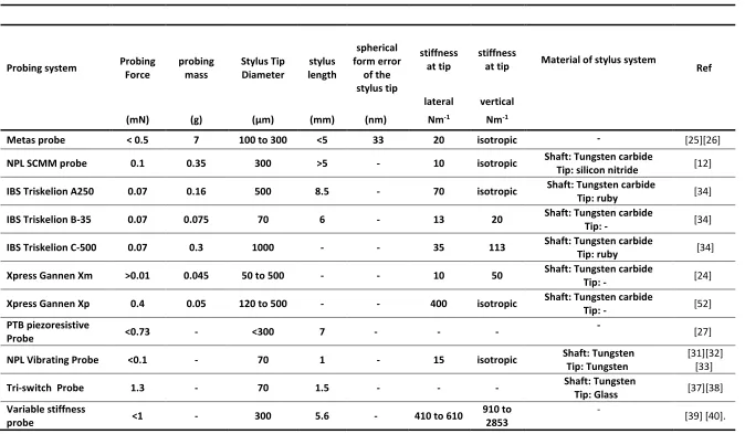
Table 2.1: summary of the parameters for the several reviewed probing systems of the micro-CMM in the category of the conventional tactile styli design. The parameter reported as (-) are either not provided by its literature or not applicable. Please note that most report do not clearly differentiate between the stiffness of the stylus system and the overall
probing system.____________________________________________________________ 52
Table 4.1: Preliminary analytical solution of stylus design model_____________________110
Table 4. 2: Analytical modelling for mechanical properties of the stylus_______________ 113
Table 4. 3: Material properties of Tungsten, Aluminium and Cast Iron [130] [131]_______119
Table 5. 1: Geometrical dimension and analytical modelling data for the micro- styli
manufactured using the variant hybrid manufacturing techniques (type1 to type4)_____ 128
Table 5. 2: The results of stiffness measurement for all styluses including the uncertainty estimation _______________________________________________________________ 160
Table 5. 3: The results of maximum safe tip force measurement for all styluses including the uncertainty estimation _____________________________________________________ 170
Table 6. 1: metrological characteristic of NPL CSI instrument (model name: Talysurft CCI HD) from latest calibration certificate_____________________________________________ 191
Table 6. 2: Summary of measurement parameter_________________________________ 212
Table 6. 3: Result of stitching error analysis for overall tilt surfaces measurement at rotation angles of 0˚, 30˚, 60˚, 90˚, 120˚ and 150˚________________________________________ 224
Table 6. 4: Result of stitching error analysis for overall rotation surfaces measurement___225
Table 6. 5: repeatability error of each location of the measurement surface dataset. These errors are calculated from surface value of root means square (RMS)(Sq parameter )
between surfaces .two repeated measurement were taken at each location ___________ 225
Table 6.6: The results of sphericity deviation using three types of sphere fitting
modelling________________________________________________________________ 227
10
List of figures
Figure 2. 1: NPL Small Volume CMM (SCMM) [11] ________________________________ 27
Figure 2. 2: Carl Zeiss F25 micro-CMM __________________________________________ 28
Figure 2. 3: Probing system according to ISO 10360-1 [18] __________________________ 29
Figure 2. 4: Construction of UMAP stylus system [20] ______________________________ 30
Figure 2. 5: NPL Capacitive Stylus [12] __________________________________________ 32
Figure 2. 6: Image of the first prototype of TUE probe (left) [22] , and it had been improved and commercialised by Xpress Precision engineering (right) [23] _____________________ 33
Figure 2. 7: image of component and construction of METAS Probing and stylus System [23] _________________________________________________________________________ 34
Figure 2. 8: Piezoresistive stylus system [28] _____________________________________ 35
Figure 2. 9 : working principle of stylus deformation [28] ___________________________ 36
Figure 2. 10: Fizeu interferometer stylus system [30] ______________________________ 37
Figure 2. 11: NPL vibrating stylus [31] __________________________________________ 38
Figure 2. 12: IBS Triskelion Ultra-Precision Touch Probe ____________________________ 39
Figure 2. 13: Differential capacitor based stylus system ____________________________ 40
Figure 2. 14: Image of the component of Tri-Switch Stylus System [28] ________________ 41
Figure 2. 15: Schematic diagram for variable stiffness probe [42] _____________________ 42
Figure 2. 16: Opto-Tactile PTB-Werth Fibre Probe [45] _____________________________ 44
Figure 2. 17: Component of the PTB-WERTH Fibre Stylus Probe [21] __________________ 44
Figure 2. 18: Laser trapping stylus system [35] ___________________________________ 45
Figure 2. 19 : Principle of standing wave scale or laser trapping [35] __________________ 46
Figure 2. 20: Standing Wave Stylus [36] _________________________________________ 47
11 Figure 2. 22: Principle of spherical capacitive plate [38] ____________________________ 48
Figure 2. 23: AE Wire Based Stylus system [39] ___________________________________ 49
Figure 2. 24: Sensing Principle of Acoustic Emission Torch stylus system [39] ___________ 49
Figure 2. 25: Uniaxial Resonant probe stylus [40] _________________________________ 50
Figure 2. 26: (a) is the basic principle of WEDG while (b) is a typical step and condition for WEDG [57] ________________________________________________________________ 54
Figure 2. 27: schematic diagram of OPED process [67] _____________________________ 55
Figure 3.1: structure of stylus system ___________________________________________68
Figure 3. 2: Aspect ratio of the measured surface and stylus ________________________ 69
Figure 3. 3: Allowable stylus deflection, Wa [51] __________________________________ 70
Figure 3.4 : Type of forces during micro-CMM measurement _______________________ 72
Figure 3. 5 : Probing Force during Single Point Probing for touch triggering force [21] ____ 73
Figure 3. 6 : Comparison between surface forces and gravitational force of the SiO2 sphere and Si surface plane [111] ____________________________________________________ 81
Figure 3. 7: Comparison between surface forces and gravitational force of the Sapphire sphere and Al surface plane [21] ______________________________________________ 81
Figure 3. 8 : Comparison between type of surface forces and gravitational force for Si sphere and gripper [109] __________________________________________________________ 82
Figure 3. 10: force in vertical direction __________________________________________ 83
Figure 3. 9: Force in the horizontal direction _____________________________________ 83
Figure 3. 11: structure of conventional design styli ________________________________ 92
Figure 3. 12: structure of tapered design of styli __________________________________ 93
Figure 3. 13: Stiffness model for the fibre probe [21] ______________________________ 93
Figure 4.1: stylus design based on the preliminary analytical design model (µm) _____ 111
Figure 4. 2: Effect of stylus tip diameter in the function of allowable probing force _____ 115
12 Figure 4. 4: Effect of stylus shaft diameter in the function of allowable probing force____ 116
Figure 4. 5: Effect of mechanical aspect ratio in the function of allowable probing force _ 116
Figure 4. 6: Effect of effective length in the function of stiffness of the stylus __________ 117
Figure 4. 7: Effect of diameter of shaft in the function of stiffness of the stylus _________ 118
Figure 4. 8: Effect of mechanical aspect ratio in the function of stiffness of the stylus ___ 118
Figure 4. 9: Behaviour of elastic deflection (Ws) and allowable stylus deflection (Wa) in the function of effective aspect ratio when stylus tip made from tungsten is contacting
measured workpiece made also from Tungsten. _________________________________ 120
Figure 4. 10: Behaviour of elastic deflection (Ws) and allowable stylus deflection (Wa) in the function of effective aspect ratio when stylus tip made from tungsten is contacting
measured workpiece made from Aluminium ___________________________________ 120
Figure 4. 11: Behaviour of elastic deflection (Ws) and allowable stylus deflection (Wa) in the function of effective aspect ratio when stylus tip made from tungsten is contacting
measured workpiece made from Cast Iron alloy _________________________________ 121
Figure 5. 1: Type 1 styli – combination of WEDG and OPED manufacturing process ___ 126
Figure 5. 2: Type 2 styli – Combination of WEDG manufacturing process for stylus shaft and commercial glass sphere for stylus tip _________________________________________ 126
Figure 5. 3: Type 3 styli – combination of WEDG and ECM process for stylus shaft and OPED for stylus tip _____________________________________________________________ 127
Figure 5. 4: Type 4 styli – smallest dimension (less than 20 µm) using ECM process and OPED ___________________________________________________________________ 127
Figure 5. 5: Schematic diagram of overall base experimental setup __________________ 130
Figure 5. 6: Engineering drawing of stylus holder ________________________________ 131
Figure 5. 7: test workpiece is placed on the precision mass balance to function as force sensing mechanism ________________________________________________________ 132
13 Figure 5. 9: Result of second run testing for noise of precision mass balance. (a) is
representing the raw measurement data point while in (b) shows its distribution. With mean of 0.06 mg, standard deviation of 0.04 mg, kurtosis of 0.7 and skewness of -0.11, the points of this data is slightly headed to the left of distribution ___________________________ 135
Figure 5. 10: The drift and noise of the chromatic confocal sensor over period of time from initially setting up _________________________________________________________ 136
Figure 5. 11: The noise behaviour of chromatic confocal sensor after it has stabilised ___ 136
Figure 5. 12: First testing result for stability of mass balance measured by chromatic confocal sensor. (a) represents a raw measurement data point while in (b) shows its
distribution. With a mean of 0.024 µm, standard deviation of 0.015 µm, kurtosis of -0.03 and skewness of 0.1, the distribution of this graph is normal with slightly have right
skewed._________________________________________________________________137
Figure 5. 13: Second testing result for stability of mass balance measured by chromatic confocal sensor. (a) represents the raw measurement data point while in (b) shows its distribution. With mean of 0.017 µm, standard deviation of 0.024 µm, kurtosis of -0.22 and skewness of -0.003, the points of this data is slightly headed to the left of distribution __ 138
Figure 5. 14: Third testing result for stability of mass balance measured by chromatic confocal sensor. (a) is representing the raw measurement data point while in (b) shows its distribution. With mean of 0.03 µm, standard deviation of 0.027 µm, kurtosis of -0.55 and skewness of 0.15, the points of this data is slightly skewed to the right of distribution ___ 138
Figure 5. 15: The result of 0.1 µm of incremental value ___________________________ 140
Figure 5. 16 : The result of 0.05 µm of incremental value __________________________ 140
Figure 5. 17: The behaviour graph of precision mass balance, manipulation stage and
precision chromatic confocal sensor in initial/trial run testing experiment ____________ 142
Figure 5. 18: The stylus tip contacted the test-workpiece in the Koverall-testing part ___ 145
Figure 5. 19: the upper region of stylus shaft was contacting the test-workpiece in
Ksetup-testing part ______________________________________________________________ 146
Figure 5. 20: condition of the broken stylus _____________________________________ 148
14 Figure 5. 22: Slope of the force-displacement graph obtained from displacement result from the precision manipulation stage is compared and verified with the displacement result obtained from the chormatic confocal sensor for stylus 0602-5-6 and correction is calculated ________________________________________________________________________ 151
Figure 5. 23: Force-displacement for stylus 0602-5-6 in Ksetup-testing experiment _____ 152
Figure 5. 24: Slope (K constant) of Force-Displacement graph for stylus 0602-5-6 in
Ksetup-testing experiment ________________________________________________________ 152
Figure 5. 25:Force-displacement for stylus 0602-5-6 in Koveral-testing experiment _____ 153
Figure 5. 26: Slope (K constant) of Force-Displacement graph for stylus 0602-5-6 in
Koveral-testing experiment ________________________________________________________ 153
Figure 5. 27: Result of Ksetup-testing experiment for the stylus 0602-5-6 _____________ 154
Figure 5. 28: Result of Koverall-testing experiment for the stylus 0602-5-6 ____________ 154
Figure 5. 29: Force-displacement graph for stylus 0506-12 type 1 experiment of maximum safe tip __________________________________________________________________ 156
Figure 5. 30: Graph of Force-displacement for stylus 0602-5-6 type 4 for experiment of maximum safe tip force ____________________________________________________ 156
Figure 5. 31: Gradient graph to observed behaviour of the slope of force-displacement graph for stylus 0506-12 manufacturing type 1 experiment of maximum safe tip ____________ 157
Figure 5. 32: Gradient graph to observed behaviour of the slope of force-displacement graph for stylus 0602-5-6 manufacturing type 4 experiment of maximum safe tip force _______ 157
Figure 5. 33: Graph of Force-displacement for stylus 0511-1-2 manufacturing technique type 2 for experiment of maximum safe tip _________________________________________ 158
Figure 5. 34: Comparison between the experimental result and the analytical modelling for stiffness of styluses of manufacturing type 1 over the mechanical aspect ratio _________ 162
Figure 5. 35: Comparison between the experimental result and the analytical modelling for stiffness of styluses of manufacturing type 1 over the effective length of stylus ________ 162
Figure 5. 36: Comparison between the experimental result and the analytical modelling for stiffness of styluses of manufacturing type 2 over the mechanical aspect ratio _________ 163
15 Figure 5. 38: Comparison between the experimental result and the analytical modelling for stiffness of styluses of manufacturing type 3 over the mechanical aspect ratio _________ 164
Figure 5. 39: Comparison between the experimental result and the analytical modelling for stiffness of styluses of manufacturing type 3 over the effective length of stylus ________ 164
Figure 5. 40: Comparison between the experimental result and the analytical modelling for stiffness of styluses of manufacturing type 4 over the mechanical aspect ratio _________ 165
Figure 5. 41: Comparison between the experimental result and the analytical modelling for stiffness of styluses of manufacturing type 4 over the effective length of stylus ________ 165
Figure 5. 42: The result of stiffness f all styluses of all manufacturing types over the
mechanical aspect ratio ____________________________________________________ 167
Figure 5. 43: The result of stiffness f all styluses of all manufacturing types over the effective length of stylus ___________________________________________________________ 168
Figure 5. 44 : The result of maximum safe tip force of all styluses of all manufacturing types over the mechanical aspect ratio _____________________________________________ 171
Figure 5. 45: The result of maximum safe tip force of all styluses of all manufacturing types over the effective length ____________________________________________________ 172
Figure 5. 46: The result of maximum safe tip force for manufacturing types 4 styli over the effective diameter of stylus shaft _____________________________________________ 173
Figure 6. 1: The process flow of the measurement strategy for sphericity
measurement____________________________________________________________183
Figure 6.2: Schematic configuration of coherence scanning interferometry [146] _______ 184
Figure 6. 3: the objective is moved in a vertical direction to find best focus and maximum contrast of interference fringe which locates the surface of measured workpiece [153] _ 185
Figure 6. 4: Effect of high slope surface when interact with the incident light [160] _____ 188
Figure 6. 5: Effect of multiple scattering error in CSI measurement [147] _____________ 188
Figure 6. 6: the measurement of V-groove sample [80] ___________________________ 188
Figure 6. 7: sample preparation: microsphere is located on the gauge block using adhesive material _________________________________________________________________ 193
16 Figure 6. 9: Stage design option 1: the tilt stage will tilt the sphere along x-axis while the rotation stage will rotate the sphere along z-axis ________________________________ 200
Figure 6. 10: Stage design option 2: the tilt stage will tilt the sphere along x-axis while the rotation stage will rotate the sphere along tilt-axis (x-z axis) _______________________ 200
Figure 6. 11: The result data of first preliminary measurement surface. There are no tilting angle or rotation angle applied to this dataset. The form removal and surface height threshold had also been applied to this result. The result has been taken at the centre of circular fringe ____________________________________________________________ 203
Figure 6. 12: Topography of height different of a stitched surface dataset. The form removal and surface height threshold had also been applied to this result. This result is measured at the centre of the circular fringes _____________________________________________ 203
Figure 6. 13: First surface measurement dataset was stitching together with the tilt surface dataset _________________________________________________________________ 204
Figure 6. 14: the topography of measurement result of sphere surface, after removing form and applying height thresholding, which is similar to that in Figure 6. 11 , but taken at a location where distance between centre of FOV and Centre of circular fringes
is 4 µm__________________________________________________________________206
Figure 6. 15: The topography of measurement result of sphere surface, after removing form and applying height thresholding, which is similar to that in Figure 6. 11, but taken at a location where distance between centre of FOV and Centre of circular fringes is
25 µm___________________________________________________________________206
Figure 6. 16: The topography of measurement result of sphere surface, after removing form and applying height thresholding, which is similar to that in Figure 6. 11, but taken at a location where distance between centre of FOV and Centre of circular fringes is 50 µm _ 207
Figure 6. 17 : the topography of measurement result of sphere surface, after removing form and applying height thresholding, which is similar to that in Figure 6. 11, but taken at a location where distance between centre of FOV and Centre of circular fringes is 80 µm__ 207
17 Figure 6. 19: Topography of height different of a stitched surface dataset , after removing form and applying height thresholding, which is similar to that in Figure 6. 12, but taken at a location where distance between centre of FOV and Centre of circular fringes is 4 µm __ 209
Figure 6. 20: Topography of height different of a stitched surface dataset , after removing form and applying height thresholding, which is similar to that in Figure 6. 12 , but taken at a location where distance between centre of FOV and Centre of circular fringes is
25 µm___________________________________________________________________210
Figure 6. 21: Topography of height different of a stitched surface dataset , after removing form and applying height thresholding, which is similar to that in Figure 6. 12 , but taken at a location where distance between centre of FOV and Centre of circular fringes is
50 µm___________________________________________________________________210
Figure 6. 22: Topography of height different of a stitched surface dataset , after removing form and applying height thresholding, which is similar to that in Figure 6. 12 , but taken at a location where distance between centre of FOV and Centre of circular fringes is
80 µm___________________________________________________________________211
Figure 6. 23: Process workflow of stitching algorithm during post-measurement data
processing _______________________________________________________________ 214
Figure 6. 24: the angle between two positions of flat surfaces, one position is when there is no tilt angle applied and other position having a tilt angle applied to it by the tilt
stage____________________________________________________________________216
Figure 6. 25: the rotation angle is calculated based on the both reference flat by referencing the both reference mark ____________________________________________________ 217
Figure 6. 26: 2D conceptual image of stitching of two surfaces. Translating in x, y and z-axis of tilt surface will minimise the stitched error and hence bring both surface close together ________________________________________________________________________ 217
Figure 6. 27: 2D conceptual image for new technique of fusion process between 2 surfaces ________________________________________________________________________ 220
Figure 6. 28: process flow for mapping entire measured surface dataset using data stitching and combined process _____________________________________________________ 222
Figure 6. 29: Topography of entire measured surfaces resultant from stitching
18
Acknowledgement
All thanks and praises to God the Almighty for His blessing that made this work possible and completed.
I would like to express my earnest gratitude to many people who have contribute to the completion of my PhD thesis. First and foremost, I must thanks to National Physical Laboratory (NPL), and my industrial Supervisor, Professor Richard Leach, a former principle research scientist in NPL, for providing me the opportunity to start my PhD research project and working with one of the world class research group in this field. Thanks Richard for your continuing advices and support throughout my PhD project.
Special thanks must also go to Dr James Claverley, my industrial supervisor in NPL. Thanks James, for your continuing support and guidance in technical knowledge, especially for your patience and enthusiasm in shaping me to become a researcher in this field.
I could not have navigated the academic requirements without the guidance of my academic supervisors. I would also like to thanks Professor Derek Chetwynd for your continuing guidance in this research project especially in ensuring that this works achieved certain level above the requirement set by the university, for the PhD study.
I would also like to express my gratitude to my colleagues from Surface metrology group, engineering measurement division, NPL, especially to Dr Claudiu Giusca, Dr Andrew Henning, Mrs Lakshmi Nimishakavi, Dr Christopher Jones, Dr Wenjuan Sun and Dr Giuseppe Moschetti. I would also like to thanks to my project collaborator from Taiwan, Professor Dong-Yea Sheu and Mr Kuo-Yu Tseng.
This work was funded by the NMS Engineering & Flow Metrology Research Programme, and through EMRP Project IND59.
My biggest thanks go to my family. To my mother, Hjh Rokiah Yusoff, without you, none of my success would be possible, and all of my brothers for your unconditional love and support. This thesis is dedicated to my late father, who is always in my heart.
19
Declaration
The majority of this thesis, submitted to the University of Warwick for the degree of Doctor of Philosophy, is the work of the author alone. A few specific contributions of several colleagues at NPL and other external collaborators, which are properly referenced throughout the text, are specified here.
The set of micro- styli investigated (in section 5.2) were manufactured by Kuo-Yu Tseng (Institute of Mechatronic Engineering, National Taipei University of Technology, Taiwan). He also assisted on the development of the control software (section 5.3.5) and helped, in conducting preliminary performance testing (section 5.4) and the stylus testing (section 5.5 and section 5.6) for some of the micro-styli. The stylus holder (section 5.3.1) designed by Dong-Yea Sheu (Institute of Mechatronic Engineering, National Taipei University of Technology, Taiwan).
20
Publications by the author
A list shown below is publications that were produced by the author during the period of registration For PhD study.
1) M. A. Ismail, J. D. Claverley, R. K. Leach, & D. G. Chetwynd, “Design considerations for
the development of stylus systems for micro-CMMs,” Euspen’s 15th International Conference & Exhibition, 2015
2) M. A. Ismail, J. D. Claverley, A. J. Henning, R. K. Leach, & D. G. Chetwynd, “Strategy for
the measurement of micro-spheres using coherence scanning interferometry,” Euspen Micro/Nano Manufacturing Workshop, 2015
3) M. A. Ismail, J. D. Claverley, A. J. Henning, R. K. Leach, & D. G. Chetwynd, “Measurement
of micro-spheres using coherence scanning interferometery and data fusion techniques,” Warwick Postgraduate symposium, school of Engineering, University of
Warwick, 2016
4) M. A. Ismail, K-Y Tseng, J. D. Claverley, D-Y Sheu, D. G. Chetwynd, &, R. K. Leach,
“Investigating mechanical characteristics of styli for micro-CMMs,”
21
Abstract
Products are routinely being manufactured with features having dimensions below 50 µm, with consequent of increasing demand for micro-coordinate measuring machines (micro-CMMs) that have stylus systems with tip diameters of 10 µm or less. However, current commercially available micro-CMMs are unable to fulfil this demand reliably. Therefore, with this in mind, the development of a stylus system with a significantly smaller dimension and the potential to fulfil this demand is reported.
After an initial review of the current state of the art and the projected needs, this thesis examine in detail the design considerations and analytical modelling of stylus systems. A key factors affecting styli as their dimension is reduced down to the micrometre level are identified and discussed. Based on five important groups of theses influence factors, a new comprehensive set of design rules and analytical models is constructed and the relationship among these rules observed. Maintaining a stylus contact force that reliably detect the measured surface at reasonable operation speeds while having a sufficiently slender and strong stylus shaft become an issue of particular importance.
Experimental investigation of a set of prototype micro-styli is used both to demonstrate the effectiveness of the design rules and to compare different manufacturing methods that have been proposed elsewhere. The model underlying the design rules are shown to be generally consistent within existing uncertainty, except for anomalies with one of manufacturing process which is a combination process of Wire Electro-Discharge Grinding (WEDG) and micro-electrochemical (ECM) process for manufacturing of stylus shaft.
22
Abbreviations
CMMs Coordinate Measuring Machines
micro-CMMs Micro Coordinate Measuring Machines
NPL National Physical Laboratory
TUE Eindhoven University Of Technology,
METAS Institute Of Metrology And Standardization Of Switzerland
PTB Physikalisch-Technische Bundesanstalt,
(National Metrology Institute Of Germany)
FIB Focused Ion Beam
WEDG Wire Electro-Discharge Grinding
OPED One-Pulse Electro Discharge
ECM Electrochemical Machine
micro-ECM Micro Electrochemical Machine
RANSAC Random Sample Consensus
CSI Coherence Scanning Interferometer
NA Numerical Aperture
23
Chapter 1: Introduction
1.1.
Aim and motivation
A micro coordinate measuring machine (micro-CMM) is at the cutting edge of technology for 3D measurement in dimensional metrology. It is a tactile measuring instrument for millimetre and millimetre range of dimensional measurement with sub-micrometre accuracy. It also offers better accuracy and accessibility to the measured workpiece compared to the optical-CMMs [1].
Over the last decade the main focus for micro-CMM research and development activities has been associated with their probing systems[2][3][4]. The detection mechanism of micro CMMs probes plays a major part in probing error and uncertainty in micro-CMM measurements. However, in recent years, with complex miniature products being manufactured in increasing volume, research in the field of micro-CMMs has focused on shrinking the dimensions of the stylus system itself. Demand for dimensional metrology of miniature products, with feature dimensions below 50 µm, is increasing, and currently available stylus systems for micro-CMMs are becoming unsuitable.
Therefore, the focuse of this thesis is upon developing the next-generation stylus system of micro-CMMs for fulfilling the increasing demand for miniature product. The Thesis Aim for this research work has been defined as:
“The aim of this study is to develop and characterize a contact stylus with a tip diameter below 10 µm that fit on any micro-CMM probing system and has appropriate aspect ratio to measure micro features”.
24
1.2.
Thesis Objectives
Several Thesis Objectives have been developed associated with the Thesis Aim. These
Thesis Objectives will be discussed further in the following chapters and specific and relevant
Research Questions will also be refined.
Thesis Objective 1: To design a new stylus for tactile probes with a stylus tip
diameter less than 10 µm and investigate the required manufacturing techniques
Thesis Objective 2: To characterize the mechanical properties of the new stylus
and hence verify the design.
Thesis Objective 3: To reduce measurement uncertainties by developing new
technique for 3D spherical form measurement of micro-sphere.
1.3.
Research approach
To achieve the Thesis Aim and Thesis Objectives outlined above, several strands of research are needed before the main questions can be studied properly. It is necessary to verify that the contact method of micro-CMM remains competitive for the area of 3D measurement of micrometre size products. The state of the art of micro-dimensional metrology and its limitations should also be established. Furthermore, the critical factors in designing next-generation styli need to be identified. Also, the current limitations of the methods of manufacturing and characterising the stylus system will be reviewed.
1.4.
Thesis layout
Chapter 1 has defined the direction of the research work in this thesis by explaining
the Thesis Aim, Thesis Objective and research approach. In Chapter 2, background
25 The technical work is first reported in Chapter 3. In this chapter, the critical factors have been determined and considered in designing the stylus system with tip diameter of sub-10 µm. Chapter 4 and Chapter 5 are dedicated to investigate the mechanical behaviour of the stylus system. In Chapter 4, based on the defined design consideration factors in Chapter 3, the relationship of the dimension of the stylus with several mechanical parameters have been studied and modelled. Chapter 5 will explain in detail the testing conducted to characterise mechanical behaviour of the stylus. As the testing of the stylus are conducted independently without fitting to the micro-probe and micro CMMs, the focus of this mechanical characterisation is to investigate the strength of the stylus shaft in a presence of forces. The experimental results, uncertainty evaluation and discussion of these testing will be reported later in the chapter.
26
Chapter 2: Background and Literature review
2.1.
Introduction
The aim of this chapter is to provide supporting information and a review on the current research work related to this project. The background knowledge of dimensional metrology and micro-CMMs will be described first. Then, the review of the research work related to the stylus of probing systems for CMMs, the manufacturing routes of micro-styli and the sphericity measurement for characterisation of the surface condition of the stylus tip will be explained. At the end of the chapter, based on this review, the knowledge gaps will be specified and the Research Questions will be identified.
2.2.
Dimensional metrology
Dimensional metrology has been defined in many of engineering, metrology and measurement related texts [1] [5][6][7][8]. In general, dimensional metrology is the science associated with length measurement. This includes linear displacement measurement, features size and shape measurement, coordinate measurement, angle measurement, form and roundness measurement, surface texture and areal topography measurement. Measurements taken in dimensional metrology should be traceable to the realisation of metre. The metre is defined as “the length of the path travelled by light in vacuum during a time interval of (1 /299792458) of a second” [9].
27
2.3.
Micro-CMMs
A micro coordinate measuring machine or micro-CMM is a small version of CMM. The concept of the micro-CMM was first proposed by a group of researchers from Japan [10] in 1996. Ideally, micro-CMMs are proposed to have accuracies in the range between tens of micrometres and hundreds of nanometres in x, y, and z direction. All major components of micro-CMM such as scales, actuators, table and probe system will have specifications scaled by perhaps 1/1000 or 1/100 if compared to traditional CMMs. The continued development of micro-CMM is essential due to increasing numbers of miniature industrial products. Thus, the needs of having three dimensional metrological instruments with accuracies in the nanometre range are becoming a crucial matter.
Figure 2. 1: NPL Small Volume CMM (SCMM) [11]
28 resolution is 3 nm and its probing force was recorded at 0.1 mN. The development of micro-CMMs was then actively continued by many groups of researchers around the world such as those from University of Tokyo [13], Physikalisch-Technische Bundesanstalt (PTB) [14], Hefei University of Technology [15] and others.
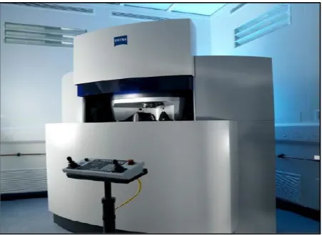
[image:27.595.73.525.369.699.2]There are also several Micro-CMMs that have been commercialized. One of them is Carl Zeiss F25 micro-CMM as in Figure 2.2 [16]. The Carl Zeiss F25 was initially developed by the Technical University of Eindhoven (TUE) [17], and commercialized by Carl Zeiss. The unique design of its kinematic system allows the F25 to eliminate some geometric errors and thus increase the stiffness and accuracies of the machine [1]. The claimed measurement capability is (100 x 100 x 100) mm with resolution of 7.5 nm and measurement uncertainty of 250 nm. The F25 uses a probing system with silicon membrane chip with piezoresistive sensor for its detection mechanism and a stylus tip of 100 µm to 700 µm in diameter. The probing force recorded in this micro probe was less than 0.5 mN μm-1 [16].
29
2.4.
Probing system for micro-CMMs
The stylus shaft and stylus tip are major components influencing micro-probes for micro-CMMs. As defined in ISO 10360-1 [18] for conventional CMM, the probe is defined as the complete devices that generates a signal during probing while the stylus is the mechanical devices that consist of a stylus shaft and a stylus tip. The stylus also establishes the physical contact with the workpieces, coupling its positional information to the probe sensor. Figure 2.3 illustrates the components of probing system.
[image:28.595.173.506.469.729.2]Over the last decade, research and development of micro-probes for Micro-CMM have focused on the sensor mechanism of the probes rather than the stylus system. It can be understood that the detection mechanism in the micro-probes makes a major contribution to probing error and the source of uncertainty in measurements. Thus, it is essential to find the best approaches for detection mechanisms in different probe systems. These include, for instance, using mechanical techniques, capacitive sensors, optical techniques and vibration detection technique. However, in recent years, the increasing numbers of complex miniature products have driven research in micro probes to focus increasingly on shrinking the dimension of the stylus system itself. To provide context, the following section will review several probing systems of micro CMM which have been developed previously.
Figure 2. 3: Probing system according to ISO 10360-1 [18]
1) Ram
2) Probe extension 3) Probe changing system 4) Probe
30 2.4.1. Conventional tactile Styli for Micro CMM probing system
The stylus systems categorised in this group are those for micro CMMs that have a similar design to those for the conventional CMM probing systems. As described in the ISO 10360-1 [18], the stylus systems mentioned have a spherical stylus tip, a rigid, straight and cylindrical stylus shaft, and (means of coupling to) a sensing element. These styluses operate in contact mode.
2.4.1.1. UMAP Mitutoyo probing system
The Mitutoyo UMAP stylus system was first developed by a group of researchers in 1993 to 1999 at the University of Tokyo, Japan [19]. After that, this research has been continued by the Mitutoyo Research Centre Europe and commercialised by the Mitutoyo Company [20]. There are three models of the stylus system, which are UMAP 103, UMAP 110
[image:29.595.99.498.482.737.2]and UMAP 130. UMAP 103 consists of the smallest diameter of a sphere stylus tip, which is 30 µm, with a stylus shaft of 20 µm in diameter and 3 mm in length. The UMAP 110 consists of a stylus sphere tip diameter of 100 µm, with a stylus shaft diameter of 80 µm and a stylus length of 10 mm. The UMAP 130 consists of a stylus sphere tip of 300 µm, a stylus shaft diameter of 200 µm and a stylus length of 10 mm. Figure 2.4 shows the construction and components of the stylus system [20].
31 This stylus system was initially developed for the profile measurement of ink jet and fuel injection nozzles. For this intention, it was designed to have a long and thin stylus which can access a micro-hole to some depth. Thus, one of the advantages of this stylus is it can perform high aspect ratio measurements [21]. Most of the literature that described this stylus system focused on the sensor mechanism when in contact with the workpieces. The UMAP stylus uses a piezoelectric force sensor as the driving and sensing electrode. The stylus is vibrated in its axial resonant state at approximately 350 kHz by the driving electrode. Meanwhile, the sensing electrode will detect any changes in the stylus’ vibration amplitude,
phase or resonant frequency [2] [21].
In terms of the fabrication process of the stylus system, the stylus shaft is made of nickel-chromium (Ni-Cr) and the stylus tip sphere is made of glass. By using the glass to metal sealing technology, melted glass is mounted like a water drop at the tip of Ni-Cr wire stylus shaft. The surface tension of the glass will form the sphere shape. The assembly process occurs in a vacuum chamber. One of the reasons that a Ni-Cr stylus shaft was selected in this design is because of its affinity towards the glass is extremely high[21][2]. Other important feature of the UMAP stylus system is the ability to mount to the Mitutoyo micro-CMM. The repeatability of the UMAP 103 is less than 0.1 µm. The measuring range of the UMAP 103 is (245 x 200 x 200) mm, with a contact force of 0.15 µN to 10 µN and stiffness of 21 kN/m. The UMAP 103 stylus system can also be removed, installed, and replaced easily by the user.
2.4.1.2. NPL capacitive SCMM probe
32 This design provides equal stiffness of the suspension for all horizontal probing directions. It also has a light structure with a low probing force. The probing force is approximately 0.1 mN with a probing deflection of 10 µm, and the weight of the probe is 350 mg. Other characteristics of this design are, the stylus shaft is made of tungsten carbide, the stylus tip sphere is made of silicon nitride and the diameter of stylus tip is 1mm. The positional uncertainty of this design is between 50 nm and 100 nm [12].
[image:31.595.101.496.346.692.2]The main contribution of this NPL stylus system is the generation at that time of knowledge about how to achieve equal stiffness in each axis and the low probing force. However, it is considered as the first generation of stylus system for micro-CMM, where the 1 mm in diameter for the stylus tip is no longer relevant to current needs. Nevertheless, the information on the material and design used in the stylus tip and shaft can be a reference to this study.
33 2.4.1.3. TUE/ XPRESS Gannen Stylus
This probe stylus system was first developed by the Eindhoven University of Technology, TUE [22]. The TUE probe has later been commercialised by a company named Xpress Precision Engineering in the Netherlands [23] [24] . Figure 2.6 illustrate this probing system. The TUE probe was successfully developed with a nanometre capability in uncertainty, and with a low probing force around the range of mili-newtons. This probe consists of a silicon membrane, three slender rods with triangular orientation, and stylus system. The stylus system comprises of stylus tip with a diameter ranging from 50 µm to 500 µm. This orientation is designed in order to achieve the thermal and mechanical stability. On the centre is a moving platform of this chip where a stylus is attached at the end of the probe tip. An elastic deformation of the three slender rods is expected to be occurred during displacement of the probe tip and it is measured by piezo resistive strain gauges [23].
Figure 2. 6: Image of the first prototype of TUE probe (left) [22] , and it had been improved and commercialised by Xpress Precision engineering (right) [23]
Other important feature of this stylus is that it has low moving mass, which is 25 mg including the stylus shaft and tip. The stiffness of the probe is 480 Nm-1 with a hysteresis of 0.05 % and the standard deviation of repeatability is recorded at 2 nm, while the 3D uncertainty is 10 nm. This stylus also gives equal measurement sensitivity in every axis [23].
2.4.1.4. METAS probing system
34 three inductive sensors that are mounted on the probe housing. During single point probing, the probe deflection is recorded at different positions to obtain a force-distance curve for the measurement point. The flexures hinges are made from aluminium by using the milling and EDM processes. One of the unique features in this system is all the axes are inclined by 45 degrees and thus, will have equivalent orientation with respect to gravity when the probe is mounted on a CMM. A permanent magnet is also located in the system to eliminate the sagging phenomena due to gravity [21][2].
Figure 2. 7: image of component and construction of METAS Probing and stylus System [23] The diameter used for this stylus tip sphere is 100 µm to 300 µm while probing force is below 0.5 mN, and the stiffness of the probe was recorded at 20 Nm-1. The moving mass is 7 g, which is quite high and as a result, a plastic deformation may occur either on the surface of the measured workpiece or stylus tip itself. An elastic element is used to reduce the influence of colliding mass [2] [21]. A completed series of performance tests on this stylus system, especially covering repeatability and isotropy have also been conducted [25]. The probing acceptance method based on ISO 10360-2 [27]was also conducted. From these tests, the repeatability is 5 nm and the roundness deviation is 40 nm for the sphere with a 300 µm diameter tip [25].
35 2.4.1.5. Piezoresistive based stylus
A piezoresistive based stylus for the micro-CMM is another new stylus system developed by a group of researchers in PTB Germany [28][29], as shown in Figure 2.8. Similar to other types of stylus systems that have been discussed previously, the focus of this research is mainly on the sensing mechanism part of the probing system, as this probe uses a silicon membrane with diffused piezoresistor as the sensing element.
Figure 2. 8: Piezoresistive stylus system [28]
This stylus consists of a silicon membrane with the piezoresistor layer at the back side of the membrane, which is used as the sensing element, a 7 mm effective length of stylus and a 300 µm in diameter of the stylus tip sphere. The silicon membrane is fabricated using the KOH-etching technique while the piezoresistor layer is fabricated using standard micro fabrication technique for insulation, diffusion and metallization. The stylus shaft is glued at the centre boss of the membrane. Figure 2.8 shows the components of this stylus.
In theory, as shown in Figure 2.9 the silicon membrane will sense any deformation and mechanical stress caused by any deflection of the stylus tip when it is in contact with the surface. The piezoresistors will transform the deformation and mechanical stress into electrical output signal through changing their electrical resistance, where the change of electrical resistance is proportional to the mechanical stress.
36 A few designs have been investigated at PTB to improve the sensitivity of the probe and the stiffness of the suspension. From the finite element analysis, adding aperture design to the membrane will increase the sensitivity of the probe [28]. A double triangle design of the silicon membrane was proposed to improve the stiffness of the suspension. With this new design, the results showed that the original anisotropic stiffness could be improved to a nearly isotropic stiffness of suspension.
In contrast, there is no further information on the reaction of this stylus towards the surface interaction force during measurements. The physical characteristic of the stylus, such as the roughness error of the stylus tip sphere and the diameter of the stylus shaft were also not mentioned in this research. Moreover, the investigation of performance for this stylus system should be continued with a smaller stylus tip sphere diameter of less than 300 µm because the probe qualification test, which was conducted in this research may not be suitable when testing the smaller sphere tip diameter.
Figure 2. 9 : working principle of stylus deformation [28] 2.4.1.6. Fizeau Interferometer based Stylus
37 interferometer. The probing force and probing stiffness behaviour of this stylus system, theoretically and experimentally, are also investigated and reported by the authors [30].
[image:36.595.185.428.310.531.2]This Fizeau interferometer stylus was successfully demonstrated for probing in millinewton range. The drawbacks of this stylus include an ability to operate in 1D measurement only, and the stiffness not being similar in all axes. However, no further information was mentioned about the probing force characteristics, bending behaviour and physical information of the stylus shaft and stylus tip sphere, including the diameter of the stylus shaft and stylus sphere, materials used, roughness and roundness of the sphere. The focus of the paper is more on the behaviour and characteristic of the sensing element and the mechanism of this stylus system.
Figure 2. 10: Fizeu interferometer stylus system [30] 2.4.1.7. NPL Vibrating Stylus
38 measurement surface and its acceleration is sufficient when contacting the measurement surface. The frequency of oscillation is about 1.6 kHz and vibration amplitude is 1 µm [31]. Any interaction between the stylus tip and measurement surface will cause the change in amplitude and will be captured by the two piezoelectric sensors at either end of the flexures. The probe stiffness determined from the modelling is estimated around 15 Nm-1.
[image:37.595.133.469.364.666.2]A broad simulation and characterisation of this stylus has been reported [33], including the understanding of the load parameter, the surface force characteristic, the snap in and snap out phenomena, and the sensitivity of the stylus in vertical and lateral direction. However, these characterizations seemed to focus more on the functionality of the sensing element in the probing system itself rather than the characterisation of the stylus system, including the quality of the stylus, the form and roughness error of stylus sphere tip, and the probe tip calibration, which were not addressed in details.
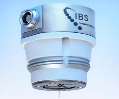
39 2.4.1.8. IBS Triskelion Ultra-Precision Touch Probe.
[image:38.595.201.395.306.466.2]As shown in Figure 2.12, this probe uses a stylus shaft made from tungsten carbide and ruby for the stylus tip. The diameter of the stylus tip recorded in the literature is between 70 µm to 500 µm, while the diameter of the stylus shaft is 50 µm. The flexure used in this system was made from monolithic metal foil and it is elastically suspended, thus, allowing deflection of the tip during probing measurement. The displacement of these targets is measured with the capacitive sensors and can be used to determine the X, Y, and Z deflection of the probe [35]. Other features of this stylus system are the stiffness are: 70 Nm-1 isotropic in every axis, the suspended mass of 160 mg, measurement range of 10 µm, and 3D measurement error recorded is less than 15 nm [36][37].
Figure 2. 12: IBS Triskelion Ultra-Precision Touch Probe 2.4.1.9. Differential Capacitor Based Stylus
40 As shown Figure 2.13, the micro capacitive sensors consist of a floating plate and a fixed plate. Four pillars are used to separate them, hence, making a nominally uniform gap between the floating and fixed plate. The fixed plate itself has been separated into four equal parts that are connected electrically by wires. The sensing principle can be summarised as follows; when the stylus tip sphere contacts the measured surface, the probing force will be exerted by the system. This probing force will cause translational motion in the Z direction and tilt motion about the X and Y axes of the floating plate. The four sections of the fixed plate will experience differently varying capacitances with the floating plate caused by its translational and tilt motion. These capacitance differences are sent to a computer via signal processing circuit for analysis to determine the tip motion.
Figure 2. 13: Differential capacitor based stylus system
41 2.4.1.10. Tri-Switch Stylus
The tri-switch stylus system has been developed by a research group from the National Taipei University of Technology, in 2013 [39][40]. As compared to the other stylus systems that have been discussed in this chapter, this research does not only focus on the sensing element, but also the information on the stylus shaft and tip. As shown in Figure 2.14, the diameter of the stylus tip sphere used is 80 µm and is made of glass, while the diameter of the stylus shaft is expected to be smaller than the diameter of the stylus tip sphere. The stylus shaft is made of wire electro-discharge grinding (WEDG) process and adhesive hybrid technology was used to assemble the stylus tip sphere onto the stylus shaft. For the sensing element, this stylus uses the concept of triggering mechanical system. The metal plate with three micro wire rods was placed on the supporting base. The sensing wire rods were fixed onto the micro wire. The stylus shaft will then be assembled in the centre of the metal plate. The sensing wire rod will function as the on-off switch. When force is applied to the stylus tip, the metal plate will oscillate and thus, causing the contact point between the sensing wire and micro wire like the on-off switch. At the same time, the signal from the on-off switch will be triggered by the electronic systems. Additionally, the sensitivity of this probe is only in the micrometre range and need to be improved for micro-CMMs application.
42 2.4.1.11. Variable Stiffness Probing System
A completely new concept of probing systems with tuneable stiffness and a description of the operating procedure is presented in this paper [41] [42]. The design of the sensor mechanism for a variable stiffness probing system was based on a novel suspension structure that allows compressive force to be applied to the main spring elements within the structure. The spring element is made of a long slender beam for the wide range of geometrical measurement can be performed. The loads can be applied using a piezo-electric or other similar form of actuator at the end of each beam. This design structure allows a
probing system to operate in either “stiff” or “flexible” mode at which can be selected at a
certain position. A stiff mode is selected when approaching the measured workpiece, while at the certain predetermined location where the distance between the stylus tip and measured workpiece is small, the stylus is operated in the flexible mode when the stiffness at a minimum to ensure a low contact force occurred. Then, after measurement contact is performed, the stylus is switched back to the stiff mode [42].
Figure 2. 15: Schematic diagram for variable stiffness probe [42]
43 allow an accurate position relative to the suspension structure. The vertical positions of the sensors are varied within the probe fixture to allow an optimum working gap at an approximately 100 µm. In order to allow stiffness modulation of the suspension structure, three piezoelectric actuators with 8 µm maximum displacement are mounted to the probe fixture. A set of three sliding clamps are employed to ensure that the actuators are positioned in intimate contact with the load application points on the suspension structure. [43]. The probe stiffness is varies from 914 Nm-1 to 2853 Nm-1 in vertical direction while from 410 Nm-1 to 610 Nm-1 in lateral direction [43]. The first promising experiment conducted resulted in an uncertainty of the probing system in about 60 nm which shows that the issue of drift and stylus tip displacement while switching the stiffness need to be resolved [4].
2.4.2. Non-conventional tactile styli design of probing system for micro-CMM
There are two criteria for stylus systems to be categorised here as ‘non-conventional’. The first criterion is the styluses have a unique design, which is not following the normal design of the stylus system of micro CMM described generally by ISO 10360-1 [18] (as illustrate in Figure 2.3 in section 2.4). For the normal design of the stylus system as discussed before, the stylus with a rigid, straight, and cylindrical stylus shaft, a spherical stylus tip is attached at the end of stylus shaft and an interface between the stylus and the sensing element. The second criterion is that, while having important characteristics in common with a tactile stylus system, it actually functions as a non-contact stylus when measuring the surface. Thus, the stylus systems discussed in this section either do not have a stylus shaft, or a stylus tip sphere or are operated in a non-contact mode when measuring the surface.
2.4.2.1. PTB-Werth Fibre Stylus
44 This stylus system uses optical imaging in the detecting mechanism. In detail, as the stylus tip comes into contact with the workpiece, the stylus tip will be deflected, and this deflection is detected by a camera system of the optical Micro CMM where the position of the probing point is calculated by high accuracy image processing [21][44]. The measurement can be done either by the use of backlight illumination, which measures the resulting shadow of the ball tip or detects the position of a self-illumination probing (hence the use of an optical fibre). The stylus tip sphere in this stylus system was initially used for both tactile probing and optical measurements by the camera system. Thus, problems could occur when the optical light path was disturbed by, for instance, effects resulting from the penetration depth in a small, deep hole. Such effects would consequently lead to measurement error. Nevertheless, this problem has been solved by adding a second sphere that is located on the fibre shaft, above the stylus tip sphere. This second sphere is used for optical detection of the fibre deflection, but does not penetrate the measured structure, as shown in Figure 2.17 [21].
Figure 2. 16: Opto-Tactile PTB-Werth Fibre Probe [45]
![Figure 2. 3: Probing system according to ISO 10360-1 [18]](https://thumb-us.123doks.com/thumbv2/123dok_us/9457041.452640/28.595.173.506.469.729/figure-probing-system-according-to-iso.webp)
![Figure 2. 4: Construction of UMAP stylus system [20]](https://thumb-us.123doks.com/thumbv2/123dok_us/9457041.452640/29.595.99.498.482.737/figure-construction-umap-stylus.webp)
![Figure 2. 5: NPL Capacitive Stylus [12]](https://thumb-us.123doks.com/thumbv2/123dok_us/9457041.452640/31.595.101.496.346.692/figure-npl-capacitive-stylus.webp)
![Figure 2. 7: image of component and construction of METAS Probing and stylus System [23]](https://thumb-us.123doks.com/thumbv2/123dok_us/9457041.452640/33.595.178.418.232.496/figure-image-component-construction-metas-probing-stylus.webp)
![Figure 2. 10: Fizeu interferometer stylus system [30]](https://thumb-us.123doks.com/thumbv2/123dok_us/9457041.452640/36.595.185.428.310.531/figure-fizeu-interferometer-stylus-system.webp)
![Figure 2. 11: NPL vibrating stylus [31]](https://thumb-us.123doks.com/thumbv2/123dok_us/9457041.452640/37.595.133.469.364.666/figure-npl-vibrating-stylus.webp)
![Figure 2. 22: Principle of spherical capacitive plate [38]](https://thumb-us.123doks.com/thumbv2/123dok_us/9457041.452640/47.595.88.507.470.721/figure-principle-of-spherical-capacitive-plate.webp)