© 2019, IRJET | Impact Factor value: 7.211 | ISO 9001:2008 Certified Journal
| Page 1611
Orthogonal Frequency Division Multiplexing (OFDM) based Uplink
Multiple Access Method over AWGN and Fading Channels
Prashanth G S
11
Department of ECE, JNNCE, Shivamogga
---***---Abstract -
Orthogonal Frequency Division Multiplexing
(OFDM) is a method of encoding the input data over
multiple narrowband carriers. In this paper, QPSK
modulation technique is used for OFDM. Delay spread in
wireless communication introduces Intersymbol
interference(ISI). OFDM mitigates the effect of ISI. When
conventional OFDM is used for uplink, the problem with
OFDM is peak-to-average power ratio(PAPR). PAPR
reduces the power efficiency of the system. To mitigate
the effects of PAPR, Super-Orthogonal Convolutional
codes along with golay codes are used in OFDM. With
reduced PAPR, OFDM signal is transmitted over Wireless
communication channel. Wireless communication
channel introduces fading under various conditions. In
this Paper, OFDM signal is analyzed over AWGN,
Rayleigh and Rician fading channels. In AWGN channel,
the increase in Signal to Noise Ratio(SNR) reduces bit
error rate(BER). In case of fading channels, the amount
of fading in multipath component is an important
parameter which decides BER. The effect of fading on
OFDM signal is observed by simulation using MATLAB
R2010a. The fading channel which suits OFDM is
proposed.
Key Words: OFDM, AWGN, FADING, QPSK, BER, SNR, PAPR, SOCC, Golay codes
1. INTRODUCTION
OFDM is a signal modulation technique in digital domain. Input data stream in OFDM is split across several separate narrowband channels at different frequencies to minimize interference and crosstalk. OFDM Transmits the original input data bits parallel as compared to serial data transmission in conventional modulation techniques. OFDM is a special case of Frequency division multiplexing (FDM) scheme in which numerous closely spaced carriers are used for data transmission. The carriers used in OFDM are Orthogonal to each other.FDM needs separate filter for each sub-channel, OFDM does not require it. The sub-carrier spacing for orthogonality requires δf=k/Tu, where Tu is the symbol duration and ‘k’ is positive integer. Typically ‘k’ value is chosen as one .With ‘N’ sub-carriers, the total bandwidth will B=Nδf. OFDM introduces a concept of guard interval which gives better Orthogonality. The orthoganility allows for
efficient modulator and demodulator implementation using the FFT algorithm on the receiver side and inverse FFT on the sender side. Each sub-carrier is modulated with a conventional modulation scheme at a low-symbol rate. Convolution encoding and interleaving are the two techniques used in OFDM to reduce errors.
In OFDM, the user close to base station will be assigned a large number of channels. These users use higher modulation schemes to give high throughput. If the user moves away from the base station the number of channels to be used will be reduced . The modulation scheme will change from higher modulation technique to lower modulation technique. So, capacity also decreases. The main advantage of OFDM is its ability to cope with severe channel conditions such as, attenuation of High frequencies and narrowband interference. OFDM also copes up with multipath fading without the use of complex equalization filters. Because of low symbol rate between the guard interval, ISI is eliminated.
Bit error rate performance in OFDM increases as the signal passes through different propagation channels. Some of the fading channels such as Rician and Rayleigh fading channels along with AWGN are used as propagation channels for OFDM. Fading deals with signal attenuation. Fading happens due to signal going through different paths called multipath fading and also due to obstacles which attenuates signal. In AWGN, the probability distribution of noise samples is Gaussian and it has uniform distribution of power across the whole frequency band[4]. Bit error rate of OFDM with AWGN noise is always less compared to fading channels. Practically, OFDM signal passes through different fading channels other than AWGN. The performance of OFDM varies with different fading channels. In this work, OFDM signal is analyzed with fading channels. The fading channel which gives less BER is proposed for OFDM. Next few sections will give a deep insight on OFDM, AWGN and fading channels.
2.
Orthogonal
Frequency
Division
Multiplexing(OFDM)
© 2019, IRJET | Impact Factor value: 7.211 | ISO 9001:2008 Certified Journal
| Page 1612
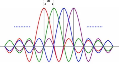
Sub-carriers used in OFDM are orthogonal to each other. [image:2.595.311.540.36.409.2] [image:2.595.49.285.145.272.2]Frequency domain representation of sub-carriers is shown in Figure 1.
Figure 1: Frequency domain representation of orthogonal subcarriers used in OFDM
Δf is the difference in the frequency between the two carriers. Δf is chosen such that, when the amplitude of the carrier is maximum, then the other sub-carriers tends to zero at that point. In case of cellular communication, the uplink is base station. Delay spread in wireless communication introduces Inter Symbol Interference(ISI). OFDM mitigates the effect of ISI using cyclic prefix . The cyclic prefix used in OFDM to primarily act as a guard band between successive symbols to overcome intersymbol interference(ISI). Use of cyclic prefix is a key element of enabling the OFDM signal to operate reliably. OFDM transmits symbols to base station in blocks with guard interval inserted between the blocks of OFDM. Addition of cyclic prefix in OFDM is shown in Figure 2
Figure 2: Cyclic Prefix insertion between the OFDM symbols to mitigate ISI
3. QUADRATURE PHASE SHIFT KEYING(QPSK)
QPSK is a type of phase modulation technique. QPSK is used to modulate 2 bits per symbol with four possible phase shifts with a phase difference of 900. So, with the same bandwidth
the data rate is doubled compared to BPSK. So, Bandwidth efficiency is improved[4]. QPSK modulated wave can be represented by
2
( )
cos
2
1
4
i c
E
S t
i
w t
T
---(1)Where ‘T’ is Symbol Duration
The average bit error rate, BER for QPSK is given by
BER= ---(2)
The probability of symbol error is given by
2
0 eE
P
erfc
N
--- (3)For QPSK, E= 2Eb --- (4)
E= Symbol energy, Eb=bit energy &
N0= Noise Spectral density
0 b e
E
P
erfc
N
- - - (5)4. ADDITIVE WHITE GAUSSIAN NOISE (AWGN)
Additive white Gaussian noise (AWGN) is additive because it will add to any noise already present and is white because it has uniform power over frequencies. It follows normal distribution. It is a basic and generally accepted model for thermal noise in communication channels. It is used in Information theory to imitate the effect of many random processes that occur in nature[3]. With AWGN channel , the capacity is given by
1
log(1
)
2
P
C
N
--- (6)
where N is noise level and P is maximum channel power. The
probability distribution of the normal distribution is: 2 2 ( ) 2 2
1
( )
2
xf x
e
--- (7)
where ‘µ’ is mean, ‘
’ is standard deviation and
2is the variance.5. FADING CHANNELS
5.1. Rayleigh Fading Channel:
© 2019, IRJET | Impact Factor value: 7.211 | ISO 9001:2008 Certified Journal
| Page 1613
radio signals, such as that used by wireless devices. InRayleigh fading channels, the magnitude of the signal will fade according to Rayleigh distribution. Rayleigh fading is applicable when there is no dominant propagation along the line of sight between the transmitter and the receiver [3][5].
With sinusoidal carrier in the transmitter, the propagation channel can be modeled as
x t
( )
sin
ct
--- (8)The signal received over Rayleigh fading channel with multiple components is given by
1
( )
sin(
)
N
n c n
n
y t
t
--- (9)
‘
n’ is the amplitude of the nth reflected wave. ‘
n’ is thephase of nth reflected wave. ‘n’ varies between 1 to some
positive value which gives the number of scattered components. No direct path signal component is present in Rayleigh fading channel. When the signal passes through Rayleigh fading channel, the magnitude of the signal varies based on Rayleigh distribution. Rayleigh distribution is a continuous probability distribution. The probability density function of the Rayleigh distribution is given by
2 2
2
( )
x
(
x/ 2
)
f x
e
--- (10)
Where ‘
’ is the scaling factor. Larger the value of ‘
’, larger will be the spread of the distribution. The cumulative distribution function is
2
2
( ) 1 (
x/ 2
)
F x
e
--- (11)This fading channel scatters the signal in different direction and there is no path component under line of sight (LOS) .
5.2 Rician Fading Channel:
Rician fading or Ricean fading is a stochastic model for radio propagation. The signal arrives at the receiver by several different paths which cause multipath interference. Rician fading is applicable when there is a dominant propagation along the line of sight. In Rician fading, typically line of sight signal is much stronger than the signal coming from different paths [6][7]. With sinusoidal carrier in the transmitter, the propagation channel can be modeled as
( )
sin
cx t
t
--- (12)
The signal received over Rician fading channel with multiple components is given by
1
( )
sin
sin(
)
N
c n c n
n
y t
A
t
t
--- (13)
Where ‘A’ is the amplitude of the line of sight component.
‘
n’ is the amplitude of the nth reflected wave. ‘
n’ is thephase of nth reflected wave. ‘n’ varies between 1 to some positive value which gives the number of scattered components. The probability distribution function (pdf) of the received signal amplitude is given by
2
2( 1) ( 1) ( 1)
( ) K xexp K x o 2 K K
f x K I x
--- (14)
Where K= power in direct path to the power in other scattered paths. ‘Ω’ is the total power from the paths and is a scaling factor. I0 is the Bessel function of order 0.
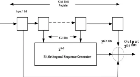
[image:3.595.314.572.322.478.2]6. BLOCK DIAGRAM
Figure 3: Block Diagram of OFDM Transmitter &
Receiver
The super-orthogonal convolutional codes (SOCC) are a class of low-error correcting codes [1]. SOCC consists of K-1 shift registers. It outputs an orthogonal sequence of length 2K-2 as
shown in the Figure 4.
[image:3.595.314.559.597.733.2]© 2019, IRJET | Impact Factor value: 7.211 | ISO 9001:2008 Certified Journal
| Page 1614
The coding rate of SOCC Encoder, Rc= 1/2K-2 . GolayComplementary sequences reduces PAPR by 3 db. Golay Orthogonal sequence can be obtained using this generator. Golay Orthogonal Sequences can be obtained by
2
G G
N N
G
N G G
N N
H
H
H
H
H
---(15) [2]2
G
H
---(16) [2]
Where the matrix HN-G denotes the variant of HNG which
corresponds to the right half columns negated[1]. Next the orthogonal sequences are modulated using QPSK modulation. Detailed explanation of QPSK is already given in section 3. Two bits will treated as one symbol in QPSK. Each two bits are mapped to one sub-carrier. All the sub-carriers are Orthogonal to each other. Then IFFT is performed on the mapped sequence to an OFDM signal. Cyclic Prefix is added between OFDM symbols to mitigate the effect of ISI. Time domain sample of OFDM is given by
/ 2 1 2 / / 2
( )
[ ]
N
j kt N k N
x t
X k e
---(17)Where X[k] is the frequency domain sample of OFDM signal.
At the receiver side, the Cyclic prefix is removed initially and two FFTs are used at the receiver. One FFT is used for equalization, and another FFT is used convert OFDM signal from the time domain to the frequency domain. The Frequency domain sample of OFDM signal is given by
/ 2 1
2 /
/ 2
[ ] 1/
( )
N
j kt N
t N
X k
N
x t e
---(18)
Where x(t) is the time domain sample of the OFDM symbol. The Viterbi decoding is used at the receiver to get back original data bits.
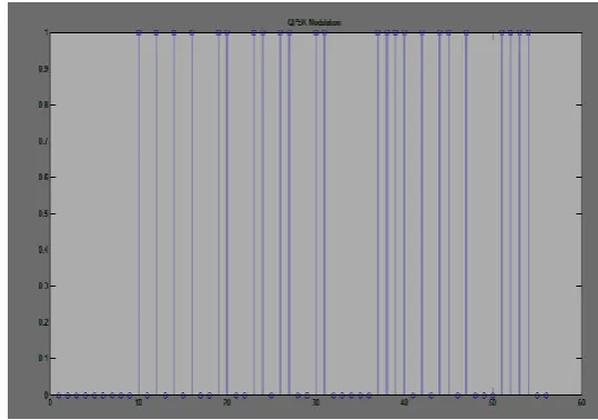
[image:4.595.305.575.121.310.2]7. SIMULATION RESULTS
[image:4.595.72.275.156.243.2]Figure 5: Discrete QPSK Modulation for (56 bits)
seven 8-bit Orthogonal sequences
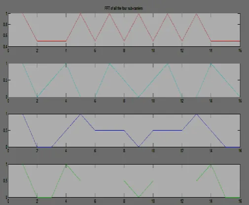
Figure 6: Four different Subcarriers (Subcarrier
Mapping)
[image:4.595.308.571.357.514.2]© 2019, IRJET | Impact Factor value: 7.211 | ISO 9001:2008 Certified Journal
| Page 1615
[image:5.595.39.569.107.791.2]Figure 8: Cyclic Prefix added to IFFT of all
subcarriers
Figure 9: OFDM Signal
Figure 10: OFDM signal with AWGN Channel
[image:5.595.310.573.330.502.2]Figure 11: OFDM signal over Rayleigh fading
channel
Figure 12: OFDM signal over Rician fading
channel
[image:5.595.38.289.333.530.2]© 2019, IRJET | Impact Factor value: 7.211 | ISO 9001:2008 Certified Journal
| Page 1616
Figure 14: FFT of subcarriers for received data
from Rayleigh fading channel
Figure 15: Recovered data from Rayleigh fading
channel(Blue lines indicates the transmitted data
& red lines indicates the received data)
Figure 16: Cyclic prefix removed from OFDM
signal in Rician fading channel
Figure 17: FFT of subcarriers for received data
from Rician fading channel
Figure 18: Recovered data from Rician fading
channel(Blue lines indicates the transmitted data
[image:6.595.75.563.323.500.2]& red lines indicates the received data)
[image:6.595.38.567.566.738.2]© 2019, IRJET | Impact Factor value: 7.211 | ISO 9001:2008 Certified Journal
| Page 1617
Figure 20: FFT of subcarriers for received data
from AWGN channel
Figure 21: Recovered data from AWGN Channel
Total of 56 bits are used as input digital bits. Each 8 bit represents one Orthogonal Sequence. So, for 56 bits, total of 7 orthogonal sequences are used. Orthogonal sequences used in the work are as follows: 00000000; 01010101; 00110011; 01100110; 00001111; 01011010; 00111100;
8. CONCLUSIONS
In this paper, PAPR reduction in OFDM signal is done using Super Orthogonal Convoltional codes and Golay codes. OFDM signal with less PAPR is transmitted over AWGN, Rayleigh and Rician fading channels. The effects of these channels on OFDM signal is studied using simulation. From the results it is observed that, OFDM performs well in AWGN channel compared to Rayleigh and Rician fading channels. With the increase in the Signal to noise ratio (SNR) in AWGN channel, the bit error rate(BER) is reduced. In cellular communication, the use of OFDM in Uplink always
encounters fading channels. From the results, it is found that Rician fading channel outperforms Rayleigh fading channel for OFDM based uplink multiple access method.
REFERENCES
[1] Hideki Ochiai, Yu Takayama, “ A Simple OFDM-Based Multiple Access System with Super-Orthogonal Convolutional Codes and Golay Sequence”, Wireless Communications and Networking Conference, 2009. WCNC 2009 DOI: 10.1109/WCNC.2009.4917547, May 2009
[2] Yuta Hori, Hideki Ochiai, “A New Uplink Multiple Access Based on OFDM With Low PAPR, Low Latency, and High Reliability , IEEE Transactions on Communications, Vol. 66, No. 5, May 2018
[3]Prashanth G S, “Analysis of FHSS-CDMA with QAM-64 over AWGN and Fading Channels”, International Research Journal of Engineering and Technology (IRJET) , e-ISSN: 2395-0056 , p-ISSN: 2395-0072, Volume. 04,Issue. 08, pp. 2100-2103, August 2017.
[4] Prashanth G S, “Comparative Analysis of Various Digital Modulation Techniques for FHSS-WCDMA over AWGN and Fading Channels” , International Research Journal of Engineering and Technology (IRJET), e-ISSN: 2395-0056 , p-ISSN: 2395-0072, Volume. 6 ,Issue. 02, pp. 908-913, February 2019.
[5] Rashmi V, Darshini S M, Rashmi H G, Prashanth G S, “Simulation of FH-CDMA for AWGN and Fading Channels”, IFRSA International Journal Of Electronics Circuits And Systems, DOI: 10.13140/RG.2.2.19606.19527 Vol 4, issue 2, pp. 95-98,July, 2015.
[6]Gary.J.Mullett, “Introduction to Wireless Telecommunications Systems and Networks”, ISBN-10:81-315-0559-6, year 2011.
[7] Rashmi V, Darshini S M, Rashmi H G, Prashanth G S, “Simulation of FH-CDMA for AWGN and Fading Channels”, IFRSA International Journal Of Electronics Circuits And Systems, Vol 4, issue 2, pp. 95-98,July, 2015.