http://dx.doi.org/10.4236/jbise.2012.53016 Published Online March 2012 (http://www.SciRP.org/journal/jbise/)
FPGA implementation of fractal patterns classifier for
multiple cardiac arrhythmias detection
Chia-Hung Lin, Guo-Wei Lin
Department of Electrical Engineering, Kao-Yuan University, Kaohsiung City, Taiwan Email: [email protected]
Received 2 December 2011; revised 30 December 2011; accepted 29 January 2012
ABSTRACT
This paper proposes the fractal patterns classifier for multiple cardiac arrhythmias on field-programmable gate array (FPGA) device. Fractal dimension transfor- mation (FDT) is employed to adjoin the fractal fea- tures of QRS-complex, including the supraventricular ectopic beat, bundle branch ectopic beat, and ventricu- lar ectopic beat. FDT with fractal dimension (FD) is addressed for constructing various symptomatic pat- terns, which can produce family functions and enhance features, making clear differences between normal and unhealthy subjects. The probabilistic neural network (PNN) is proposed for recognizing multiple cardiac arrhythmias. Numerical experiments verify the effi- ciency and higher accuracy with the software simula- tion in order to formulate the mathematical model logical circuits. FDT results in data self-similarity for the same arrhythmia category, the number of dataset requirement and PNN architecture can be reduced. Its simplified model can be easily embedded in the FPGA chip. The prototype classifier is tested using the MIT-BIH arrhythmia database, and the tests reveal its practicality for monitoring ECG signals.
Keywords: Field-Programmable Gate Array (FPGA); Fractal Dimension Transformation (FDT); Fractal Dimension (FD); Probabilistic Neural Network (PNN)
1. INTRODUCTION
The electrocardiogram (ECG) signal can be measured non-invasively by placing electrodes on the body surface that provides information of myocardium electric activity and heart physiological function. An ECG signal shows as an almost periodic signal, and can reveal symptomatic information in the dysfunction duration. Currently, port- able and stationary monitoring devices have been used on healthcare systems. Holter recorder is a well-known portable device and used to record the electrical activity with surface electrodes placed on the chest. However, its diagnostics is off-line analysis from the recorded data,
and uses a cardiogram to identify arrhythmic types of the patients. Stationary monitors, such as dedicated or PC- based devices, have also been used on healthcare systems, which results in expensive solutions and limiting the port- ability [1,2]. Since telemedicine has also been used to acquire patient’s information, and has portable configu- ration for patient monitoring in remote non-clinical en- vironments, it can be used in home healthcare, elder com- munities, and public place to acquire patient’s information. It has become a commonly used technology due to its low-cost, compactness, and short design-cycle. This re- mote device is an embedded hardware with FPGA, Blue- tooth, RFID, and Zigbee. Via wireless transmission be-tween the biosensor and supervision device, FPGA makes the ECG signal processing and sends digital signal to a remote monitor [3]. For a portable monitor design, FPGA device provides a promising solution to hardware implements.
To overcome the drawbacks, an iterated function sys- tem (IFS) is proposed for modeling the non-linear inter-polation function [10-14]. Its modification, the so-called FDT function, is simple in form and consists of sinusoid- dal terms to the affine maps, making the model more flexi- ble for processing irregular signals. FDT functions with FD are used to construct the fractal patterns from ECG signals in the time-domain, including the “Q-R Segment” and “R-S Segment”. The transform method results in data self-similarity and enhances the features for the same cate- gory. The PNN-based classifier is developed to perform the classification tasks. The performance of this method is presented and promising results are given for classifi- cation applications, such as the straightforward mathe- matical operation, flexible pattern mechanism, and high tolerance capability [15-17]. These algorithms can be easily programmed into the FPGA chip. The FPGA de- vice has an inherent parallel architecture allowing de- signers to execute the multiple inputs and control loops simultaneously without slowing down the execution time and applications. From the test results, they appear to be computationally efficient and accurately recognize for patterns classification.
2. MATHEMATICAL BACKGROUND
2.1. Fractal Dimension Transformation (FDT)
An IFS has been proposed for image compression and signal modeling, and is capable of producing family func- tions with different fractal dimensions (FDs). It is a finite set for contraction mappings, and has been used to create images, various waveforms and patterns for medical im- age classification and biomedical signal analysis [10,11]. IFS is implemented with similarity maps, and the result- ing data are self-similar. The significant removal of re- dundancy is related to the self-similarity of natural pat- terns. In modeling the pattern of a function or data se- quence x[t], t = 1, 2, 3, , N, the pth interpolation map Wp, p = 1, 2, 3, , P, can be presented as
p p
pp
p p p
a b e
t t
W
c d f
x t x t
(1)
p p p p
px p p
W t a t b x t e
W x t c t d x t f
p t (2)
For each map, Wp maps the data sequence xp[t] onto
the subsequences with Np sampling data in the interval
[Np1, Np2], and the maps can be constructed side by side. The remaining map parameters cp, dp, and fp can be
solved by minimizing the sum of squared errors between the transformed data and the original data in the range of the pth map, and can be justified by the Collage Theorem [12,13]:
2 1 2 p p Np px p p
t N
e W x t x
(3)where 1
2 1
int p 1
p p
t N n
N N N
, Np = Np2 – Np1 + 1,
and N = N1 + N2 + N3 + ⋯ + Np+ ⋯ + NP. To improve the
constraint, non-linear interpolation is used to adjoin the data among the interpolation points, which makes the model more flexible for processing non-linear and irregular signals. Non-linear terms as sinusoidal functions can be added to Wp. The non-linear interpolation function can be
represented as
sinpx p p p p p p
n
W x t c n d x t f g
N (4)
A fractal pattern of ECG signal can be adjoined with several segments such as P-R interval, P-R segment, Q-R-S complex, S-T segment, or Q-T interval. The non- linear function with fractal dimension (FD) will change the ECG signals into fractal patterns at different scale pa- rameters. FD must be a parameter between 1 and 2 for processing one-dimensional signals. The non-linear in- terpolation function, FDT with FD, can be modified as
sinpt p p p p p p
n x t c n d x t f g
D
(5)
1 1 p D n N
t (6) where D is a FD parameter (1 < D < 2). The remaining map parameters cp, dp, fp, and gpcan be solved by
1 1 p p p N N p Tt t t p
t p t
p
c d
S S S x t
f g
(7)
1 sinT
t p
n S n x t
D
(8)
Apply sequence data xp [t] are the sampling data from
the ECG signals. The fractal patterns can be reconstructed as [14]
1
1, 2,3, ,
P pt pt p
p
p
x t t N
(9)Equations (5) and (6) are used to extract the features from the ECG signals, and Equation (9) is utilized to con- struct the fractal patterns of cardiac arrhythmias.
2.2. Artificial Neural Network (ANN)
has the parallelism distributed process, learning, and pattern recognition ability. In this study, we have considered the sequence data xp[t], t=1, 2, 3, , Np, with P segments
from the ECG signal, and a fractal pattern can be rep- resented as
1 2
11 12 13 1 21 22 23 2
1 2 3
1 , , , , , , , , , , , , P N N P
P P P PN pt p
p
x t
(10)The vector can be also combined as = [11, 12,
13, , 1N1|21, 22, 23, , 2N2|…|P1, P2, P3, ,
PNP] = [1, 2, 3, , i, , N], i = 1, 2, 3, , N, N
= N1 + N2 + N3 + + NP, and each feature i is con-
nected to the input nodes of input layer. The number of input nodes is equal to the number N. The number of hidden nodes Hk (k = 1, 2, 3, , K) is equal to the number of
training data, while the number of summation nodes Sj and
output nodes Oj (j = 1, 2, 3, , m) equals to the types of
cardiac arrhythmias. Therefore, its architecture can be easily to determined without any trial-and-error procedure. The weights IH ki
w (connecting the kth hidden node and the ith input node) and HS
jk (connecting the jth summation
node and the kth hidden node) are determined by K in- put-output training pairs. In the hidden node, a normal- ized Gaussian function Hk is applied to the Euclidean
distance Ed between the unknown pattern and K train-
ing patterns
w
IH ki
w . The function Hk is inversely propor- tional to the distance Ed. If Ed approaches zero, the un-
known pattern is similar to any training data. This concept can be used for analyzing pattern relations. The output Oj can be computed by
22 d 2 1 exp exp 2 IH N i ki k i k w E H 2 2 k
(11)1
1
1, 2,3, ,
K HS jk k k j K k k w H O j H
m (12)where the weights IH ki w
are created by training data (k) = [1(k), 2(k), 3(k), , N(k)], k=1, 2, 3, , k, , K;
the weights wHSjk are the desired outputs associated with
each stored pattern IH ki
w . The value of HS jk
w will be equal to “1” or “0”. The value will be set to be “1” when the kth training data belonged to the jth class; k is the
smooth-ing parameter. Finally, the maximum output Omax= [O1,
O2, O3, , Oj, , Om] indicates the type of cardiac
arrhythmias.
In Equation (11), the smoothing parameter 1 = 2 =
3 = = K= ( 0) would refine the classification
accuracy. The non-linear optimization method, such as gra- dient descent method, steepest descent method or New-
ton-Raphson method [15-17], is employed to adjust the parameter and minimize the error with iteration pro- cedures. It is intended to minimize the predicted squared
error function e qj
TjO qj
2, and is updated byusing pattern learning as
q 1
q e qj
(13)
where Tj is the desired output for training pattern
k ,is the learning rate, and q is the iteration number. The PNN based classifier has a dynamic and fast adaptation ability with continuity add-in or delete-off training data by automatically tuning the desired outputs and parame- ters of hidden nodes.
3. FPGA IMPLEMENTATION
3.1. FPGA Development Environment
The field-programmable gate array (FPGA) is a semi- conductor device that can be configured by the customer or the designer after manufacturing. It has the array ar- chitecture of logical elements, which can be used to de- sign any logical functions to implement the given appli- cations, such as an application-specific integrated circuit (ASIC). FPGA is also a programmability device, like pro- grammable ROMs, and its programming techniques in- clude antifuse-based device (Programmed Once) and sta- tic-memory-based device (Reprogrammed an Unlimited Number of Times). A typical FPGA consists of con- figurable logic blocks (CLB), input/output blocks (IOB), and programmable interconnects [4-9]. Each CLB can design the logical functions and latching data with com- binational logic and sequential logic (AND, OR, Flip- flops, and Registers). IOBs provide the interface between external pins and internal logics. Programmable intercom- nects link the CLBs, I/O pins, and other resources on-chip memory through the routing paths, where interconnection among these blocks can be programmed by using hardware description language (HDL). Then, the designs can trans- ferred the descriptions to gate-level netlists and dataflow- flow on a chip. The prototype device can be implemented, tested, debugged, and modified as needed in a short de- sign cycle.
ess signals on FPGA, and embeds specific functions for math, signal analysis/generation, comparison logic, linear/ non-linear control, analog and digital I/O, and timing. In this workspace, designers can quickly develop specific and reliable embedded systems containing FPGA-chips, real-time processor, and human machine interface (HMI). Graphical user interface for windows application has shorter design cycle, reprogrammability, and flexibility, which is much better than text-based languages. Under this deve- lopment environment, we use saturation arithmetic func-tions to configure the combinational logics without prior complex digital design or electronic design automation (EDA) tools, and then to embed intelligent algorithms on the compact chip.
3.2. FDT Implementation with FPGA
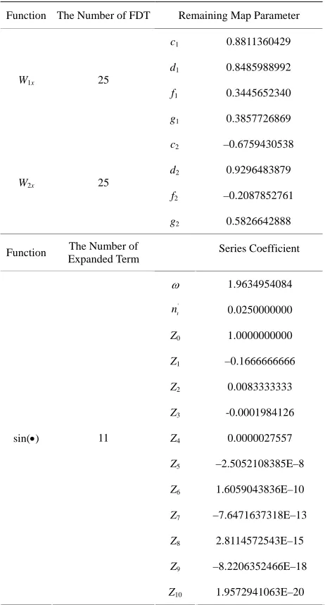
An ECG signal is measured with the modified limb lead II (ML II), and its typical waveform consists of the P- wave, QRS-complex, and T-wave. The QRS-complex pro- vides distinct information in monitoring heartbeats, which can be used to discriminate the arrhythmic types. Cen- tered on the R-wave peak, the QRS-complex can be di- vided into the Q-R segment and R-S segment (P = 2). For 50 sampling points (25 points before R-peak and 25 points after R-peak, N = N1 + N2 = 50), the remaining map parameters can be solved by Equations (7) and (8) in the Matlab workspace. By using FD between 1 and 2, the fractal patterns are constructed with Equations (5), (6), and (9). The FDTs with fractal dimension D = 1.6 is chosen in this study. For a QRS-complex of normal beat (Patient Number: MIT-103), related parameters cp, dp, fp,
and gp, p = 1, 2, are computed as shown in Table 1. The
coefficients of four terms are assigned to construct FDT functions with 4 remaining map parameters for Q-R seg- ment and R-S segment, respectively. Following the mul- tiplication and addition of the FDT, the fractal fractures can be computed. However, the logical blocks only sup- port the four fundamental operations of arithmetic. In
Equation (5), special function sin n'
D
must be ex-
panded a function into finite terms of Maclaurin series as
2 1
0
3 5
3 5
0 1 2
sin ( 1)
(2 1)!
1 1 1
3! 5! (2 1)!
r R r r R R
t t t R t
n
n D
D r
n n n n
D D D R D
z n t z n t z n t z n t
2 1 2 1
(14) where D and
11
t p D n N
, and t
constant coefficients; R, r = 0, 1, 2, , R, is the number of series term (R = 10 in this study); zr, r = 0, 1, 2,, R,
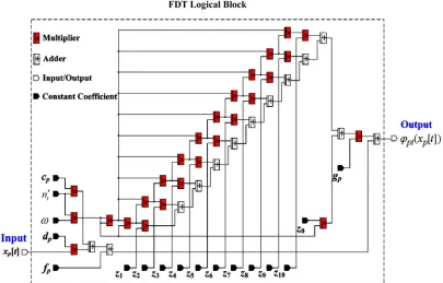
represent the series coefficients and are also constant values. These coefficients can be computed and com- pleted to verify the expanded function accuracy in the Matlab workspace, as shown in Table 1.
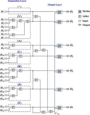
[image:4.595.308.539.304.734.2]Figure 1 shows the structure of FDT logical block, in which 13 adders, 26 multipliers, and 17 constant coefficients are required to implement each FDT. Its CLB can design the function of feature extraction with combinational logical elements, and constant coefficients are stored in the mem- ory elements. When each sampling data is applied to the FDT, each fractal feature is computed with multiplica- tion and addition. This parallelism process completes the fractal pattern, and then each feature is applied to the PNN logical block.
Table 1. Related data for FDTs.
Function The Number of FDT Remaining Map Parameter
c1 0.8811360429
d1 0.8485988992
f1 0.3445652340
W1x 25
g1 0.3857726869
c2 –0.6759430538
d2 0.9296483879
f2 –0.2087852761
W2x 25
g2 0.5826642888
Function The Number of Expanded Term Series Coefficient 1.9634954084 ' t n
n are the
0.0250000000
Z0 1.0000000000
Z1 –0.1666666666
Z2 0.0083333333
Z3 -0.0001984126
Z4 0.0000027557
Z5 –2.5052108385E–8
Z6 1.6059043836E–10
Z7 –7.6471637318E–13
Z8 2.8114572543E–15
Z9 –8.2206352466E–18
sin() 11
Figure 1. The structure of FDT logical block.
3.3. PNN Implementation with FPGA data. The optimal parameter = 0.10942 can be com- puted in the Matlab workspace. For the convergent con- dition (Squared Error 10–4), PNN converges to the nearest local minimum for less than five learning cycles. The related data of the PNN-based classifier are shown in Table 2.
In this section, we focus on classifier design and collec- tion of the annotated ECG beats for PNN training data. The ECG signals are obtained from the MIT-BIH ar- rhythmia database, including patient numbers: 100, 103, 107, 109, 111, 118, 119, 124, 200, 202, 207, 209, 212, 213, 214, 217, 221, 231, 232, and 233 [21]. ECG signals have various morphological information and waveforms, which can be classified into seven categories, including normal beat (), premature ventricular contraction (V), atrial premature beat (A), right bundle branch block beat (R), left bundle branch block beat (L), paced beat (P), and fusion of paced and normal beat (F). Centered on the R-wave peak, the QRS-complex is divided into the Q-R segment and R-S segment. The FDTs with FD are utilized to construct various fractal patterns as shown in Figure 2. With data self-similarity, the preprocess resulting in the fractal patterns are similar for the same category, which can reduce the requirement of training data. The total num- ber of fractal patterns are selected to be 1-, 6-, 2-, 3-, 4-, 4-, and 2-set data (K = 22) for the seven categories, re- spectively. These associated patterns could be expressed as weights wkiIH, k = 1, 2, 3, , 22, i = 1, 2, 3, , 50, between the input and hidden layer. The weights
HS jk
w , m = 1, 2, 3, , 7, between the hidden and summation layer are encoded as binary values with signal “1” de- noting the seven categorieswhile the rest of the weights are zero. The smoothing parameter was adjusted by using the gradient descent method with 22-set training
3.3.1. Hidden Node CLB
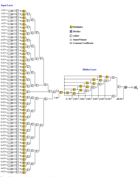
In the hidden layer, a normalized Gaussian function must be also expanded into a Maclaurin series as
1
1 d
d
0
1 2
d d d
1 2
0 1 d 2 d d
2
0 1 d 2 d d
exp
!
1 1
1
2! ( )!
r R
k k
r
R
k k k
R
k k R k
R
k k R k
E E
r
E E E
R
y y E y E y E
div
y y E y E y E
(15)
where div is dividend, div = 1 in this sudy, 12
2
and
, is the constant coefficient, and 2d 1 N
IH
k i ki
i
E
w
R is the number of series term (R = 6 in this study); yr are
Note: 1) No. 1: ; 2) No. 2~7: V; 3) No. 8~9: A; 4) No. 10~12: L; 5) No. 13~16: R; 6) No. 17~20: P; 7) No. 21~22: F.
Figure 2. The the various fractal patterns for multiple cardiac arrhythmias.
Table 2. Related data for PNN-based classifier.
Network Topology
Method
I H S O
Training
Data Learning Rate
Initial Smoothing
Parameter
PNN 50 22 8 7 22 0 1 (q = 0) = 1.0
Function The Number of
Expanded Term Related Coefficient
41.7615475105
div 1.0000000000
y0 1.0000000000
y1 1.0000000000
y2 0.5000000000
y3 0.1666666666
y4 0.0416666666
y5 0.0083333333
exp() 8
y6 0.0013888888
term can be computed with multiplication and ad-
dition. Then input the results to Gaussian function Hk.
Figure 3 shows that the structure of hidden-node CLB, 106 adders, 63 multipliers, 1 divider, and 59 constant coefficients are required to implement each node Hk.
dk
E
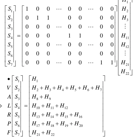
3.3.2. Summation-Node and Output-Node CLBs For seven categories, the weighting factors HS
jk
w , k = 1, 2, 3, , 22, j = 1, 2, 3, , 7, are encoded as binary val- ues with signal “1” belonging to categoryj and the rest of the factors are zero. The weighting matrix [
HS jk
w ]722 is sparse with 22 nonzero elements. The numerator of Equation (12) is a matrix vector computation, where each output Sj is formed by multiplying each of 22 outputs of
the hidden node by one of 22 weighting factors, and can be presented as
1 1 2 2 3 3 4 1 5 1 6 7 2 22 1 2 3 4 5 6 7
1 0 0 0 0 0 0
0 1 1 0 0 0 0
0 0 0 0 0 0 0
0 0 0 1 1 0 0
0 0 0 0 0 0 0
0 0 0 0 0 0 0
0 0 0 0 0 1 1
1 2 1 H S H S H S S H S H S S H H S S V S A S L S R S P S F 1
2 3 4 5 6 7
8 9
10 11 12
13 14 15 16
17 18 19 20
21 22
H
H H H H H H
H H
H H H
H H H H
H H H H
H H (16)
The number of addition and multiplication operations can be reduced leading to an increased speed in the arithmetic process. In the summation layer, the outputs of summation node Hk are computed with 15 adders. For
the same category, their outputs of hidden nodes are summed in the summation-node CLB. The implementa- tion of output node Oj would require 6 adders and 7 di-
viders, and can be presented as
1 1
2 2
3 3
4 4
1 2 3 4 5 6 7
5 5 6 6 7 7 1 O S O S V O S A O S L
S S S S S S S
[image:6.595.315.538.280.509.2] [image:6.595.56.286.340.712.2]Input Layer
Multiplier
Divider
Adder
Input/Output
Constant Coefficient
[image:7.595.57.540.75.692.2]Hidden Layer
Figure 3. The structure of hidden-node logical block.
as shown by the denominator of Equation (12), the num-ber of the addition operations can also be reduced. The
Summation Layer
Output Layer
Output Adder
[image:8.595.140.445.91.481.2]Input Divider
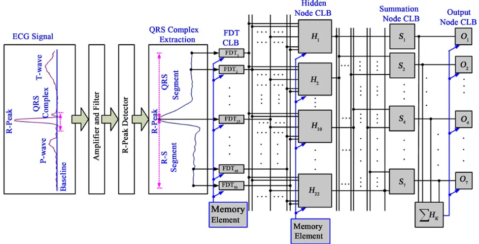
Figure 4. The structure of summation-node and output-node logical block. 3.4. Overall Structure of the Proposed Classifier
In Figure 5, the overall structure of the proposed classifier divides into three stages: 1) signal preprocessing; 2) fractal feature extraction; and 3) heartbeat recognition with PNN- based classifier. In the preprocessing stage, ECG signals are acquired by using the amplifier and filter. The band- pass filter is used to remove unwanted frequency compo- nents, which comprise supply line frequency interference (50 Hz/60 Hz), baseline wander, and muscle noises. Thus, these noises do not affect the performance of the proposed classifier. ECG records are composed by a modified limb lead II (ML II) sampled at 360 Hz. Then R-peak waves are detected by the Peak detection algorithm. It begins by scanning for local maxima in the absolute value of ECG data. For certain window, the search continues to look for next larger value. If this search finishes without finding a larger maximum, the current maximum is assigned as the R-peak wave. The averaging window was chosen to be
roughly the width of a typical QRS-complex. This window is at least 150 ms wide to allow for the wide QRS-com- plexes produced by V-heartbeats [22-24]. Centered on the detected R-peak, 25 sampling data are acquired including both Q-R segment (140 ms) and R-S segment (140 ms), respectively. In the second stage, these sampling data are converted to digital form (Signed 8-bit, 16-bit, or 32-bit Length Data) and then sent directly to the FDTs. The FDT CLBs with parallelism process are used to extract features and construct the fractal pattern. Finally, the classifier mo- dule integrates hidden-node, summation-node, and output- node CLBs for cardiac arrhythmias recognition.
4. EXPERIMENTAL RESULTS AND
DISCUSSIONS
Figure 5. The overall structure of proposed fractal patterns classifier. numbers 107, 118, 119, 200, 209, 211, 214, 217, and 231 are selected for testing. Tested ECG signals were gener- ated using LabVIEW and Matlab software on a PC Pen- tium-IV, 3.0 GHz, 480 MB RAM. The design platform of SOPC-NIOS II EDA/SOPC series (NIOS II-EP2C35 Chip, 700 K system gates, EEPROM) was used in this study. The ECG signals have been digitized and band- pass filtered, thus low- and high-frequency noises appears smaller in amplitude [21]. Signal preprocesses, such as R-peak detection and QRS-complex extraction, can be performed in LabVIEW and Matlab software. It is im- portant that the signals delivered to the FPGA must be digital type. As they are intrinsically digital formats (8-bit Format), they can be directly sent to FPGA design plat- form. For recorded (Training Data) and unrecorded data, the proposed classifier was tested with accuracy and com- putational efficiency, and compares with the results in FPGA module and Matlab workspace.
4.1. Comparison with the Fractal Patterns in FDT CLB and in Matlab Workspace
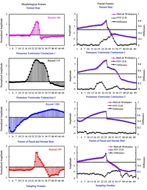
The proposed classifier is tested with the software simu- lation, in order to examine the implementation of FPGA modules. After the designated modules, the designated circuit can be programmed into the FPGA chip through the download cable. In feature extraction, fractal features are extracted by using 50 FDTs. Then 50 features are reconstructed into one fractal pattern. Since the FDT mo- dule is a simplified module, it is worth noting that each FDT function must be first examined before programming
them into the FPGA chip. The average fractal patterns from the same category are obtained from the selected patients. For training data, fractal patterns are computed by FDT module and high-level programming language (HLPL) in the Matlab workspace, respectively. Figure 6 shows the comparison fractal patterns in FDT module and Matlab workspace. The asterisk-line stands for the computed data with HLPL, and plus-sign-line is the computed data with FDT module Through cursory observation, nice inoscu- lations can be seen between them, such as the fractal pat- terns of normal heartbeat, V-heartbeat, and F-heartbeat (Pa- tient Numbers: 100, 107, 119, and 200). The differences are less than 0.2 as shown by the circle-line in Figure 6. This confirms that the proposed FDT module has high confidence of computation performance for reconstruct- ing fractal patterns.
4.2. Classification Tests
Figure 6. Compare with the fractal patterns in FDT module and in Matlab workspace. approach the desired targets for 7 categories. The output
values of the proposed classifier are shown in Figure 7.
Note: 1) No. 1: ; 2) No. 2-7: V; 3) No. 8-9: A; 4) No. 10-12: L; 5) No. 13-16: R; 6) No. 17-20: P; 7) No. 21-22: F.
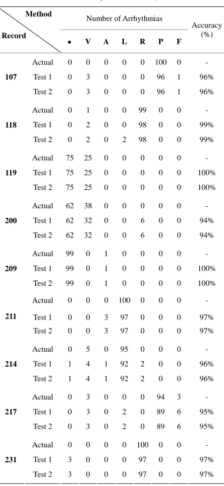
Figure 7. Output target value of the proposed classifier. Clinical diagnostic subjects have multiple cardiac ar-rhythmias such as supraventricular ectopic beat, ventricular ectopic beat, bundle branch ectopic beat, fusion, and paced beats. For example, patient number 200 has normal heart- beats and V-heartbeats with annotation labels in 1.5 mi- nute segment. Test results reveal that the accuracy is 94% as shown in Table 3. The processes recognized 38 V-heartbeats with 6 failures, and the expected sensitivity as the fraction of category V correctly classified is 84.2%, and the specificity for normal heartbeats is 100%. The results confirm that the major category is the premature ventricular contraction. Patient number 217 has V-heart- beats, P-heartbeats, and fusion heartbeats (F). As shown in Table 3, test results confirm that the major category is P. The processes recognized 94 P-heartbeats with 5 fail-ures, the sensitivities for ectopic beats is 94.7%, and the accuracy is 95%. Through the experimental tests, the pro- posed classifier can also recognize multiple cardiac ar- rhythmias with good accuracy in the FPGA module.
4.3. Discussion
In this study, the parameters of FDT functions have been directly computed by Collage theorem. Each FDT CLB has the same structure; it only assigns the segmented re- maining map parameters and series coefficients. Most of them are repeatable uses. Owing to the enhancement in features by the FDT functions, the number of training data, data storage, and processing needs can be reduced. For classification applications, artificial neural network (ANN) has been presented for this study. However, it has some limitations including very slow learning process, need iteration for updating weights, and need to determine the network architecture such as the number of hidden layers and hidden nodes. The weights, input-layer to hid- den-layer and hidden-layer to output-layer, are always non- zero values. This will increase the requirement of the addi- tion and multiplication operations and memory storage. In addition, sigmoid activation functions of hidden and output nodes [25] are difficult to implement the CLB mod-
Table 3. The results of multiple cardiac arrhythmias.
Number of Arrhythmias Method
Record
V A L R P F
Accuracy (%)
Actual 0 0 0 0 0 100 0 -
Test 1 0 3 0 0 0 96 1 96%
107
Test 2 0 3 0 0 0 96 1 96%
Actual 0 1 0 0 99 0 0 -
Test 1 0 2 0 0 98 0 0 99%
118
Test 2 0 2 0 2 98 0 0 99%
Actual 75 25 0 0 0 0 0 -
Test 1 75 25 0 0 0 0 0 100%
119
Test 2 75 25 0 0 0 0 0 100%
Actual 62 38 0 0 0 0 0 -
Test 1 62 32 0 0 6 0 0 94%
200
Test 2 62 32 0 0 6 0 0 94%
Actual 99 0 1 0 0 0 0 -
Test 1 99 0 1 0 0 0 0 100%
209
Test 2 99 0 1 0 0 0 0 100%
Actual 0 0 0 100 0 0 0 -
Test 1 0 0 3 97 0 0 0 97%
211
Test 2 0 0 3 97 0 0 0 97%
Actual 0 5 0 95 0 0 0 -
Test 1 1 4 1 92 2 0 0 96%
214
Test 2 1 4 1 92 2 0 0 96%
Actual 0 3 0 0 0 94 3 -
Test 1 0 3 0 2 0 89 6 95%
217
Test 2 0 3 0 2 0 89 6 95%
Actual 0 0 0 0 100 0 0 -
Test 1 3 0 0 0 97 0 0 97%
231
Test 2 3 0 0 0 97 0 0 97%
Note: 1) Accuracy(%) = (Nr/Nt) 100%, the overall accuracy is the fraction
of the total heartbeats correctly classified; Nr: the number of correctly
discriminated beats; Nt: total number of heartbeats; 2) Test 1 is the result in
the Matlab workspace; 3) Test 2 is the result in FPGA module.
ules, including the arithmetic process and memory stor- age. The proposed classifier provides a promising way for implementing the portable bio-monitor and telemedi- cine.
5. CONCLUSION
[image:11.595.311.537.95.584.2]rhythmias was proposed. The FDT modules are employed to construct various fractal patterns, and make the difference between normal and unhealthy subjects. The PNN mod- ule is proposed for recognizing multiple cardiac arrhythmias. Numerical experiments have been conducted with MIT- BIH arrhythmia database. The proposed classifier has ex-cellent computational efficiency, high accuracy, and flexi-bility for patterns recognition. Then programs were down- loaded to the FPGA chip to integrate all the modules, real-time processing, compression, transmission and in- put/output. This prototype can be further integrated in telemedicine and portable non-invasive devices.
6. ACKNOWLEDGEMENTS
This work is supported in part by the National Science Council of Tai-wan under contract number: NSC97-2614-E-244-001, August 1 2008- July 31 2009.
REFERENCES
[1] Hernandez, A.I., Mora, F., Villegas, M., Passariello, G. and Carrault, G. (2001) Real-time ECG transmission via internet for non-clinical applications. IEEE Transactions on Information Technology in Biomedicine, 5, 253-257.
doi:10.1109/4233.945297
[2] Mori, Y., Yamauchi, M. and Kaneko, K. (2000) Design and implementation of the vital sign box for home heal- thcare. Proceeding of IEEE EMBS International Confer-ence on Information Technology Applications in Bio-medical, Arlington, 9-10 November 2000, 104-108. [3] Guillen, J.M., Millet, J. and Cebrian, A. (2001) Design of
a prototype for dynamic electrocardiography monitoring using GSM technology: GSM-holter. Proceeding of 23rd Annual International Conference-IEEE/EMBS, Istanbul, 25-28 October 2001.
[4] Chris, D. and Fred, H. (2000) FPGA signal processing using sigma-delta modulation-innovative combinations of techiques and hardware for system designers. IEEE Sig-nal Processing Magazine, January, pp. 20-35.
[5] Abbes, A. and Shrutisagar, C. (2007) Power modeling and efficient FPGA implementation of FHT for signal processing. IEEE Transactions on Very Large Scale In-tegration Systems, 15, 286-295.
doi:10.1109/TVLSI.2007.893606
[6] Huang, S.-J., Yang, T.-M. and Huang, J.-T. (2002) FPGA realization of wavelet transform for detection of electric power system disturbances. IEEE Transactions on Power Delivery, 17, 388-394. doi:10.1109/61.997905
[7] Chilo, J. and Lindblad, T. (2008) Hardware implementa-tion of ID wavelet transform on an FPGA for infrasound signal classification. IEEE Transactions on Nuclear Sci-ence, 55, 2008, pp. 9-13.
doi:10.1109/TNS.2007.914322
[8] Tiwari, A. and Tomko, K.A. (2005) Enhanced reliability of finite-state machines in FPGA through efficient fault detection and correction. IEEE Transactions on
Reliabil-ity, 54, 459-467. doi:10.1109/TR.2005.853438
[9] Kim, D. (2000) An implementation of fuzzy logic con-troller on the reconfigurable FPGA system. IEEE Trans-actions on Industrial Electronics, 47, 703-715.
doi:10.1109/41.847911
[10] Chen, D.R., Chang, R.F., Chen, C.J., Ho, M.F., Kuo, S.J., Chen, S.T., Hung, S.J. and Woo, K.M. (2005) Classifica-tion of breast ultrasound images using fractal feature.
Clinical Imaging, 29, pp. 235-245.
doi:10.1016/j.clinimag.2004.11.024
[11] Katz, M. (1988) Fractals and the analysis of waveforms.
Computing in Biology and Medicine, 18, 145-156.
doi:10.1016/0010-4825(88)90041-8
[12] Mazel, D.S. and Hayes, M.H. (1992) Using iterated func-tion systems to model discrete sequences. IEEE Transac-tion on Signal Processing, 40, 1724-1734.
doi:10.1109/78.143444
[13] Vines, G. and Hayes, M.H. III (1993) Nonlinear address maps in a one-dimensional fractal model. IEEE Transac-tions on Signal Processing, 41, 1721-1724.
doi:10.1109/78.212754
[14] Barnsley, M. (1986) Fractal functions and interpolation.
Constructive Approximation, 2, 303-329.
doi:10.1007/BF01893434
[15] Seng, T.L., Khalid, M. and Tusof, R. (2002) Adaptive GRNN for the modeling of dynamic plants. Proceedings of the 2002 IEEE International Symposium on Intelligent Control, Vancouver, 27-30 October 2002, 217-222. [16] Lin, C.-H. and Wang, C.-H. (2006) Adaptive wavelet
networks for power quality detection and discrimination in a power system. IEEE Transactions on Power Delivery, 21, 1106-1113. doi:10.1109/TPWRD.2006.874105
[17] Lin, C.-H. Du, Y.-C. and Chen, T.S. (2008) Adaptive wavelet network for multiple cardiac arrhythmias recog-nition. Expert Systems with Applications, 34, 2601-2611.
doi:10.1016/j.eswa.2007.05.008
[18] Fawcett, B.K. (1994) Tools to speed FPGA development.
IEEE Spectrum, 31, 88-94. doi:10.1109/6.328732
[19] Anderson, I.D.L. and Khalid, M.A.S. (2009) SC build: A computer-aided design tool for design space exploration of embedded central processing unit cores for field-pro- grammable gate arrays. IET Computer Digital Techniques, 3, 24-32. doi:10.1049/iet-cdt:20070120
[20] Arshak, K., Jafer, E., McDonagh, D. and Ibala, C.S. (2007) Modeling and simulation of wireless sensor sys-tem for health monitoring using HDL and simulink mixed environment. IET Computer Digital Techniques, 1, 508- 518. doi:10.1049/iet-cdt:20050206
[21] Goldberger, A.L., Amaral, L.A.N., Glass, L., Hausdorff, J.M., lvanov, P.Ch., Mark, R.G., Mietus, J.E., Moody, G.B., Peng, C.K. and Stanley, H.E. (2000) PhysioBank, physio toolkit, and PhysioNet: Components of a new re-search resource for complex physiologic signals. Circula-tion, 101, e215-e220.
[22] Urrusti, J.L. and Tompkins, W.J. (1993) Performance evaluation of an ECG QRS complex detection algorithm.
28-31 October 1993, 800-801.
[23] Nambakhsh, M.S., Tavakoli, V. and Sahba, N. (2008) FPGA-core defibrillator using wavelet-fuzzy ECG ar-rhythmia classification. Proceeding of 30th Annual In-ternational IEEE EMBS Conference, Vancouver, 20-24 August 2008, 2673-2676.
[24] Shukla, A. and Macchiarulo, L. (2008) A fast and
accu-rate FPGA based QRS detection system. Proceeding of
30th Annual International IEEE EMBS Conference, Van- couver, 20-24 August 2008, 4828-4831.
[25] Rzempoluck, E.J. (1998) Neural networks data analysis using SimulnetTM. Springer-Verlag Inc., New York.