777
©IJRASET: All Rights are Reserved
3D Printer
Akshay Shinde
1, Kashish Parmar
2, Roshan Bhuvad
3,
Madhav Pai
4, Prof. Mahalaxmi Palinje
5, Prof. Disha Bhosle
61, 2, 3U.G. Student, Department of Electronics And Telecommunication, Atharva College of Engineering, Mumbai, Maharashtra,
India
4, U.G. Student, Department of Electronics, Atharva College of Engineering , Mumbai, Maharashtra, India
5Associate Professor, Department of Electronics And Telecommunication, Atharva College of Engineering, Mumbai, Maharashtra,
India
6Associate Professor, Department of Electronics, Atharva College of Engineering, Mumbai, Maharashtra, India
Abstract: This project represents the design, construction and development of 3D printer. According to the study of comparing traditional manufacturing methods for producing components, organic methods are implemented. The idea of this project is entirely based on controlling the motor for full steering across each axis. This Project utilizes ARDUINO MEGA to control the entire circuitry.
The proposed design fulfills the need of artificial parts or Model. This 3D Printer is based on the technology of the FUSED DEPOSITION MODELING. It extrudes plastic filament from a nozzle and deposits molten plastic along planned paths layer by layer until a part is completed.
Thus creating the exact prototype of the model created on CAD software. 3D Printing is accelerating innovative technology, minimising material usuage but developing actual 3D model.
Keywords: Fused deposition Modelling, Arduino Mega, 3D Printer, Prototype, CAD software, Filaments.
I. INTRODUCTION
In today's generation, a new additive technology has been invented which is known to be very promising and is called rapid prototyping also called as additive manufacturing technology. This technology is innovative and made useful for many fields like researchers, manufacturers, designers, engineers and scientists.
Collaborating different fields in single package formed 3D printer as it includes Design, manufacturing, electronics, materials and business [1]. In 3D printer the object is created layer by layer with the suitable material in three dimension formations. The difference between traditional manufacturing and 3D printing is that the 3D printer involves additive approach but most of the traditional manufacturing processes involve subtractive approach that includes a combination of grinding, bending, forging, moulding, cutting, gluing, welding and assembling.
At the beginning 3D printing was mostly seen as a tool to shape and bring subjective designs but recently this technology is developing for a need of mechanical components and some required parts which can be printed. It completely changes not only the industrial/manufacturing field, but also our educational sector in future as a 3D printer can make a complete prototype in a single process [2].
II. LITERATURESURVEY
A. In current days, improvement in technology before us is a result of advancement in the Research and Development process by great minds. It is shown as "sophistication" in every field like at your workplace, household activities, multimedia, entertainment or medications, where in connection and smart tabs ensure that the task is completed. This "sophistication" is a result of "convergence" of new Technologies.
B. 3D Printing Technology development should help people to do their work more easily and make them comfortable [4].
C. Printer control using Mobile device is a useful technology that will help people in their day to day life. The conventional printer requires Mobile as input device, LAN connection and the printer as an output device. The idea of using Mobile phone to printing data using wireless technology. Mobile phone should contain Bluetooth through which user can able to print data [5].
778
©IJRASET: All Rights are Reserved
III.DESIGNANDCOMPONENTS
1) Arduino Mega 2560: A board that is derived from ATmega2560. There are numerous I/O pins. There are 54 pins (where in 15 are PWM outputs, analog inputs=16, 4 UARTs, serial ports. It also has a crystal oscillator of 16 MHz. It has a USB connection, power jack and a button which is used to reset. It has great performance with most of the shields. It is basically a micro-controller.
[image:2.595.125.457.223.341.2]2) Stepper Motor: It is a DC motor which works in steps consisting brushless motor, with synchronous full rotation and is divided into some discrete steps. The 2 foremost additives of a stepper motor are the rotor and the stator. The rotating shaft is rotor and the stator consists of electromagnets that form the stationary motors part.
Figure 1: Stepper Motor NEMA17 Figure 2: Extruder
3) SMPS: SMPS is called as a switched mode power supply. It is operated at high frequencies. It converts the power through switching devices. SMPS has high efficiency. They are used in various electronic projects and computers that demand stable power supply.
4) Motor Driver: It is a bipolar stepper motor with current limiting features and protection on temperature. It works on 6 micro step resolutions (1/32 step). It functions from 8.2V to 45V, delivering 1.5A phase without heat sink ( and 2.2A / coil). It implements pinout and interface for better performance.
5) Extruder: It is the fundamental component of our project. It has a responsibility of passing right quantity of filament to the melting hot end, which is extruded into layers to make the model. Extruder is not similar to the Hot end. It is the "cold end" as the filament is cold. It acts as a medium between the filament and the hot end.
6) Temperature Sensor: It consists of “Resistance Temperature Detectors" which function similar to thermistors in operation. They are made of metals like Platinum either copper or nickel. PT100 is used most widely for 3D Printers, consisting of a resistance of 100Ὡ at 0℃
[image:2.595.182.428.527.715.2]IV.IMPLEMENTATIONOFTHESYSTEM
779
©IJRASET: All Rights are Reserved
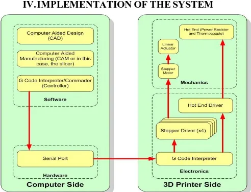
The block diagram shows mainly two sides. First is Computer side and the other is Printer side.
A. Computer Side
1) (CAD) Computer Aided Design: Here the 3D model of the object is to be printed in designed. There are many softwares that can be utilized to build the model. In this project Sketchup is used. Once the model is done it is saved as .stl or .obj file.
2) (CAM) Computer Aid Manufacturing: The software such as Slicer is used to break down the complete model into several layers. These layers could be hundreds.
3) G-code Creator: Here the entire model is converted into g codes in order to create a path across the XYZ axis. G-code is inbuilt in the CAM softwares. The model is converted into G-code by the manual command.
4) Serial Port: A USB connector is used to connect the PC to the Printer. It is used for the communication between the PC and the Printer. The communication is bidirectional.
B. Printer Side
1) Controller: It works as a interpreter of G-code. The G-code is read and Drives the stepper motor along the axis as planned. Appropriate microstepping signals are sent to the motor through the driver. It also send the signals to the hot end driver.
2) Stepper Driver: This driver is used to provide the full 12v to the motor whenever the high logic is sent to it by the controller. 5v controller logic is not capable to drive the motor, hence provides the 12v to it in response to the high logic.
3) Stepper Motor: These motors are DC motor with an angular movement. Each motor is responsible to each of the axis XYZ. As the motor moves the Axial shift happens due to the pulley and conveyor belt mechanism. Even though the motor posses the rotary movement the end movement is linear in nature.
4) Hot End and Thermistor: Hot end is also known as the Extruder. The filament is heated and pours the molten plastic along the path. Thermistor is a temperature sensor used to sense the temperature of the Extruder.
V. WORKING
1) The working of the 3D Printer is based on the based on the principle of the fused deposition along the XYZ axis on the path created by the computer with the help of the G-code. The whole object is formed as the molten plastic is being poured on the path layer by layer.
2) The 3D model of the object to be printed is made on the CAD software then it is saved as .stl or .obj file. Then several layers are formed with the help of the CAM Software by slicing. The same software converts these layers into G-Codes. These codes are sent to the printer through the serial port.
3) The codes sent by the PC are fed to the controller i.e. Arduino Mega. Arduino Mega is extended by the RAMPS shield. Stepper motor driver are mounted on the shield. X and Y axis uses one motor each and Z axis motor use 2 motors. These motors are powered by the SMPS. The controller will drives the motors along the path and will send the heating signal to the Extruder which will heat the PLA filament and the molten plastic will be poured on the path. This process will continue till the last layer of the model. At the end required object will be formed.
780
©IJRASET: All Rights are Reserved
VII. RESULTS
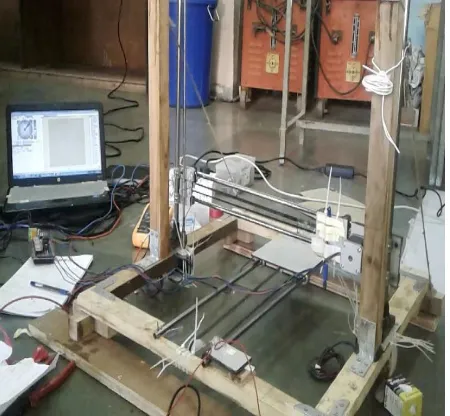
[image:4.595.302.539.207.417.2]This is the actual prototype of our working model. We have successfully created a model block of 2cm x 2cm x 2cm, using ABS filament whose melting temperature is 220o C - 230o C. We control the machine using the Repetier Host software. All the functions of extruder, temperature, heating, fan, controlling all the X, Y, Z axis manually can be managed using these software’s. Once the extruder is set to the temperature, object is loaded and printing is started. Hence the machine prints the object layer by layer according to the G code file provided. It can print upto the Bed size of 30 x 30 x 30 cm. Hence an actual 3D model is created from the CAD software.
Figure 4. Prototype of 3D Printer Figure 5. Cube of 2cm printed
VIII. SPECIFICATIONS
A. Cartesian Model
B. Fused Deposition Modelling Technology (FDM)
C. Marlin Firmware
D. Build Dimensions Max : 32 X 32 X 30 cm
E. PLA, ABS and other material support
F. Filament Dimension Max: 1.75mm
G. Nozzle Diameter : 0.4mm
H. Temperature Max: 275 deg C
I. 2D Plotting, Laser cutting, Milling, PCB, CNC support
J. Costing : 15,000 INR
IX.CONCLUSION
Now as we know, 3D printer has wide range of advantages and applications, hence we decided to work for this project and upgrade our skills for the latest innovative technology. So initially we found the origin and history of 3D Printer, of how it is to be made, what technology can be used, what is the complete procedure. Explaining the Introduction in the 1st part we then explained the Literature survey conducted. Further the Components and design necessary for the project are studied. Implementing the Printer using FDM Technology was a learning experience. 3D Printing has tremendous potential and can bring a revolution to our entire industry. It can lead upto Socio-Economic benefits for the world.
[image:4.595.43.268.210.418.2]781
©IJRASET: All Rights are Reserved
REFERENCES
[1] Bob Hayward, David Moschella, Jon Schreiber, Simon Wardley, Howard Smith, “3D printing and the future of manufacturing” CSE, the rise of 3D printing. [2] Chris Anderson, Makers: The new industrial revolution (New York: Crown Business, 2012), p. 210.
[3] Olawuyi J.O. Mgbole Friday, “Technological Convergence” Science Journal of Physics, pp.7237-7242, 2012.
[4] Stefan Nowak, Falk-Moritz Schaefer “Towards a Convergent Digital Home Network Infrastructure” IEEE Transactions on Consumer Electronics, pp. 1695-1703, 2011.
[5] Amarnath M, “Home appliance control using mobile cloud technology” Proceedings of International Conference on Modeling Optimisation and Computing, pp. 3587-3595, 2012.
[6] Gerald C. Anzalone1 , Chenlong Zhang1 , Bas Wijnen1 , Paul G. Sanders1 , And Joshua M. Pearce2 GeraldC. Anzalone1 , Chenlong Zhang1 , Bas Wijnen1 , Paul G. Sanders1 , And Joshua M. Pearce2 Digital Object Identifier10.1109/Access.2013.2293018
[7] HtinLinOo1KyawZawYe,YeHtetLinn”ModelingandControllingofTemperaturein3DPrinter(FDM)”National ResearchUniversityof Electronic Technology Zelenograd, Moscow,Russia.
[8] MedhaviKamaran, AbhishekSaxena “A Comprehensive Study on 3D Printing Technology” MIT International Journal of Mechanical Engineering, Vol. 6, No. 2, August 2016.
[9] Thabiso Peter Mpofu, CephasMawere, Macdonald Mukosera “The Impact and Application of 3D Printing Technology” International Journal of Science and Research (IJSR) ISSN (Online): 2319-7064 Impact Factor (2012): 3.358.