ISSN Online: 2164-5655 ISSN Print: 2164-5612
DOI: 10.4236/ojcm.2018.83009 Jul. 19, 2018 110 Open Journal of Composite Materials
Effect of Needle Punching Process on a Chopped
Strand Mat Composite with an Open Hole
Daiki Ichikawa
1, Hiroyuki Hamada
2, Akio Ohtani
31Graduate School of Kyoto Institute of Technology, Kyoto, Japan
2Future-Applied Conventional Technology Center, Kyoto Institute of Technology, Kyoto, Japan 3Faculty of Fiber Science and Engineering, Kyoto Institute of Technology, Kyoto, Japan
Abstract
The easiest and most reliable joining method is the mechanical joint with a bolt and nut or rivet. However, in the case of composite laminates, mechanical joint properties decrease because of lower interlaminar properties compared to in-plane properties around hole. This study investigated needle punching process with the aim of improving the mechanical properties in the thickness direction of fiber-reinforced plastic composite laminates with an open hole. Needle punching process was applied to glass fiber chopped strand matused as the reinforcement for the composite laminates. Open-hole tensile tests and observations of end cross-sections after the tests were performed. The tensile properties and fracture mechanism of the specimens subjected to needle punching process were investigated. In addition, characteristic distance (a pa-rameter for evaluating resistance to fracture in open-hole tensile test speci-mens) was also calculated to examine the effects of needle punching process conditions on fracture toughness. Tensile strength was improved by more than 15% by needle punching process. However, when a certain needle punching density was exceeded, the mechanical properties worsened. In addi-tion, characteristic distance increased with increasing needle punching densi-ty. Thus, these results suggest that there is an optimal needle punching density with respect to strength and characteristic distance.
Keywords
Fiber-Reinforced Plastic, Needle Punch, Chopped Strand Mat, Open Hole, Characteristic Distance
1. Introduction
In recent years, fiber reinforced plastic (FRP) composites, which offer high
spe-How to cite this paper: Ichikawa, D., Hamada, H. and Ohtani, A. (2018) Effect of Needle Punching Process on a Chopped Strand Mat Composite with an Open Hole. Open Journal of Composite Materials, 8, 110-123.
https://doi.org/10.4236/ojcm.2018.83009
Received: May 13, 2018 Accepted: July 16, 2018 Published: July 19, 2018
Copyright © 2018 by authors and Scientific Research Publishing Inc. This work is licensed under the Creative Commons Attribution International License (CC BY 4.0).
DOI: 10.4236/ojcm.2018.83009 111 Open Journal of Composite Materials
cific strength and high specific rigidity, have been used in a wide variety of fields, ranging from large passenger aircraft such as the Boeing 787 to vehicles and sports equipment. When composites are used in various applications such as these, they need to be joined with other members, the same as in the case of metal materials. Joints of metal materials are made by welding or by creating holes and using mechanical joints such as bolts or rivets. However, in the case of composite materials, the strength of joints made using welding or adhesives is not especially high, and there are problems with long-term durability and prod-uct management if adhesives are used [1] [2] [3]. Because of this, mechanical joints are said to have relatively high reliability for composite materials. Howev-er, there are items of concern even for mechanical joints of composite materials. When stress concentrates around mechanical joints in composite laminates, lo-cal fracture can occur together with delamination, and the load bearing capacity of the entire structure suddenly decreases [4]. Because of this, improvement of interlaminar characteristics is necessary in order to improve the mechanical characteristics of mechanical joints in composite laminates. Although various studies have investigated ways to improve the interlaminar characteristics of composite laminates [5] [6] [7] [8] [9], here we focused on applying needle punching process to the reinforcement of the composite material as means of improving these characteristics. Needle punching process is a fabric processing method that is used to create non-woven fabric and is able to create interlacing of fabrics in the thickness direction by piercing cottony fiber with special barbed needles called felting needles. When this technique is used to strengthen compo-site materials, it is thought to improve the interlaminar characteristics of stacked layer materials by causing fibers to be oriented in the thickness direction, and to suppress delamination due to stress concentration around holes. Previous re-search applying the needle punching technique to the reinforcement of compo-site materials has been conducted, for example, applying needle punching process to glass fiber chopped strand mat (CM) and testing the tensile properties of composite reinforced using this reinforcement [10]. Another study has inves-tigated the mechanical properties of composite using non-woven fabrics and woven fabrics made from glass fiber with application of needle punching process
[11]. However, no study has examined the effects of holes on the mechanical properties of composites using a reinforcement subjected to needle punching process.
DOI: 10.4236/ojcm.2018.83009 112 Open Journal of Composite Materials
process conditions on characteristic distance.
2. Methods
2.1. Fabrication of Reinforcement
A needle punching glass chopped strand mat (NCM) was used in this research. It is a reinforcement formed by applying needle punching process using felting needles to CM (weight: 450 g/m2: MC 450A, Nitto Boseki Co., Ltd.). Figure 1
[image:3.595.207.539.432.709.2]shows pictures and schematics of the felting needles used to fabricate NCM, and
Table 1 shows the details of each needle. This research used three types of felting needles (labeled A, B, and C) (Groz-Beckert KG) with different needle thick-nesses and shapes of barbs attached to the needle surface. Felting needle A is a #25 needle (needle thickness: 0.85 mm) with a kick-up, felting needle B is a #32 needle (needle thickness: 0.68 mm) with a kick-up, and felting needle C is a #25 needle without a kick-up. The kick-up is a part that protrudes outside the thick-ness of the needle as shown in Figure 1. During needle punching process, fibers are hooked by the barbs and become oriented in the thickness direction. When a kick-up is present, the amount of fibers hooked by the needle is expected to in-crease.
NCM was fabricated by installing needle punching plates fitted with each of the three different types of felting needles into a non-woven fabric manufactur-ing device (Needle room NH-380:Daiwa-kiko Co., Ltd.). NCM was needle punch processed by feeding two layers of CM simultaneously into the non-woven fabric
Table 1. Details of the felting needles.
Needle Barbs shape Kick-up Thickness of the needle (mm)
A ① 〇 0.85
B ① 〇 0.68
C ② × 0.85
DOI: 10.4236/ojcm.2018.83009 113 Open Journal of Composite Materials
manufacturing device along the longitudinal direction of the CM base material rolls. The needle depth was set to 15 mm and the reinforcement feed rate was set to 7, 9, 12, 15, and 17 (mm/count). The needle depth is the depth to which the felting needles penetrate the reinforcement with each punch, and the feed rate is the length by which the reinforcement is fed after each punch. The density per unit area of needle punching process is calculated from Equation (1) using the reinforcement feed rate [14].
0 n N m
L
= ⋅ (1)
here, N [holes/cm2] is the needle punching density, L [mm/count] is the feeding
speed, m [m] is the length of the metal plate with felting needles, and n0 [G/m2]
is the number of needles per unit area. In this research, we fabricated NCM with different needle punching density by changing the reinforcement feeding speed in five steps while retaining the same fabrication conditions used in previous re-search [15]. Furthermore, since there are many types of NCM in this study, the reinforcement name is defined as the combination of the needle type (A, B, C) and the needle punching density (12.3, 13.9, 17.4, 23.2, 29.9 holes/cm2). For
ex-ample, A-12.3 is the reinforcement fabricated using felting needle A at a needle punching density of 12.3 holes/cm2.
2.2. Specimen Preparation and Testing Method
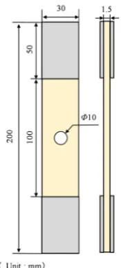
The specimens used in this study were formed by using the hand layup method using unsaturated polystyrene resin (RIGOLAC: 150HR BQNTNA, SHOWA DENKO Co., Ltd.) as the matrix resin. After forming, a weight was placed on top and a pressure of 9 kPa was applied. Furthermore, a spacer was used so that the thickness of each specimen was around 1.5 mm. The fiber volume fraction was around 20%. After the resin was cured at room temperature for 24 h, post curing was performed for 2 h in a 100˚C thermostatic bath to complete the curing. Af-ter forming, the specimens were cut into strips using a compact universal cutting machine (MC-120, Maruto Instrument Co., Ltd.). Figure 2 shows the dimen-sions of the specimens. A hole of diameter 10 mm was drilled in the center of the specimens with drill press and an ultra-hard drill for FRP (HAM-342, HAM Ja-pan Co., Ltd.).
2.3. Test Method
The open hole tensile test was performed using a universal tester (Type 5949, In-stron Co., Ltd.). The test conditions were test speed of 1 mm/min and spacing between grips of 100 mm. The tensile strengths of the specimens with a hole were found by using Equation (2).
(
W D TP)
σ =− (2)
here, σ [MPa] is the tensile strength with a hole, P [N] is the maximum load, W
DOI: 10.4236/ojcm.2018.83009 114 Open Journal of Composite Materials
Figure 2. Schematic of specimens.
specimen thickness. Furthermore, video was captured using a digital single-lens reflex camera (α5100, SonyCo., Ltd.) to observe the fracture propagation beha-vior during the open hole tensile test.
After the open hole tensile test, the end cross-sections of the specimens were observed in order to investigate the fracture mechanism. Cross-sectional polish-ing to a mirror finish was performed uspolish-ing a table-top sample polisher (IM-P2, IMTCo., Ltd.) with waterproof abrasive paper and alumina powder. The cross-sections were observed using an inverted metallurgical microscope (GX41, OlympusCo., Ltd.).
2.4. Evaluation by Characteristic Distance
Evaluation by characteristic distance is based on the point stress criterion pro-posed by Whitney et al. for assessing the strength of open hole tensile test spe-cimens [16]. This criterion is explained in Figure 3. According to this criterion, ultimate failure of a specimen with an open hole occurs when the region with tensile stress (σy) exceeding the tensile strength of the material (σ0) in the
mini-mum cross-section of the specimen progresses a distance (ROT) from the hole
edge under a tensile load. This distance ROT is called the characteristic distance.
Thus, fracture occurs when the stress value along ROT reaches the tensile strength
of the material. In other words, a material with a hole is more resistant to frac-ture when the characteristic distance is longer. In this study, stress around the hole at fracture was found by finite-element method (FEM) stress analysis (Marc Student Edition 2016.0.0, MSC Software Co., Ltd.), and the characteristic dis-tance ROT was found by applying point stress criterion theory to the obtained
stress distribution. Specifically, the characteristic distance ROT was calculated by
finding the distance from the hole edge to the location where the tensile stress (σy) distribution in the minimum cross-section at the fracture load (PNT) on the
DOI: 10.4236/ojcm.2018.83009 115 Open Journal of Composite Materials
(σ0). PNT and σ0 were actually measured, and the σy distribution was found by
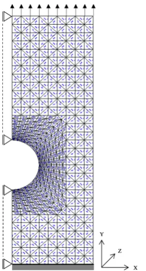
FEM stress analysis as described above. Figure 4 shows the FEM model that was used. This model was 2-dimensional and composed by plane strain element, and converted into a half-model by making use of the symmetry. Linear analysis was performed assuming plane strain conditions by applying forced displacement.
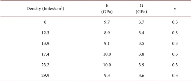
Table 2 shows the material constants that were used. The longitudinal elastic modulus (E) was calculated from tensile tests of flat smooth material without any holes, and Poisson’s ratio (ν) was fixed at 0.3. Furthermore, the modulus of rigidity (G) was calculated using Equation (3).
(
)
2 1 E G
v
=
[image:6.595.292.454.212.394.2]+ (3)
Figure 3. Description of the point stress criterion.
[image:6.595.299.450.426.705.2]DOI: 10.4236/ojcm.2018.83009 116 Open Journal of Composite Materials
Table 2. Parameters used for FEM.
Density (holes/cm2) E
(GPa) (GPa) G ν
0 9.7 3.7 0.3
12.3 8.9 3.4 0.3
13.9 9.1 3.5 0.3
17.4 10.0 3.8 0.3
23.2 10.0 3.9 0.3
29.9 9.3 3.6 0.3
The contact point at the lower edge of the specimen was fixed, and the contact point at the upper edge of the specimen was forcibly displaced until reaching PNT/2 overall.
3. Results and Discussion
3.1. Open Hole Tensile Test
Figures 5-7 show representative stress-strain curves of specimens that had been subjected to needle punching process using felting needles A, B, and C, respec-tively. These stress-strain curves show that fracture strain was increased by needle punching process with all of the felting needles. Furthermore, the stress at fracture was often observed to be higher than that of CM.
Figure 8 shows the relationship between tensile strength and needle punching density for each specimen of the NCM composites. The material with needle punching density 0 holes/cm2 is the CM composite. The NCM composites
exhi-bited essentially the same trend regardless of the type of felting needle, with the strength initially increasing with increasing needle punching density and then decreasing at a needle punching density of 17.4 holes/cm2 or higher.
DOI: 10.4236/ojcm.2018.83009 117 Open Journal of Composite Materials
[image:8.595.263.483.293.478.2]Figure 5. Stress-strain curves (felt needle A).
Figure 6. Stress-strain curves (felt needle B).
Figure 7. Stress-strain curves (felt needle C).
0 20 40 60 80 100 120
0 0.005 0.01 0.015 0.02
St re ss (M Pa ) Strain (-) CM NCM-12.3 NCM-13.9 NCM-17.4 NCM-23.2 NCM-29.9 0 20 40 60 80 100 120
0 0.005 0.01 0.015 0.02
St re ss (M Pa ) Strain (-) CM NCM-12.3 NCM-13.9 NCM-17.4 NCM-23.2 NCM-29.9 0 20 40 60 80 100 120
0 0.005 0.01 0.015 0.02
[image:8.595.265.486.516.703.2]DOI: 10.4236/ojcm.2018.83009 118 Open Journal of Composite Materials
Figure 8. Relationship between tensile strength and needle
punching density.
Although these results show that the different types of felting needles had some effect on the tensile properties, because no large differences were found in the observed trends, subsequent studies were performed using only the NCM composite fabricated using felting needle A, which exhibited the highest tensile strength.
Next, differences in fracture propagation behavior were investigated by using video of the area around the hole recorded during tensile tests. Figure 9 shows photos of the external appearance of the CM composite and the NCM-17.4 and NCM-29.9 specimens that were fabricated using felting needle A as representa-tive examples during fracture propagation and after break off. For both the CM and NCM composites, cracking initiated and progressed from the edge of the hole as the load was increased. However, after this, the fracture mechanism ob-served in the CM composite involved cracking in a fan shape, whereas the cracking was relatively straight in the NCM composites. The same fracture propagation behavior was observed in NCM composites even when the needle punching density was different. These observed trends in fracture propagation behavior were consistent with those observed in previous research [15].
Next, end cross-sections of the specimens were observed. Figure 10 shows a schematic diagram of the cross-sectional observation area, and Figure 11 shows cross-sectional photos and schematic diagrams of the CM, NCM-17.4, and NCM-29.9 specimens. For the CM composite, a fracture mechanism was ob-served that involved a small number of transverse cracks and delamination.
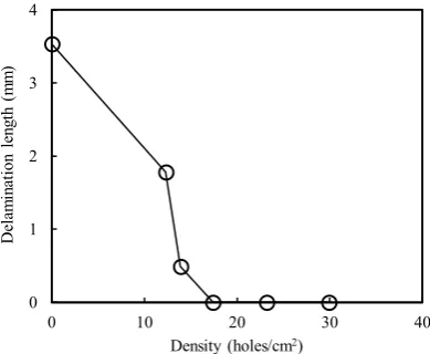
The number of transverse cracks in the end cross-section of the specimen af-ter each test and the length of delamination were quantified from the cross-sectional observation results in Figure 11. Figure 12 shows the relation-ship between the number of transverse cracks and needle punching density, and
Figure 13 shows the relationship between delamination length and needle punching density. These results show that the number of transverse cracks in-creases and the delamination length dein-creases with increasing needle punching
0 20 40 60 80 100
0 10 20 30 40
Te
ns
ile
s
tre
ngt
h
(M
Pa
)
Density (holes/cm2)
DOI: 10.4236/ojcm.2018.83009 119 Open Journal of Composite Materials
density.
[image:10.595.288.459.356.581.2]In light of the above results, we next investigated differences in fracture prop-agation behavior depending on whether or not needle punching process was performed. Figure 14 shows schematic diagrams of fracture progression in the CM composite. In the CM specimen, a crack at the edge of the hole propagated perpendicular to the load direction. As this cracking propagated, transverse crack occurred and propagated in the thickness direction around the tip of the fissure, and delamination is thought to have occurred when this crack tip reached interface between the layers. As the crack propagates from the edge of the hole, the area where transverse cracks and delamination occur grows ac-companying delamination due to the transverse cracks. Then, fan-shaped cracks form at ultimate failure. In contrast, it is thought that the number of transverse cracks was larger in the NCM composites than in CM composite because the number of points from which transverse cracks initiated increased due to the dispersion of fiber bundles as the number of fiber bundles oriented in the thick-ness direction increased. However, the fiber bundles oriented in the thickthick-ness direction suppressed the occurrence of delamination, and therefore fracture propagation followed a relatively straight path.
Figure 9. Differences in fracture propagation behavior around the
hole for the CM, NCM-17.4, and NCM-29.9 specimens.
[image:10.595.290.447.628.703.2]DOI: 10.4236/ojcm.2018.83009 120 Open Journal of Composite Materials
Figure 11. Cross-sectional observation of the fracture surface of the CM,
[image:11.595.269.478.69.293.2]NCM-17.4, and NCM-17.4 specimens with an open hole.
Figure 12. Relationship between number of transverse cracks and needle
punch-ing density.
Figure 13. Relationship between delamination length and needle punching density.
0 20 40 60 80 100
0 10 20 30 40
N
um
be
r
of
tr
an
sv
er
se
c
ra
ck
s (
-)
Density (holes/cm2)
0 1 2 3 4
0 10 20 30 40
D
ela
m
in
atio
n
le
ng
th
(
m
m
)
[image:11.595.275.471.336.495.2] [image:11.595.276.471.547.707.2]DOI: 10.4236/ojcm.2018.83009 121 Open Journal of Composite Materials
Figure 14. Changes in fracture propagation around the hole for a CM specimen.
Next, we discuss the reason for the variation in mechanical properties de-pending on the needle punching density as shown in Figure 8. Increasing strength with increasing needle punching density may be attributable to the ef-fect of the larger dispersion of fibers. Previous research has found that the dis-persion of fibers was promoted by needle punching process [17] [18]. Therefore, the tensile properties are thought to have been improved by the elimination of resin-rich areas and the reduction of variation in the stress distribution as a re-sult of the increasing dispersion of fibers by needle punching process. However, the amount of fibers oriented in the in-plane direction decreased and the rein-forcing fibers became shorter with increasing needle punching density, and the number of transverse cracks increased as the dispersion of fibers and the number of fiber bundles in the thickness direction increased. Thus, it is thought that the mechanical properties worsened when the needle punching density was in-creased too greatly.
3.2. Characteristic Distance under Tensile Load
Figure 15 shows the relationship between the open hole tensile strength and characteristic distance (ROT) in NCM composites fabricated using felting needle
A. The plotted black circles show results for the CM composite. At a needle punching density of 12.3 holes/cm2, the strength was essentially unchanged and
ROT was shorter than that of the CM specimen. After this, the strength and ROT
increased with increasing needle punching density, and at a needle punching density of 23.2 holes/cm2, both the strength and characteristic distance exceeded
those of the CM specimens. As the needle punching density was then further in-creased, ROT increased but strength decreased. These results show that needle
DOI: 10.4236/ojcm.2018.83009 122 Open Journal of Composite Materials
Figure 15. Relationship between tensile strength and characteristic distance.
the rapid propagation of delamination being suppressed by fiber bundles oriented in the thickness direction as a result of needle punching process, as shown in Fig-ure 14. These results show that there is an optimal needle punching density not only for strength, but also for resistance to failure when a hole is present.
4. Conclusions
This study investigated the effect of needle punching process conditions on the tensile properties and fracture propagation behavior of composite laminates with a hole. In addition, we investigated the characteristic distance, which is an important parameter for evaluating the resistance of open hole tensile test spe-cimens to failure.
It was found that the tensile strength of composite materials with a hole could be increased by increasing the dispersion of fibers and reducing variations in the stress distribution by applying needle punching process to a CM composite. However, because the amount of fibers oriented in the in-plane direction de-creased and the reinforcing fibers became shorter with increasing needle punching density, and the number of transverse cracks increased with increasing dispersion of fibers and an increasing number of fiber bundles in the thickness direction, the mechanical properties decreased when the needle punching densi-ty was increased too greatly.
Evaluation using the characteristic distance showed that there is an optimal needle punching density not only in terms of strength, but also in terms of resis-tance to fracture when a hole is present in composites subjected to needle punching process.
References
[1] Yamaguchi, Y. (1996) Joining Fiber Reinforced Plastics. Journal of the Japan Weld-ing Society, 65, 463-468. https://doi.org/10.2207/qjjws1943.65.6_463
[2] Fukuda, H., Ben, G. and Suemasu, H. (2011) Compendium of Composite Materials and Technology. New Edition, 404-417.
[3] Sato, C. (2014) Adhesive Bonding for FRP. Journal of the Adhesion Society of
Ja-60 70 80 90
1 2 3 4
Te
ns
ile
s
tre
ngt
h
w
ith o
pe
n ho
le
(M
Pa
)
Characteristic distance [ROT] (mm)
0 12.3
13.9 17.4
DOI: 10.4236/ojcm.2018.83009 123 Open Journal of Composite Materials
pan, 50, 175-178. https://doi.org/10.11618/adhesion.50.175
[4] Hatta, H., Kougo, Y., Asano, T. and Sawada, Y. (1997) Pin Joint Strength of C/C Composites. Transactions of the Japan Society of Mechanical Engineers Series A, 63, 1586-1593. https://doi.org/10.1299/kikaia.63.1586
[5] Nojima, T. and Kusaka, T. (1997) Fracture Behaviors of CFRP Laminates in Mode I Interlaminar Fracture Toughness Testing. Transactions of the Japan Society of Me-chanical Engineers Series A, 63, 879-885. https://doi.org/10.1299/kikaia.63.879 [6] Iwahori, Y. and Ishikawa, T. (2014) Impact Damage to Laminar Reinforced
Com-posite Materials. The Proceeding of the Materials and Processing Conference, Hi-roshima, 13 November 2014, 185-186.
[7] Yamauchi, Y., Kurokawa, T. and Kusaka, T. (1993) Estimation of Dynamic Interla-minar Fracture Toughness of CFRP by ENF Test Using SHPB Method. Journal of the Society of Materials Science, 42, 1445-1451.
https://doi.org/10.2472/jsms.42.1445
[8] Arai, M., Hirokawa, J., Hanamura, Y., Ito, H., Hojo, M. and Quaresimin, M. (2014) Characteristic of ModeⅠFatigue Crack Propagation of CFRP Laminates Toughened with CNF Interlayer. Composites Part B, 65, 26-33.
https://doi.org/10.1016/j.compositesb.2014.02.025
[9] Kusaka, T., Kurokawa, T. and Yamauchi, Y. (1994) Strain Rate Dependence of Mode II Interlaminar Fracture Toughness of Unidirectional CF/Epoxy Composite Laminates. Journal of the Society of Materials Science, 43, 445-450.
https://doi.org/10.2472/jsms.43.445
[10] Zhang, Z., Hazemoto, M., Yang, Y. and Hamada, H. (2013) Fracture Analysis of Needle Punched Nonwoven Composite with Open Holes. Proceedings of the 19th International Conference on Composite Materials (ICCM), Montreal, 28 July-2 August 2013, 8458-8466.
[11] Lee, S. and Kang, T. (2000) Mechanical and Impact Properties of Needle Punched Nonwoven Composites. Journal of Composite Materials, 34, 816-840.
https://doi.org/10.1177/002199830003401001
[12] Nuismer, R. and Labor, J. (1978) Applications of the Average Stress Failure Crite-rion: Part I-Tension. Journal of Composite Materials, 12, 238-249.
https://doi.org/10.1177/002199837801200302
[13] Nuismer, R. and Labor, J. (1978) Applications of the Average Stress Failure Crite-rion: Part II-Compression. Journal of Composite Materials, 13, 49-60.
https://doi.org/10.1177/002199837901300104
[14] Miura, Y. (1985) Non-Woven Fabrics. Kobunshikankokai, Kyoto, 56-57.
[15] Ichikawa, D., Marui, R., Morii, T. and Ohtani, A. (2015) Static and Dynamic Prop-erties of Needle Punched Chopped Strand Mats Composite with Open Hole. Pro-ceedings of the 20th International Conference on Composite Materials (ICCM-20), Copenhagen, 19-24 July 2015, 1-10.
[16] Whitney, J. and Nuismer, R. (1974) Stress Fracture Criteria for Laminated Compo-sites Containing Stress Concentrations. Journal of Composite Materials, 8, 253-265. https://doi.org/10.1177/002199837400800303
[17] Ichikawa, D., Marui, R., Morii, T. and Ohtani, A. (2017) Effect of Needle Punching Process on Fatigue and Residual Properties of Chopped Strand Mat Composites.
Proceedings of the 2017 International Conference on Materials & Processing
(ICMP2017), Los Angeles, 4 June 2017, 1-7.