SURFACE INTEGRITY OF Ti-6Al
UNDER DRY CUTTING CONDITION
*Srajan Kumar Goyal, R. Vinayagamoorthy
School of Mechanical and Building Sciences,
ARTICLE INFO ABSTRACT
Aerospace components from titanium alloys require the greatest reliability and
integrity requirement. However, during machining of titanium alloys, the machined surface is easy damage because of the difficult
investigate the surface integrity of Ti
The results showed that the surface roughness values recorded were more affected by feed rate and nose radius geometry. Surface roughness was high value at the first machining followed by decreasing. Work h
material; on the other hand, Changing orientation of microstructure and 2 μm of white layer on the machined surface was found when turning at cutting speed of 30 m/min, feed rate of 0.
and depth of cut of 0.01 mm.
INTRODUCTION
Studies on surface finish of aerospace materials become a more critical issue, mainly, to produce a high quality of machined surface component, which requires high accuracy. The mechanical component, which designed from titanium alloys, has more difficult to produce a good machined surface because of these alloys are difficult to machine and high generated temperature when machining (Boothroyd and Knight, 1989; Che Harun, 2001). The surface integrity of titanium alloys is also affected by selected condition machining. Requirement on the satisfied surface integrity is not only based on surface roughness but also focused on surface hardness, microstructure, plastic deformation of machined surface, residual stress and surface defects such as porosity, micro crack, stress concentration etc (Field and Kahles 1971).
The surface finish determines the surface quality of machined component and the integrity obtained after machining. The surface integrity is defined as the inherent or enhances condition of a surface produced in machining (Field and Kahles, 1971). Metal removal operations lead to the generation of surfaces that contain geometric deviation (deviation from ideal geometric) and metallurgical damage, which differs from the bulk material. The geometrical deviation refer to the various forms of deviations suck as roundness, straightness etc. Types of metallurgical surface damages that produced during machining include micro crack, micro pits, tearing, and plastic deformation of feed marks, redeposit materials etc. Its therefore, control of the machining process to produce components of acceptable
*Corresponding author: [email protected]
ISSN: 0975-833X
Article History:
Received 18th April, 2012
Received in revised form
14th May, 2012
Accepted 9th June, 2012
Published online 30th July, 2012
Key words:
Ti-6Al-4V; Surface roughness; Dry machining;
Cutting force.
RESEARCH ARTICLE
6Al-4V PRECISIO MACHINING USING COATED CARBIDE TOOLS
UNDER DRY CUTTING CONDITION
Srajan Kumar Goyal, R. Vinayagamoorthy and M. Anthony Xavior
School of Mechanical and Building Sciences, VIT University, Vellore–14, Tamil Nadu, India
ABSTRACT
Aerospace components from titanium alloys require the greatest reliability and
integrity requirement. However, during machining of titanium alloys, the machined surface is easy damage because of the difficult-to-machine material and poor machinability. The aims are to investigate the surface integrity of Ti-6%Al-4%V precision machining under dry cutting condition. The results showed that the surface roughness values recorded were more affected by feed rate and nose radius geometry. Surface roughness was high value at the first machining followed by decreasing. Work hardening beneath the machined surface caused higher hardness than based material; on the other hand, Changing orientation of microstructure and 2 μm of white layer on the machined surface was found when turning at cutting speed of 30 m/min, feed rate of 0.
and depth of cut of 0.01 mm.
Copy Right, IJCR, 2012, Academic Journals
Studies on surface finish of aerospace materials become a more critical issue, mainly, to produce a high quality of machined surface component, which requires high accuracy. The mechanical component, which designed from titanium to produce a good machined surface because of these alloys are difficult to machine and high generated temperature when machining (Boothroyd and Knight, 1989; Che Harun, 2001). The surface integrity of titanium alloys is also affected by selected condition of machining. Requirement on the satisfied surface integrity is not only based on surface roughness but also focused on surface hardness, microstructure, plastic deformation of machined surface, residual stress and surface defects such as crack, stress concentration etc (Field and
The surface finish determines the surface quality of machined component and the integrity obtained after machining. The surface integrity is defined as the inherent or enhances ce produced in machining (Field and Kahles, 1971). Metal removal operations lead to the generation of surfaces that contain geometric deviation (deviation from ideal geometric) and metallurgical damage, which differs from the bulk material. The geometrical deviation refer to the various forms of deviations suck as roundness, straightness etc. Types of metallurgical surface damages that produced during machining include micro crack, micro pits, tearing, and plastic deformation of feed marks, als etc. Its therefore, control of the machining
acceptable integrity is
essential. Machined components for aerospace application are subjected to rigorous surface analysis to detect surface damage that will be detrimental to the highly expensive machined components (Ezugwu et al., 2003). Superior mechanical at elevated temperature and excellent corrosion resistance. Cutting tool materials employed for machining titanium alloys usually have short tool life and most react with titanium materials. This disadvantage is due to the gener
temperature closer to the cutting edge of tool (Che Haron 2001). This phenomenon lead to rapid tool wears when machining titanium alloys. Hence, selection for suitable type of cutting tool and machined condition of machining titanium alloys is required to produce the good quality of machined surface. Cemented carbide tools selected, which are coated by TiN and TiCN layer(s) can reduce the wear on cutting tool, mainly on flank wear and crater wear (Ezugwu
Che Haron (2005) found that the straight cemented carbide tools were suitable used in turning Ti
coating layer(s) on the surface of cutting tools can reduce the tool wear progression on the flank face. The thin layer(s) from TiN and TiCN material reduced the fric
cutting edge and work piece materials, so it will produce a smooth surface of titanium alloys and less surface damages. This paper investigates the integrity of machined surface by analyzing the surface roughness value recorded, surface damage and surface texture after machining Ti
precision machining using coated carbide tools and dry machining condition.
EXPERIMENTAL PROCEDURES
The work piece material used in the machining trials was a titanium alloy alpha-beta Ti-6Al
International Journal of Current Research
Vol. 4, Issue, 07, pp.052-056, July,2012
INTERNATIONAL
4V PRECISIO MACHINING USING COATED CARBIDE TOOLS
M. Anthony Xavior
Tamil Nadu, India
Aerospace components from titanium alloys require the greatest reliability and satisfied surface integrity requirement. However, during machining of titanium alloys, the machined surface is easy machine material and poor machinability. The aims are to precision machining under dry cutting condition. The results showed that the surface roughness values recorded were more affected by feed rate and nose radius geometry. Surface roughness was high value at the first machining followed by ardening beneath the machined surface caused higher hardness than based material; on the other hand, Changing orientation of microstructure and 2 μm of white layer on the machined surface was found when turning at cutting speed of 30 m/min, feed rate of 0.02 mm/rev
, Academic Journals. All rights reserved.
essential. Machined components for aerospace application are subjected to rigorous surface analysis to detect surface damage that will be detrimental to the highly expensive machined 2003). Superior mechanical at elevated temperature and excellent corrosion resistance. Cutting tool materials employed for machining titanium alloys usually have short tool life and most react with titanium materials. This disadvantage is due to the generation of heat temperature closer to the cutting edge of tool (Che Haron 2001). This phenomenon lead to rapid tool wears when machining titanium alloys. Hence, selection for suitable type of cutting tool and machined condition of machining titanium s required to produce the good quality of machined surface. Cemented carbide tools selected, which are coated by TiN and TiCN layer(s) can reduce the wear on cutting tool, mainly on flank wear and crater wear (Ezugwu et al., 2003). hat the straight cemented carbide tools were suitable used in turning Ti-6Al-4V. The hard coating layer(s) on the surface of cutting tools can reduce the tool wear progression on the flank face. The thin layer(s) from TiN and TiCN material reduced the friction between the cutting edge and work piece materials, so it will produce a smooth surface of titanium alloys and less surface damages. This paper investigates the integrity of machined surface by analyzing the surface roughness value recorded, surface mage and surface texture after machining Ti-6Al-4V precision machining using coated carbide tools and dry
EXPERIMENTAL PROCEDURES
material used in the machining trials was a 6Al-4V Extra Low Interstitial
(Ti-6Al-4V ELI), which is equated α phase and surrounded by β in the grain boundary. At least 3 mm of material at the top surface of work piece was removed in order to eliminate any surface defects and residual stress that can adversely affect the machining result (Kalpakjian and Rchmid, 2001). The machining trials under dry machining condition and high cutting The average flank wear (VB) was measured by using a Mitutoyo Tool Maker Microscope at 20x magnification, and the machining time was recorded using a stopwatch. The wear and the cutting time were recorded at regular interval of one pass turning operation. The wear mechanisms of inserts were observed under the optical microscope. The detailed investigation of the worn out tool was carried out using Scanning Electron Microscope (SEM). Speed was carried out using the Gedee Weiler MLZ 250V variable speed adjusting capstan lathe is used for the experiment. Lathe machine. Tools and tool holders were selected based on the recommendation of the tool supplier (Kennam et al., 2012). PVD coated carbide tool with 98 HRC hardness, CCGT09T301Fnose radius of 0.1 0.2 and 0.4 are used for the turning operation. Surface roughness was measured using mitutotyo surf test SJ-301 portable surface roughness tester with a sampling length of 150 mm. The cutting temperature is measured using a thermocouple. The cutting parameters were so selected after comparison with different literature surveyed. The design of experiments and analysis of variance was done using Minitab 15 software were used to turn the titanium alloy Ti-6Al-4V precision machining under dry cutting condition. Four layers of coating materials for each insert, which consist of TiN-Al2O3-TiCN-TiN, were selected. The parameters for turning operation are as shown in Table 1.
DESIGN OF EXPERIMENTS AND OBSERVATIONS
Properties and Uses of Titanium Alloys
Besides the high toughness to mass ratio of titanium alloys, they have excellent resistance to corrosion. This is due to the presence of a protective strongly adherent titanium oxide film on the surface. This film is usually transparent and titanium has the ability of healing and reproducing this film instantly in any environment with a presence of oxygen and moisture. Titanium alloys are considered to be very stable and can be attacked by few substances mostly hydrofluoric acid. They are unique in their ability to handle specific chemicals such as chlorine, chlorine chemicals, and chlorides. Also, titanium alloys are biocompatible and they are non toxic and resistant to body fluids corrosion. Such properties made titanium alloys suitable to be used in body implants, such as hip and knee prostheses, bone plates, screws and nails for fractures, pacemaker housing and heart valves. The combination of high strength to weight ratio and the ability to operate at elevated temperatures made titanium alloys attractive to be used in aerospace and aircraft industry. Table2.
These treatments Ti-6al-4v is an example of β alloys. Alpha + Beta alloys contain compositions which support a mixture of α and β phases. These alloys may contain from 10 to 50 % of β phase at room temperature. Ti-6Al-4V is considered to be the most common α+β alloy. Heat treatment can be used to control the properties of these alloys; it is used to adjust the amounts and types of β phase present. Alpha + Beta alloys generally have good formability; except for Ti-6Al-4V in particular has poor formability (Table 3).
Titanium and its alloys are generally considered as difficult to machine materials due to their poor thermal conductivity and high strength, which is maintained at elevated temperatures. This work examines the tool wear mechanisms involved in precision machining of titanium. In this study cc tools were used to machine commercial pure titanium (CP-Ti) and Ti– 6Al–4V alloy. Industrial expectations for surface quality and tool life based on optical grade applications are presented. Results obtained from the characterization of the tool, chip and workpiece led to the identification of graphitization as the mechanism that initiates tool wear.
The specimen is placed on the three jaw chuck and the chuck is tightened using the key. The tool holder is placed on the Kistler dynamometer sensor and the dynamometer is connected to the computer with an interface. Thermocouple wire is placed under the tool insert and the tool insert is properly fitted to the tool holder. The required specifications such as the cutting speed and feed were fixed as that of the design of experiments on the lathe and the initial touch is made. Time is calculated for the completion of one experiment and entered into the computer for measuring the force using the kistler dynamometer. The experiment is started and the temperature is noted in regular intervals. The surface roughness of the finished component is then measured using the mitutoyo SJ-301 plus with the given specifications as in table 5
Measuring surface roughness on mitutoyo SJ-301
Surface roughness for the specimen is found at three points on the specimen and the average is found out and tabulated. The process is continued for all the L27 specimens and the results are tabulated. ANOVA is used to analyze the machining parameters and optimize the turning operations in order to reduce surface roughness.
Effect of cutting parameter on surface roughness
In general surface roughness of machined component decreases with the increase in cutting speed. It may be suggested that adherence of the work piece material to the tool at cutting speeds are less pronounced, perhaps due to the high temperature generated. In machining, surface roughness decreases as cutting speed increases in dry machining, By Analysis on surface roughness proved that an increase in feed rate produced a general trend towards higher surface roughness and the machined surfaces consist of uniform feed marks in perpendicular to the tool feed direction. This is attributed by plastic flow of material during the cutting process. Plastic flow of material on machined surfaces results in higher surface roughness values. The analysis of the effect of feed rate on surface roughness (Fig. 4) shows that this parameter has a very significant influence, because its increase generates uniform plouging effect on the surface of the workpiece which, results in narrow cavities, These cavities are deeper and broader as the feed rate increases.
Table 5. Specifications for measuring surface roughness
STAND : ANSI11995 PROFILE: R FILTER :GAUSS EVA-L :4.00MM N=5
ƛc=0.8MM
ƛs=2.5µm
[image:3.595.320.529.176.506.2]M-SPEED:0.25MM/SEC RANGE AUTO PRE/POST OFF
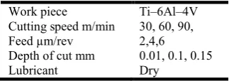
Table 6. Machining parameters and trail level
Work piece Ti–6Al–4V Cutting speed m/min 30, 60, 90, Feed µm/rev 2,4,6
Depth of cut mm 0.01, 0.1, 0.15 Lubricant Dry
and tolerance problems. Rigidity of the entire system is consequently very important, as is the use of sharp, properly shaped cutting tools. Characterization of surface topography is important in applications involving friction, lubrication, and wear (Thomas, 1999). In general, it has been found that friction increases with average roughness. Roughness parameters are, therefore, important in applications such as automobile brake linings, floor surfaces, and tires. The effect of roughness on lubrication has also been studied to determine its impact on issues regarding lubrication of sliding surfaces, compliant surfaces, and roller bearing fatigue. Finally, some researchers have found a correlation between initial roughness of sliding surfaces and their wear rate. Such correlations have been used to predict failure time of contact surfaces. Another area where surface roughness plays a critical role is contact resistance (Thomas, 1999). Thermal or electrical conduction
Contact Resistances Due to Constriction of Flow Lines (Thomas, 1999)
between two surfaces in contact occurs only through certain regions. In the case of thermal conduction, for example, the heat flow lines are squeezed together at the areas of contact, which results in a distortion of the isothermal lines, as illustrated in Figure 1.
RESULTS AND DISCUSSION
Thermal contact resistance is an important issue in space applications, such as satellites, where the heat generated by the electronic devices can only be driven away by conduction. Surface roughness is also a topic of interest in fluid dynamics (Thomas, 1999). The roughness of the interior surface of pipes affects flow parameters, such as the Reynolds number, which is used to evaluate the flow regime (i.e., laminar or turbulent). The performance of ships is also affected by roughness in the form of skin friction, which can account for 80-90% of the total flow resistance. In addition, the power consumption can increase as much as 40% during the service life of a ship as a result of increased surface roughness caused by paint cracking, hull corrosion and fouling. The examples
Table 1. Chemical composition of titanium alloy
Alloy Al V Fe C Ti
Ti-6Al-4V 6.40% 3.89% 0.16% 0.002% Balance
Table 2. Mechanical Properties of Ti-6Al-4V
Hardness (HRA) Hardness (HRA) Hardness (HRA) Hardness (HRA) Hardness (HRA) Hardness (HRA) Hardness (HRA)
70 363 950Mpa 14% 0.342 113Gpa 4.43g/cm3
Table 3. Typical physical properties for Ti6Al4V
Density g/cm3 (lb/ cu in) 4.42 (0.159)
Melting Range °C±15°C (°F) 1649 (3000)
Specific Heat J/kg.°C (BTU/lb/°F) 560 (0.134)
Volume Electrical Resistivity ohm.cm (ohm.in) 170 (67)
Thermal Conductivity W/m.K (BTU/ft.h.°F) 7.2 (67)
Mean Co Efficient of Thermal Expansion 0-100°C /°C (0-212°F /°F) 8.6x10⁻⁶ (4.8)
Mean Co-Efficient of Thermal Expansion 0-300°C /°C (0-572°F /°F) 9.2x10⁻⁶ (5.1)
Beta Transus °C±15°C (°F) 999 (1830)
Table 4. Tool specifications of CCGT09T301F Coated carbide insert
Composition 80% Al2O3 and 20% TiC
Grain Size 3.0 μm
Transverse Rupture Strength 551-786 MPa
Average density 3.90-3.99 g/cm3
Youngs Modulus 641 GPa
Hardness 91-94 HRA
[image:3.595.81.243.531.588.2]Fig. 1. Cutting forces vs. feed rate
[image:4.595.81.542.54.639.2]Fig. 2. Cutting forces vs. cutting speed
Fig. 3. Cutting forces vs. depth of cut
Fig. 4. Surface roughness vs. feed rate
surface roughness has to be carefully considered. However, the influence of roughness extends to various engineering concerns such as noise and vibration control, dimensional
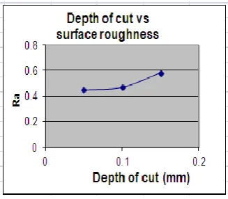
Fig.5. Depth of cut vs Surface roughness
[image:4.595.319.544.386.551.2]Fig.6. Cutting speed vs Surface roughness
Fig 7. Experimental setup
mentioned above are just a few of the applications in which
tolerance, abrasive processes, bioengineering, and
geomorphometry (Thomas, 1999).
[image:4.595.89.237.558.701.2]of cut there is a slight increase in surface roughness which indicates that depth of cut is not influencing as feed rate. Figure 7.
CONCLUSIONS
The following conclusions are based on the results of turning Ti-6Al-4V alloy with coated carbide tools under dry machining. Surface roughness values recorded when machining Ti-6Al-4V alloy under dry condition investigated were more affected by feed rate and also by nose radius. Three stages of trend line of surface roughness were high value at first machining followed by decreasing, Surface finish generated when machining Ti-6Al-4V alloy with coated carbide tools are generally acceptable and free of physical damage such as cracks and tears. Effects of machining on turned surface were micro pits, deformation of feed marks and red posited of titanium. The machined surface was found when cutting operation at cutting speed of 30, 60, and 90 m/min, feed rate of 0.02, 0.04, and 0.04 mm/rev and depth of cut of 0.01, 0.1, and 0.15mm and at the end of tool life. The lower surface roughness value produces the smoother surface topography and it has a strength correlation to the surface roughness.
REFERENCES
1. Benardos, P.G. and Vosniakos, G.C., 2002. Prediction of
surface roughness in CNC face milling using neural network and Taguchi’s design of experiments, Robotics and Computer Integrated Manufacturing, Volume 18, pp. 343-354.
2. Boothroyd, G. and Knight, W.A., 1989. Fundamental
Machining and Machine Tools 2nd edition, Marcel Dekker Inc.
3. Che Haron, C.H., 2001. Tool life and surface integrity in
turning titanium alloy, Journal of Materials Processing and Technology, Volume 118, pp. 231-237.
4. Che Haron, C.H., 2005. The effect of machining on
surface integrity of titanium alloy Ti-6Al-4V, Journal of Materials Processing and Technology, Volume 166, pp.188-192.
5. Ezugwu, E.O., 2007. Surface integrity of finished turned
Ti-6Al-4V alloy with PCD tools using conventional and high coolant supplies, International Journal of Machine Tools & Manufacture, Volume 47, pp. 884-891.
6. Ezugwu E.O., Bonney J. and Yamane Y., 2003. An
Overview of The Machinability of Aeroengine alloys, Journal of Material Processing and Technology, Volume 134, pp. 233-253.
7. Field and Kahles, 1971. Review of surface integrity of machined components, Ann. CRIP 20, Volume 2, pp. 153-163.
8. Kalpakjian, S. and Rchmid, S.R., 2001. Manufacturing Engineering and Technology International Edition, Prentice Hall 2001.
9. Kennametal, 2006. Kennametal Lathe Tooling
Catalogue, Kennametal Company.
10. Thomas, T.R., “Trends in surface roughness”,
International Journal of Machine Tools and Manufacture, 38, Issues 5-6, pp 405-411 (1998).
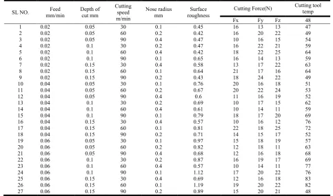
Experimental observations
SL NO. Feed
mm/min
Depth of cut mm
Cutting speed m/min
Nose radius mm
Surface roughness
Cutting Force(N) Cutting tool
temp
Fx Fy Fz 48
1 0.02 0.05 30 0.1 0.45 16 13 13 47
2 0.02 0.05 60 0.2 0.42 16 20 22 49
3 0.02 0.05 90 0.4 0.47 10 16 15 54
4 0.02 0.1 30 0.2 0.47 16 22 21 59
5 0.02 0.1 60 0.4 0.42 18 22 25 64
6 0.02 0.1 90 0.1 0.65 16 14 13 59
7 0.02 0.15 30 0.4 0.58 13 17 22 63
8 0.02 0.15 60 0.1 0.64 21 17 16 64
9 0.02 0.15 90 0.2 0.43 18 24 22 49
10 0.04 0.05 30 0.1 0.76 20 16 18 51
11 0.04 0.05 60 0.2 0.67 20 22 24 53
12 0.04 0.05 90 0.4 0.6 11 16 19 52
13 0.04 0.1 30 0.2 0.69 10 17 15 62
14 0.04 0.1 60 0.4 0.61 10 14 11 59
15 0.04 0.1 90 0.1 0.79 18 17 20 69
16 0.04 0.15 30 0.4 0.57 10 16 12 76
17 0.04 0.15 60 0.1 0.81 22 18 25 72
18 0.04 0.15 90 0.2 0.71 14 15 17 52
19 0.06 0.05 30 0.1 0.97 15 18 19 57
20 0.06 0.05 60 0.2 0.82 12 18 11 63
21 0.06 0.05 90 0.4 0.68 12 16 18 68
22 0.06 0.1 30 0.2 0.87 16 19 17 69
23 0.06 0.1 60 0.4 0.57 10 14 11 77
24 0.06 0.1 90 0.1 1.12 17 20 22 76
25 0.06 0.15 30 0.4 0.69 12 16 18 83
26 0.06 0.15 60 0.1 1.19 19 20 22 82
27 0.06 0.15 90 0.2 0.89 15 20 21 48