© 2019, IRJET | Impact Factor value: 7.211 | ISO 9001:2008 Certified Journal | Page 2173
An Analytical study on Application of Virtual Outrigger in Tall
Buildings to Reduce Disproportionate Collapse and Increase Efficiency
Anne Jacob
1, Aswini J
21
P.G Student, Dept. of Civil Engineering, SCMS School of Engineering and Technology, Karukutty, Ernakulum
Kerala, India
2
Assistant Professor, Dept. of Civil Engineering, SCMS School of Engineering and Technology, Karukutty,
Ernakulum Kerala, India
---***---Abstract -
Virtual outriggers are an up gradation ofconventional outrigger and belt truss system. Outriggers are systems which resist lateral load. It consist of stiff arms connecting core and outer columns, when engaged in tall slender buildings resist bending of the core and hence reduce overturning moment and maximum lateral deflection of free core. Virtual outriggers are advantageous compared to conventional outriggers because they save space and prevent complicated connections.
In this paper an 80-storey RCC building frame is studied and conventional outriggers are first modeled and the optimum positions are fixed based on least lateral deflection of the building model. The study is carried out in ETABS 2016. From the gap identified in literature review, a four outrigger system was modeled. Virtual outriggers are then employed in the model building. Response spectrum analysis was done and maximum lateral displacement, storey drifts of model were compared for distinct variations of virtual outrigger systems. The effect of various configurations of belt truss is studied. Effect of virtual outriggers on progressive collapse is also done. For the 3-D model about 31% reduction in maximum displacement and 34% reduction in storey drifts are achieved with optimum location of the virtual outrigger and x bracing are found to be most effective configuration for belt truss. Virtual outriggers act as an effective method in controlling progressive collapse by distributing the extra gravity loads equally.
Key Words: Bracings, Outrigger and belt truss, progressive collapse, Response spectrum analysis, Virtual outrigger
1. INTRODUCTION
Outrigger and belt system is a productive and economical system which resists lateral load that is administered on tall slender buildings. Outrigger member is a stiff beam or truss tying core to outrigger columns which refrains the core from rotation under effects of lateral loading and the belt member connects all the outer columns together to distribute the load equally and lessen the differential lengthening and shrinking of perimeter columns. Belt can be a truss or beam. This system reduces parameters like maximum lateral deflection, storey drifts and core moment and improves the strength and overturning stiffness of buildings. Outrigger and belt truss/wall extends to a minimal depth of one storey and this result in uninhabitable floors which poses as a
hindrance to efficiency of conventional outrigger. Virtual outrigger is an upgraded version of conventional outrigger. It consists of only a belt member. All the functions done by outrigger member in conventional outrigger systems are done by tough and firm floor members or slabs at the level of outrigger. The moment in the core gets conveyed to the belt truss as plain couples and is transmitted to foundation as vertical forces through belt member. The slab gets stressed severely and hence slabs thicker than normal are required and should be gauged and reinforced accordingly. Even though the efficiency of the virtual outrigger is lesser compared to conventional outrigger it is negligible due to the advantages of virtual outrigger system in building. Several other improvisations were made to conventional outrigger before virtual outrigger like offset outriggers and diagonal outriggers. In offset outriggers the outrigger member are kept at a distance away from core and hence direct connection to core is not required. In diagonal outriggers the outrigger trusses are diagonally connected. The factors affecting the efficacy of outrigger system are the stiffness and location of the outrigger and belt truss system, the size and shape of building, floor-to- floor height of the building, and the core etc.
2. METHODOLOGY AND MODELLING
2.1 Software Study
ETABS is an engineering software product that is commonly used to analyze and design multi-story building. This paper focuses on analyzing an 80 storey R.C.C building model for outcome of lateral loads -wind and earthquake loads. Loads considered are taken with reference to IS-875(Part 3), IS 1893(2002) code. The steps involved are;
1. Set stories and grid system 2. Define material properties
3. Define section properties like frame and slab sections 4. Draw beam, column, slab and wall sections
5. Define load cases and load combinations
6. Assign all loads- dead and live loads on structural members
© 2019, IRJET | Impact Factor value: 7.211 | ISO 9001:2008 Certified Journal | Page 2174
8. Define response spectrum and time history functions9. Define mass source and assign diaphragms 10. Define load cases and model cases
11. Run analysis for load cases and combinations
12. Obtain displacement and drift from storey response plots
13. Model virtual outrigger and run the analysis
14. Obtain results for distinct variations of virtual outrigger
15. Model varying belt truss configurations and compare the results
16. Study the effect on progressive collpse
2.2 Details of model
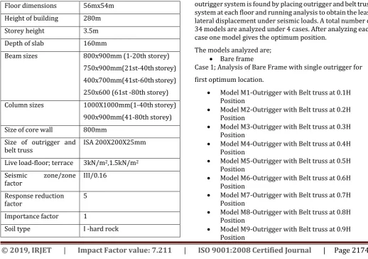
[image:2.595.318.550.187.391.2]The details of the model used for study are shown in table 1. Table gives structural details as well as details for seismic and wind analysis. In this study, an 80-storey structure of a commercial building has been analyzed by using ETABS software. The plan selected is rectangular in shape. It is an architectural plan and not an existing or proposed building. The structure is analyzed for static and dynamic wind and earthquake force.
Table -1: Details of Model Floor dimensions 56mx54m Height of building 280m
Storey height 3.5m
Depth of slab 160mm
Beam sizes 800x900mm (1-20th storey) 750x900mm(21st-40th storey) 400x700mm(41st-60th storey) 250x600 (61st -80th storey) Column sizes 1000X1000mm(1-40th storey)
900x900mm(41-80th storey) Size of core wall 800mm
Size of outrigger and
belt truss ISA 200X200X25mm
Live load-floor; terrace 3kN/m2,1.5kN/m2 Seismic zone/zone
factor III/0.16
Response reduction
factor 5
Importance factor 1
Soil type I -hard rock
Terrain category IV
Wind speed 50m/s
The plan of the model is shown in figure 1. The building has two lifts at the centre. There are four ducts provided nearby the lifts.
Fig -1: Plan of model
Bare frame is analyzed first. The optimum position of four outrigger system is found by placing outrigger and belt truss system at each floor and running analysis to obtain the least lateral displacement under seismic loads. A total number of 34 models are analyzed under 4 cases. After analyzing each case one model gives the optimum position.
The models analyzed are; Bare frame
Case 1;Analysis of Bare Frame with single outrigger for first optimum location.
Model M1-Outrigger with Belt truss at 0.1H Position
Model M2-Outrigger with Belt truss at 0.2H Position
Model M3-Outrigger with Belt truss at 0.3H Position
Model M4-Outrigger with Belt truss at 0.4H Position
Model M5-Outrigger with Belt truss at 0.5H Position
Model M6-Outrigger with Belt truss at 0.6H Position
Model M7-Outrigger with Belt truss at 0.7H Position
Model M8-Outrigger with Belt truss at 0.8H Position
[image:2.595.34.553.435.799.2]© 2019, IRJET | Impact Factor value: 7.211 | ISO 9001:2008 Certified Journal | Page 2175
Model M10-Outrigger with Belt truss at 1.0HPosition
Case 2: Analysis of Bare Frame with double outrigger system for Second position keeping first position common at 0.6H
Model M11-Outrigger with Belt truss at 0.1H Position
Model M12-Outrigger with Belt truss at 0.2H Position
Model M13-Outrigger with Belt truss at 0.3H Position
Model M14-Outrigger with Belt truss at 0.4H Position
Model M15-Outrigger with Belt truss at 0.5H Position
Model M16-Outrigger with Belt truss at 0.7H Position
Model M17-Outrigger with Belt truss at 0.8H Position
Model M18-Outrigger with Belt truss at 0.9H Position
Model M19-Outrigger with Belt truss at 1.0H Position
Case 3: Analysis of Bare Frame with three outrigger system for third position keeping first position common at 0.6H and second at 0.2H
Model M20-Outrigger with Belt truss at 0.1H Position
Model M21-Outrigger with Belt truss at 0.3H Position
Model M22-Outrigger with Belt truss at 0.4H Position
Model M23-Outrigger with Belt truss at 0.5H Position
Model M24-Outrigger with Belt truss at 0.7H Position
Model M25-Outrigger with Belt truss at 0.8H Position
Model M26-Outrigger with Belt truss at 0.9H Position
Model M27-Outrigger with Belt truss at 1.0H Position
Case 3: Analysis of Bare Frame with four outrigger system for fourth position keeping first position common at 0.6H , second at 0.2H and third at 0.8H
Model M28-Outrigger with Belt truss at 0.1H Position
Model M29-Outrigger with Belt truss at 0.3H Position
Model M30-Outrigger with Belt truss at 0.4H Position
Model M31-Outrigger with Belt truss at 0.5H Position
Model M32-Outrigger with Belt truss at 0.7H Position
Model M33-Outrigger with Belt truss at 0.9H Position
Model M34-Outrigger with Belt truss at 1.0H Position
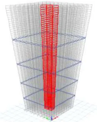
Fig -2: Structural model with outrigger and belt truss
3. VIRTUAL OUTRIGGER
Virtual outriggers are modified conventional outriggers. The advantages of virtual outriggers are vast that they are widely deployed. Floor space is saved in virtual outrigger which is occupied by outrigger member in conventional system. The complicated connection between outrigger and core is avoided and outrigger columns can be placed as per architectural and functional requirements. The conventional outrigger is modified to virtual outrigger by taking out the outrigger members and leaving only belt member. The virtual outrigger model is shown in figure 3. The core is not directly connected to the outrigger columns instead the floor members are used to transfer the moment from the core to the outer columns.
[image:3.595.325.538.168.323.2] [image:3.595.331.487.545.741.2]
© 2019, IRJET | Impact Factor value: 7.211 | ISO 9001:2008 Certified Journal | Page 2176
3.1 Determination of Optimum Position
[image:4.595.343.527.121.251.2]The analysis results of models are shown in table 2 to table 5. The optimum position of single outrigger system is obtained from analysis of case 1. The results from table 2 show that M6 which is model with outrigger and belt truss system at 48th storey gives the least displacement. The lateral displacement reduces by 20% with single outrigger system. Hence 48th storey is the optimum position of single outrigger system. In table 3 results of case 2 models are shown and model M12 gives the least displacement. Lateral displacement reduced by 31% with double outrigger system. Hence optimum position of second outrigger is at 16th storey with first outrigger at 48th storey.
Table -2: Displacement of Models in Case 1
Model Displacement (mm) BARE FRAME 219
M1- 8th storey 192 M2-16th storey 191 M3-24th storey 189 M4-32nd storey 187 M5-40th storey 184 M6-48th storey 175 M7-54nd storey 179 M8-64th storey 181 M9-72nd storey 191 M10-80th storey 192
[image:4.595.72.252.300.479.2]Table 4 shows the case 3 models and model M25 gives the least displacement. The lateral displacement reduces by 36% with three outrigger system. Hence optimum position of third outrigger is 64thstorey.
Table -3: Displacement of Models in Case 2
Model Displacement (mm) M11- 8th storey 173
M12-16th storey 151 M13-24th storey 152 M14-32nd storey 154 M15-40th storey 159 M16-54nd storey 164 M17-64th storey 166 M18-72nd storey 167 M19-80th storey 168
Table -4: Displacement of Models in Case 3
Model Displacement (mm) M20- 8th storey 154
M21-24th storey 153 M22-32nd storey 152 M23-40th storey 150 M24-54nd storey 149 M25-64th storey 140 M26-72nd storey 152 M27-80th storey 153
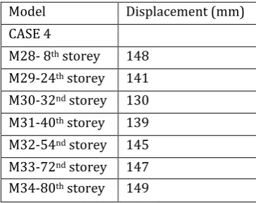
[image:4.595.342.524.343.487.2]Table 5 shows the case 4 models and model M30 gives the least displacement. Hence the optimum position of fourth outrigger is 32nd storey. The lateral displacement reduces by 41% with four conventional outrigger systems.
Table -5: Displacement of Models in Case 4
Model Displacement (mm) CASE 4
M28- 8th storey 148 M29-24th storey 141 M30-32nd storey 130 M31-40th storey 139 M32-54nd storey 145 M33-72nd storey 147 M34-80th storey 149
The optimum position of four outrigger and belt truss system are obtained at 48th, 16th , 64th , 32nd storey respectively. The displacement of model is seen to reduce from 219mm to 130mm in model with four outrigger systems.
4. RESULTS AND DISCUSSIONS
4.1 Lateral Displacement
Lateral displacement can be defined as the total displacement of ith storey with respect to ground level and there is maximum permissible limit prescribed in IS codes. Lateral loads have a greater effect on taller buildings and hence should be studied thoroughly.
[image:4.595.72.249.570.737.2]© 2019, IRJET | Impact Factor value: 7.211 | ISO 9001:2008 Certified Journal | Page 2177
system even though there is no change in slab thickness inthe virtual outrigger model.
Chart -1: Comparison of lateral displacement
In chart 2 the graph shows virtual outrigger models with varying depth of slab at the level of outrigger.
When the thickness of slab increases the lateral displacement decreases. When slab thickness is increased from 160mm to 200mm the result obtained is comparable with conventional outrigger system. At 200mm deep slab the lateral displacement reduces to 154mm. Increasing slab depth can further reduce the displacement but may pose economical issues. The variation in the lateral displacement is neglected considering the advantages of virtual outrigger.
Chart -2: Lateral displacement of virtual models with varying slab thickness
Chart 3 shows the virtual outrigger model with varying depth. Depth is increased from one storey to three storeys deep. The graph shows that as depth of belt truss increase the displacement reduces and is almost comparable with conventional outrigger system. Since the outrigger members
are absent the system stays economical even for increased depths. Sometimes the slab thickness are increased by 10 folds.
Chart -2: Lateral displacement of virtual models with varying storey deep
The displacement reduces from 175mm to 151mm for three storey deep belt trusses. Even if the values of lateral displacement of conventional and virtual vary it is neglected because of its advantages over conventional system.
4.2 Storey Drifts
Storey drift is the drift of one level of a multistory building relative to the level below. Interstorey drift is the difference between the roof and floor displacements of any given storey as the building sways during the earthquake.
[image:5.595.42.279.135.302.2]Storey drifts of bare frame, conventional outrigger and virtual outrigger with varying depth and slab thickness is compared in table 6.
Table -6: Storey Drift of Types of Outrigger System
Models Max. Storey drifts % reduction
Bare Frame 0.001361 --
Conventional
outrigger 0.000849 37%
Virtual
outrigger 0.001105 18%
Virtual with 200mm deep slab
0.000945 31%
Virtual with
3-storey deep 0.000901 34%
© 2019, IRJET | Impact Factor value: 7.211 | ISO 9001:2008 Certified Journal | Page 2178
with conventional outrigger system the drift gets reduced by37%. As virtual outrigger with no change is used the reduction is only 18% but still gives lesser value than bare frame.
When virtual outrigger is with 200mm deep slab and is 3-storey deep, the reduction in 3-storey drift is by 31% and 34% and is comparable with conventional system. Hence in summary outrigger reduces the storey drift.
5. STUDY ON VARYING CONFIGURATIONS OF BELT
TRUSS
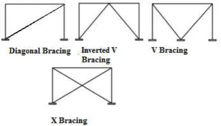
Different configurations are used for belt truss member. The type of configurations affects the efficiency of the building which is represented by lateral displacement and the storey drifts. The type of configurations include diagonal bracing, double diagonal or x bracing, k or v bracing, inverted v bracing. Figure 4 shows the various configurations.
Fig -4: Various configurations of belt truss used in the study
[image:6.595.41.269.341.471.2]Conclusions are made based on lateral displacement and storey drifts. Table 7 shows that lateral displacement and storey drift is least for x bracing. Hence it can be suggested to use double bracing system in tall buildings to improve the lateral stiffness against lateral loads. This validates use of X bracing in the project model.
Table -7: Lateral displacement of model with varying belt truss configurations
Bracing type Lateral displacement (mm)
Storey Drifts
Bare frame 219 0.001361
X bracing 175 0.001073
V bracing 192 0.001342
Inverted V bracing
193 0.001242
Diagonal bracing 202 0.001211
6. PROGRESSIVE COLLAPSE
Progressive collapse can be simply described as the partial or whole collapse of an entire building due to loss of a load carrying member, the column, due to natural or manmade hazards. Buildings that are tall are susceptible to progressive collapse. Buildings with lateral load resisting systems are found to resist or prevent progressive collapse. The load from the effect of removing a column is distributed among all other columns equally by the help of belt truss and hence helps in providing an alternate load path for the gravity load developed. Linear static analysis is done in ETABS software and at the bay where column is removed the structure is subjected to a load combination of 2(DL +0.25LL). Demand- Capacity ratio or DCR of columns is calculated from the software and is checked with acceptance criteria for progressive collapse. If DCR>1.5 (for atypical configurations) then column fails and progressive collapse is initiated.
Table -8: DCR values of columns affected due to column removal in bare frame
Building Conditions
Case No
Column Removed
Columns affected
DCR values
Bareframe Case 1
C1(first floor)
C2(first floor)
1.817
C2(ground) 1.848
C3 (second floor)
1.804
Case 2
C101(First floor)
C51 (Ground)
1.089
C5(Ground) 1.017
Case3 C7(First floor)
C1( Ground)
1.821
C6 (Ground)
1.8
C8 (Ground)
[image:6.595.90.563.357.793.2]© 2019, IRJET | Impact Factor value: 7.211 | ISO 9001:2008 Certified Journal | Page 2179
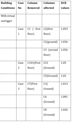
Table -9: DCR values of columns affected due to columnremoval in model with virtual outrigger
Building Conditions
Case No
Column Removed
Columns affected
DCR values
With virtual outrigger
Case 1
C1 ( first floor)
C2(first floor)
1.053
C2(ground) 1.036
C3 (second floor)
1.056
Case 2
C101(First floor)
C51 (Ground)
1.05
C5(Ground) 1.02
Case 3
C7(First floor)
C1( Ground)
1.013
C6 (Ground)
1.001
C8 (Ground)
1.026
Bare frame and model with virtual outrigger is analyzed for three cases of column removal. In case 1 a corner column on floor above ground is removed. In case 2 a column at middle along shorter direction is removed and in case 3 an inner column is removed. All three cases are analyzed and the table 8 and table 9 give the results.
The table shows that building without virtual outrigger system undergoes progressive collapse since DCR ratio exceeds 1.5 while the model with virtual outrigger remains intact even after removal of columns with DCR ratio less than 1.5.
7. CONCLUSIONS
The conventional outrigger system reduced to virtual outrigger system with only belt truss around the building and no outrigger truss connecting core and perimeter columns is analyzed in this study. The study can be concluded as below.
The virtual outrigger system is analyzed for response spectrum. The virtual outrigger with no changes showed 25% higher displacement than conventional outrigger system but showed 10% lesser displacement than bare frame.
Virtual outrigger was also modified by increasing the depth of the belt truss from single storey deep to two storeys deep and to three storeys deep and the variation in displacement was determined to vary from 175 to 151 mm.
Virtual outrigger was then modified by increasing the slab thickness of the floor at the outrigger level from 160mm to 200mm and the displacement for each was determined to vary from 175 to 154 mm. Storey drifts for the building model was also determined from storey response curve. Storey drifts reduced from 0.001361 for bare frame to 0.000814 for model with four outriggers and increased to 0.001105 when outrigger arms were removed.
Storey drift reduced to 0.000945 and to 0.000901 for virtual outrigger model with 200mm deep slab and 3 storey deep belt truss.
Storey drift reduced by 37% when conventional outrigger system was introduced in the model. When virtual outrigger with 200mm deep slab was
employed, the drift reduced by 31% when compared with bare frame
When virtual outrigger belt truss 3-storey deep was employed, the drift reduced by 34% when compared with bare frame
Study on configuration of belt truss gives following results
X bracing is more economical since it has less structural weight
X bracing is more efficient since it gives least displacement and least storey drift.
© 2019, IRJET | Impact Factor value: 7.211 | ISO 9001:2008 Certified Journal | Page 2180
ACKNOWLEDGEMENT
The authors acknowledge the kindness and co-operation of the coordinators and local administrators in the study area, and the support of the Department of Civil Engineering, Kerala Technical University
REFERENCES
[1] Iqra A.khan and N G Gore, “Study of Different Aspects of Outrigger Structural System: A Review”, International Journal of Innovative Research in Science, Engineering and Technology, Vol. 7, Issue 3, March 2018.
[2] Minu Mathew and Manjusha Mathew, “Optimum Position of Outrigger with Belt Wall”, International Journal of Innovative Research in Science, Engineering and Technology, Vol. 6, Issue 6, June 2017.
[3] Alok Rathore and Dr. Savitha Maru, “Dynamic Analysis of Outrigger Structural System In Tall Building, International Journal of Modern trends in Engineering and Research, Vol. 04, Issue 12, December 2017.
[4] Rob Smith “The Damped Outrigger - Design and Implementation”, International Journal of High-Rise Buildings, March 2016, Vol. 5, No 1, 63-70
[5] Vasudev M.V and Vinay Pai S.,” Performance Study for Optimum Location of Multi-Outrigger and Belt Truss System in Tall Structures”, International Journal for Scientific Research & Development, Vol. 4, Issue 07, 2016.
[6] R. Kamgar and R Rahgozar, “Determination of Optimum Location For Flexible Outrigger Systems In Non-Uniform Tall Buildings Using Energy Method”, International Journal Of Optimization In Civil Engineering, 2015; Vol. 5(4):433-444
[7] Richard J. Balling and Jacob S Lee, “Simplified Model for Analysis and Optimization of Skyscrapers with Outrigger and Belt Trusses”, ASCE Journal of Structural Engineering, 2015, 141(9): 04014231
[8] Fouad R. Moudarres “Outrigger-Braced Coupled Shear Walls”, ASCE Journal of Structural Engineering. 1984, 110(12): 2876-2890
[9] Ali SherifS. Rizk, “Structural Design Of Reinforced Concrete Tall Buildings”, CTBHU Journal, Issue 1, pp. 43-4, 2010
[10] Karan D.Sitapara and N.G. Gore, “Review On Feasibility Of High Rise Outrigger Structural System In Seismically
Active Regions” International Research Journal of Engineering and Technology,Vol. 03 Issue 07,pp.197-203, 2016
[11] Gadkari A. P, Gore N. G, “Review on Behaviour of Outrigger Structural System in High-Rise Building”, International Journal of Engineering Development and Research (IJEDR),Vol. 4 Issue 2, July – 2016
[12] Sitapara K. D,Gore N. G, “Review on Feasibility of High Rise Outrigger Structural System in Seismically Active Regions”, International Research Journal of Engineering and Technology (IRJET), Volume: 03,Issue: 05,May-2016
[13] Mulla A. K, Srinivas B. N, “A Study on Outrigger System in a Tall R.C Structure with Steel Bracing”, International Journal of Engineering Research & Technology (IJERT), 2015