Camera Self-Calibration for the ARToolKit
J. Abdullah and K. Martinez
Intelligence, Agents and Multimedia, University of Southampton
[email protected], [email protected]
Abstract
Camera calibration is an essential and important part of an Augmented Reality (AR) system. The use of a plane-based calibration technique can give a good accuracy, which can be important for AR applications. The calibration technique used in the current ARToolKit requires user intervention, which is prone to error and involves a lengthy calibration time. The camera has to be recalibrated every time the focal length changes which is cumbersome and less suitable for applications where a more automated and easier approach is needed. This paper investigates the use of camera self-calibration for the ARToolKit, which has the advantage of simplicity of implementation. In order to improve its accuracy, a distortion model is also investigated. In this context several interesting results are presented.
1. Introduction
1.1 Augmented Reality
Augmented Reality (AR) is actually overlaying 3D virtual objects on the real world in real time. AR enhances the user's view of the real world with visual information from the computer. According to [8], AR is a system that has the following three characteristics:
1) Combines real and virtual 2) Interactive in real time 3) Registered in 3-D
Therefore, overlaying 2D virtual objects on the real world could not be considered AR. Films like "Jurassic Park" also could not be regarded as AR since they are not interactive media.
Camera calibration is one of the important tasks in AR systems. It establishes the projection from the 3D world co-ordinates to the 2D image co-ordinates. This can be achieved by finding the intrinsic and extrinsic camera parameters. Once the parameters are determined, 3D information can be inferred from 2D information, and vice versa.
Regardless of the specific application, existing camera calibration techniques can be classified into two [9] techniques. This classification divides camera calibration
into situations with known scenes and unknown scenes. Normally, for known scenes a planar pattern is used to find the camera parameters whereas for unknown scenes, camera motion is used. For the case where neither the scene nor the camera motion is known, it requires self-calibration.
The most likely problem faced in AR applications is the registration problem [8]. The virtual object must be properly aligned with the real world. There are two types of error source that can cause registration problems: static and dynamic [10]. Static errors are the ones that cause registration errors when both the user's viewpoint and the object in the environment remains still. Dynamic errors are the ones that cause registration errors when either the viewpoint or the objects begin to move.
One way to minimize the registration errors is by having a robust camera calibration. In order to achieve this, certain criteria must be met. Tsai [1] stated that the calibration procedure should be an autonomous process, meeting certain accuracy requirements, reasonably efficient and versatile. Therefore, any work to develop more robust calibration techniques should have at least the aforementioned criteria in mind.
1.2 The ARToolKit
The ARToolKit (Augmented Reality ToolKit) is a software useful in creating AR applications. Three types of AR display that can be used with the ARToolKit including monitor based, video see-through and optical see-through displays. Different kinds of displays require different kinds of calibration routines. The calibration procedure in the ARToolKit can be categorised as semi-automatic calibration since it involves users intervention as well as the computer.
especially when the focal length changes either intentionally or not.
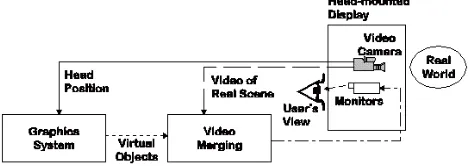
[image:2.612.60.295.202.285.2]In this paper, we propose a self-calibration technique for the camera in a monitor-based AR display for the ARToolKit. Our aim is to find parameters in the 3x3 calibration matrix. Once these parameters are determined, they can be used to calculate the transformation matrix, which is important to make sure the virtual object is overlaid accurately.
Figure 1: Monitor-based AR display
2. Background theory
2.1 Calibration matrix
We consider the pinhole model for the camera model. The camera is described by the following 3x3 upper triangular matrix:
=
1 0 0
0 0
0
v u r
v u
α α
Κ , (1)
where αu and αv are the horizontal and vertical scale factors respectively, r is the degree of slant between the horizontal and vertical image axes, and (u0,v0) is the principal point of the image. In this paper, we use a reduced set of intrinsic parameters. We will assume that
0 =
r which means that the image axes are orthogonal which is almost true in practice.
2.2 Camera Model
The transformation from 3D world co-ordinates to camera pixel co-ordinates can be modelled as a process of four steps [1, 2, 4]:
Step 1:
Rigid body transformation from the object world coordinate system (Xw,Yw,Zw)to the camera 3D coordinate system(X,Y,Z):
[
]
=R[
]
T +tw w w
T X Y Z
Z Y
X (2)
Step 2:
Transformation from 3D camera coordinates (X,Y,Z)to ideal (undistorted) image coordinates (x,y)using perspective projection with pinhole camera geometry:
, Z X f x=
Z Y f
y= , (3)
where f is the effective focal length Step 3:
Lens distortion:
x x
x= ˆ+δ , y= yˆ+δy, (4) where )(xˆ,yˆ are the distorted or true image coordinates on the image plane, and (δx,δy)are the distortion corrections to (x,y). The value for δxand δywill be discussed later.
Step 4:
Affine transformation from real image coordinates (xˆ,yˆ) to frame buffer (pixel) image coordinate(u,v):
0 1xˆ u
d
u= x− + ,
0 1yˆ v
d
v= y− + , (5) where )(u0,v0 are the coordinates of the image centre (the principal point) in the frame buffer, dxand dy are the distance between adjacent pixels in the horizontal and vertical directions of the image plane, respectively. Lens distortion mainly comprises two components: radial and decentering. Radial distortion is caused by imperfect lens shape and decentering is usually caused by improper lens assembly. The distortion corrections (δxandδy) are expressed as power series in radial distancer:
) (
ˆ 6
3 4 2 2
1 + + +L
=x kr k r k r x
δ
+[p1(r2+2xˆ2)+2p2xˆyˆ](1+p3r2+L) (6) )
(
ˆ 6
3 4 2 2
1 + + +L
=y k r k r k r
y
δ
where r = xˆ2+yˆ2 , k1, k2and k3are coefficients of radial distortion, andp1, p2and p3are coefficients of decentering distortion.
In order to keep the algorithm simpler for the ARToolKit, we only include radial distortion. According to [1], unless one is specifically concerned with the reduction of distortion to very low levels, it is likely that the distortion function is totally dominated by the radial components, and especially dominated by the k1 term.
2.3 Epipolar Geometry
Epipolar geometry can be described by a 3x3 matrix called the fundamental matrix and it has the following expression
1
− −
≅K S(t)RK
F T (8)
where Rand trepresent the relative rotation and translation between the two camera positions, S(t) is the skew-symmetric matrix associated with three-vector t. ≅
stands for equality up to a scale factor. 2.4 Fundamental Matrix Estimation
The fundamental matrix can be robustly estimated from point matches given at least seven point-to-point correspondence. If a point mi =
[
ui vi]
T in the first image is matched to a point m′i =[
ui′ vi′]
Tin the second image, they must satisfy the following epipolar equation:0 ~ ~′ =
i T i Fm
m (9)
In this paper we use publicly available software "image matching" [12] to get the accurate determination of point correspondence and to estimate the fundamental matrix.
3. Self Calibration
There are several techniques reported in the literature for self-calibration [6, 7]. These techniques are all rely on known motions of the cameras. In [7] the motion of the camera is assumed to be translational, while in [6] rotational motions of the camera are considered, but rotation must be through known angles.
The method chosen here is the algebraic Dornaika’s method [5]. This method is used because it outperforms the Kruppa equations in terms of convergence and accuracy and also for its simpler algorithm, which is more suitable for the ARToolKit.
The method is derived from equation (8). The equation can be rewritten as
S(t) FKR
KT T ≅ . (10)
Let alj,1≤l,j≤3 be entries of KTFKRT. From this it follows that
0
32 23 31 13 21 12 33 22
11=a =a =a +a =a +a =a +a =
a
(11) The rotation Ris represented by its associated unit
quaternion T
z y x q q q
q , , , ) ( 0
=
q . More details of the
derivation of the method can be found in [5].
For n fundamental matrix, we accumulate the constraints (11) by building a positive error function f that will be minimized over the unknown. The error function can have the following form:
] ) 1 ( )
, , , , , ,
( 2 2
2
1
1 i
n
i i n
o o v u u v
f q q =
∑
v + − q=
λ α
α K
(12) where (a ,a ,a ,a a ,a a ,a a )T
32 23 31 13 21 12 33 22
11 + + +
=
v ,
and λis a real positive number. 3.1 Distortion
There are two ways of dealing with distortion. As a start we are concerned with the radial distortion. Often in literature, the fundamental matrix is estimated based on the assumption that distortion in the captured image is corrected offline. However, there is a paper reported by Zhang [4], which integrates the distortion correction when estimating the epipolar geometry. In this context we only concentrate on the former method for its simplicity.
4. Experiment
An experiment was conducted in order to check the accuracy of the intrinsic parameters from the camera self-calibration routine. The results are compared with the one from the ARToolKit. In the experiments carried out to test the self-calibration algorithm, image sequences, rather than individual image were used.
K is initialized using reasonable figures quoted by camera the manufacturer or from educated guess. The quaternion
1. The camera that needs to be calibrated should capture at least 3 images by moving the camera. 2. Find the point correspondence between each pair
of images based on relaxation and correlation techniques.
3. From the point correspondence, the fundamental matrix is estimated. Each pair will produce one fundamental matrix.
4. The essential matrix would then be estimated based on this relation Ei ≅KTFiK.
5. Based on the essential matrix, each quaternion qi is estimated by factorizing the corresponding essential matrix as Ei≅S(ti)R(qi).
The initial intrinsic parameters together with the obtained quaternions constitute the starting point of the nonlinear equation in (12). The calibration matrix from self-calibration and ARToolKit is presented as follows:
0 50 100 150 200 250 300 350 400 450 500 0
50 100 150 200 250 300 350 400 450 500
Horizontal axis Ve
rtic al a xi s
[image:4.612.336.520.253.390.2]ARToolKit Self-Calibration
Figure 2: Principal Point without distortion correction.
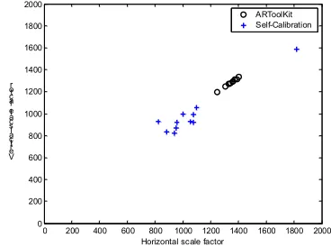
0 200 400 600 800 1000 1200 1400 1600 1800 2000 0
200 400 600 800 1000 1200 1400 1600 1800 2000
Horizontal scale factor Ver
tic al s cale f acto r
ARToolKit Self-Calibration
Figure 3: Scale Factor without distortion correction.
0 50 100 150 200 250 300 350 400 450 500 0
50 100 150 200 250 300 350 400 450 500
Horizontal axis V
erti cal a xis
ARToolKit Self-Calibration
Figure 4: Principal point after distortion correction
0 200 400 600 800 1000 1200 1400 1600 1800 2000 0
200 400 600 800 1000 1200 1400 1600 1800 2000
Horizontal scale factor Ver
ti cal sc ale f acto r
ARToolKit Self-Calibration
Figure 5: Scale factor after distortion correction
From these results, we can observe that the principal point estimation for self-calibration without distortion correction is quite reliable. However Figure 4 and Figure 5 show improvements in the clusters for the self-calibration method in comparison to clusters in Figure 2
and Figure 3. From here we can presume that by taking distortion into account will improve the accuracy of the camera parameters.
5. Conclusion and Future Work
Although the algorithm proposed here is not as robust as the existing algorithm in the ARToolKit, but this could be considered as a first step towards a more automatic calibration process without the needs for a particular pattern. Improvement can be made by accurately estimating the fundamental matrix which is largely related to the accuracy of point correspondence matching. Once this is achieved, it is easier to obtain a good estimation of the camera parameters.
6. References
[1] R. Tsai, “A versatile camera calibration technique for high-accuracy 3D machine vision metrology using off-the-shelf TV cameras and lenses”, IEEE Journal of Robotics and Automation, August 1987, pp.323-344.
[2] D.C. Brown, “Close-range camera calibration”,
Photogrammetric Engineering, 1971, pp. 855-866.
[3] C. C. Slama, “Manual of Photogrammetry”, American
Society of Photogrammetry, 1980.
[4] Zhengyou Zhang, “On the epipolar geometry between two images with lens distortion”, InProceeding of the International.
Conference on Pattern Recognition, Vienna, August 1996, pp.
407-411.
[5] F. Dornaika and R. Chung, “An Algebraic Approach to Camera Self-Calibration”, Computer Vision and Image
Understanding, 2001, pp.195-215
[6] Anup Basu, “Active calibration: Alternative strategy and analysis”, In Proceeding of the IEEE Conference on Computer
Vision and Pattern Recognition, 1993, pp. 495-500.
[7] Lisa Dron, “Dynamic camera self-calibration from controlled motion sequences”, In Proceeding of the IEEE Conference on
Computer Vision and Pattern Recognition, 1993, pp. 501-506,.
[8] R.T. Azuma, “A survey of augmented reality”, Presence:
Teleoperators and virtual environments, 1997, vol. 6, no. 4, pp.
355-385,.
[9] Milan Sonka, Vaclav Hlavac, Roger Boyle, Image
Processing, Analysis, and Machine Vision, 2nd Edition, PWS
Publishing, 1999.
[10] Holloway, Richard, “Registration Errors in Augmented Reality”, Ph.D dissertation. UNC Chapel Hill Department of Computer Science technical report TR95-016, August 1995.