Abstract—In this paper the simulation of an AC microgrid integrated with distributed energy resources (DERs) to increase the renewable energy penetration and improve its operation reliability through different control strategies is presented. Under normal operation, the microgrid is connected to the utility grid through active/reactive power control for DERs and energy storage units. It also includes Voltage/Var control for the photovoltaic inverters to provide required reactive power. When the microgrid is disconnected from the utility grid due to external faults, the energy storage system will move to voltage/frequency control to maintain the microgrid voltage and frequency. Several scenarios including grid-connected and islanding modes with DER and energy storage unit controls are simulated. Results show that proposed control strategies for the microgrid perform as expected to maintain a stable operation of the microgrid.
Index Terms—Microgrid, photovoltaic, energy-storage system, voltage/var control
I. INTRODUCTION
icrogrids can manage and utilize the distributed energy resources (DERs) effectively. The advantages of distributed renewable generation include less emission of pollutants, high utilization of energy, less topographical restriction, and control flexibility. Microgrid concept assumes a cluster of loads and microsources operating as a single controllable system that provides both power and heat to its local area. Users can design the microgrid to meet their needs of electric power [1]. The microgrid can be regarded as a controlled cell of the power system. Many distributed energy resources are power electronic-based resources and controllable in the operation. These devices make energy sources more flexible. Energy storage systems are also used in the microgrid to enhance the reliability and supply the microgrid in islanding mode.
The microgrid is normally connected to the utility grid operated in grid-connected mode. In this mode, the microgrid control center (MGCC) commands every DER operated under active and reactive power (i.e. P/Q) control to provide the most economical output in accordance with the characteristics Manuscript received March 2, 2017. This work was supported in part by Ministry of Science and Technology, Taiwan, under Grant MOST 106-3113-E-042A-001-CC2.
The authors are with the Department of Electrical Engineering, National Chung Cheng University, Min-Hsiung, Chia-Yi 621, Taiwan. (phone: +886-52729302; fax: +886-52720862; e-mail: [email protected], [email protected], [email protected]).
Raymond Y. Chang is with Institute of Nuclear Energy Research, Tao-Yuan, 32546, Taiwan. (e-mail: [email protected], [email protected]).
of the DER. When the microgrid is disconnected from the utility grid due to fault events, the MGCC will detect the islanding and command the specified DERs switch to Voltage/Frequency (i.e. V/F) control mode from P/Q control mode to maintain the power balance between the supply and load demand. The MGCC performs functions such as power monitoring, operations management, and load shedding mechanism [2]-[5].
In this paper, simulations of controlling the inverters of DERs and energy-storage units under different controls models to enable the AC microgrid to robustly work for both grid-connected and islanding modes are reported. An energy-storage battery in the microgrid adopts the P/Q control under the grid-connected mode and the P/Q control will switch to V/F control to maintain power balance under the islanding mode. The AC microgrid model under study is built by Matlab/Simulink and the proposed inverter control strategies are verified through results of Matlab/Simulink simulations. Results also show that the proposed control methods are efficient while the microgrid is under stable operation.
II. CONTROL METHODS OF DERS IN INERMICROGRID
A. Overview of INER Microgrid
The one-line diagram of the microgrid under study is depicted in Fig. 2, where microgrid of Institute of Nuclear Energy Research (INER) is the first autonomous hundred-kW 380-V microgrid in Taiwan with three-phase four-wire configuration and information, communication and control systems of the microgrid have been established. The static transfer switch (indicated by SS) is used to interconnect between three zones, Zone 1, Zone 2 and Zone 3, of the INER AC microgrid and the local electric utility. Zone 1 is in parallel with Zone 2 and Zone 2 is in series connection with Zone 3. The rms line voltage of distribution grid is 380 V and the frequency is fS=60 Hz.
Distributed energy resources in the microgrid are photovoltaics, wind turbines, and microturbines. The energy storage system (ESS) can be used to regulate power flow and power factor under grid-connected operation and stabilize the system during the islanding operation or changing the operation mode. The controllable load banks in Zone 1 and Zone 2 consist of single-phase and three-phase loads. There is the only one single-phase load bank in Zone 3.
B. Three-Phase Active and Reactive Control
The P/Q control is proposed to control each DER inverter to output a preset or maximum power according to the DER characteristics. In this mode the abc to dq0 reference frame
A Study of Modelling and Inverter Controls for
AC Microgrid Simulation
Cheng-Yu Yu, Gary W. Chang, Member, IAENG, Yu-Jen Liu, Raymond Y. Chang, and Yee-Der Lee
transformation is adopted to calculate the reference real and reactive power output of the inverter, where the transformation matrices are given in (1) [6].
To help maintain the microgrid operated at the nominal voltage and frequency, the DER inverters in the microgrid are controlled by three different methods when connecting to the utility grid, as shown in Fig. 2. In Fig. 2, the voltage source inverter (VSI) of a DER is controlled by the PI controller to determine the inverter output voltage and current and thus maintain the voltage and frequency at the point of common coupling (PCC) [7].
ss L2 L1 11.4 kV 380 V 30 kW 500 kVA
150 kVA 150 kVA 6×50 kVAr Zone 1 B1 B2 B3 B4 4% 4% 3.85% B0 to Zone 2 ACB
Digital power meter, protective relay, and magnetic contactor inverter
µT
380 V
21×1.5 kW 65 kW 12×3.6 kVA
208V B5 380 V 100 kVA DMSC 480V U L 30 kW INER power system microgr id
to Zone 2 and Zone 3 WT HCPV inverter 12×5 kW150 kW
400 kVA L L 30 kW 380 V 380 V 30 kW WT inverter
2×5 kW 25 kW
150 kVA L 30 kW 380 V 380 V µT 65 kW Zone
2 Zone 3 69 kV 10 MVA 7.26% GCB TPC NO NC NC NO NC NC
SCC 1714.2 MVA X/R 8.02
Cable 2.5 km
No-fuse breaker (NFB)
NO : Normal open NC : Normal close
: :
25 m 25 m 25 m WT 2×2 kW
NFB
HCPV
[image:2.595.49.291.194.365.2]HCPV Fig. 1. Structure of the INER microgrid including three zones.
abc inv
v , iinv,abc vpcc,abc
f L f R f C dc V * ,abc inv
[image:2.595.311.545.251.420.2]v v
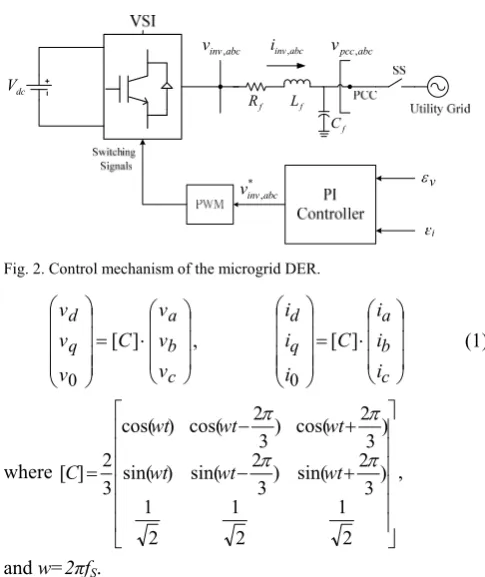
Fig. 2. Control mechanism of the microgrid DER.
c b a q d v v v C v v v ] [ 0 , c b a q d i i i C i i i ] [ 0 (1) where 2 1 2 1 2 1 ) 3 2 sin( ) 3 2 sin( ) sin( ) 3 2 cos( ) 3 2 cos( ) cos( 3 2 ] [ wt wt wt wt wt wt C ,
and w=2πfS.
The P/Q control is mainly achieved by controlling the real and reactive reference currents in d- and q-axis. Equation (2) shows the power calculation in the dq0 reference frame. Since vq is 0, the inverter output reference current is given by (3). 3 2 3 2 / ) i v i v ( Q / ) i v i v ( P q d d q ref q q d d ref (2) d ref qref d ref dref v Q i v P i 3 2 3 2 (3)
As illustrated in Fig. 2, after determining the reference current signals of (3), they are compared with the real inverter output currents and then obtain the error signals, εi and εv. The error signals are applied to the PI controllers, and their outputs are computed with vpcc,d, vpcc,q, iinv,dwL and
iinv,qwL terms to generate the reference voltages, and [8-10]. Then, the switching signals are produced by PWM and are input to the VSI. Figure 3 depicts the control block diagram to determine inverter reference output voltages in dq0 reference frame. The abc reference voltages are then obtained by (1).
ref P d pcc v , ref Q d pcc v , d inv i , q inv i , qref i dref i q pcc v , * ,q inv v * ,d inv v
Fig. 3. Control block diagram for determining inverter reference output voltages.
C. Three-Phase Volt/Var Control
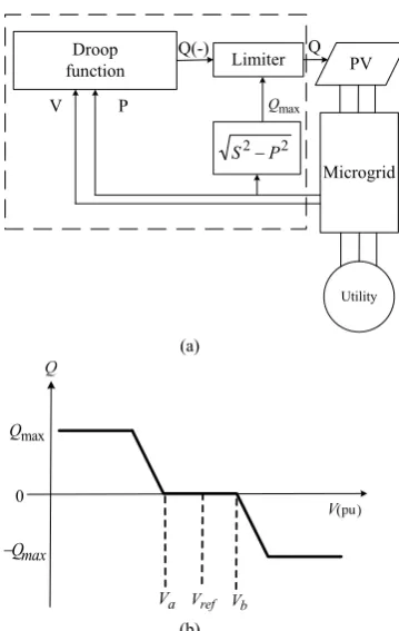
The Volt/Var control is implemented to supply the reactive power output based on controlling the PV inverter voltage magnitude [11]. In the Volt/Var control, the voltage control is accomplished with a linear droop characteristic, which determines the reactive power injection as a function of the voltage magnitude at the PV inverter terminals [12]. Figure 4 shows the functional blocks of the three-phase Volt/Var controller and the inverter Volt/Var droop characteristic.
The Volt/Var control is to obtain the active power output of PV to compute maximum reactive power of (4), which is to limit the output without exceeding the inverter apparent power rating, S, and then determine the microgrid voltage magnitude for the droop function to compute the reactive power output. If the reactive power output is within the limit, the PV output is to maintain voltage magnitude that meets the regulation requirement.
2 2 P
S
Qmax (54)
[image:2.595.45.288.390.679.2]power within the limit. This is a commonly seen PV operating mode because of the voltage rise phenomenon caused by PV system. Nevertheless, this controller can also contribute to the mitigation of low-voltage situation such as the locations are remote from the substation under heavy load conditions, when the voltage drops below Va shown in Fig. 4(b). Utility PV Microgrid Droop function Limiter 2 2 P S
P Qmax
V
Q(-) Q
(a)
a
V Vref Vb
0 max Q max Q (b)
Fig. 4. (a) Block diagram of a PV inverter with Volt/Var controller, (b) the droop function.
D. Volt/Var Control of Single-Phase Inverter
The Volt/Var control is also used in the single-phase inverter. For such inverters, a widely-used control scheme is to model three-phase inverter through time delay, which is to convert the 3-phase AC system to a 2-phase system using the Park transformation and then convert to a 2-phase dc system [13]. Another control method is to use a different algorithm to control the inverter. In the proposed control scheme, the active power (P) and reactive power (Q) of the single-phase inverter are shown in (5), respectively.
( c t)l t t c l t l t c l t c V V X V V cos V X V Q X V V sin X V V P (5)
where VC and Vt are the inverter rms output voltage VC and the PCC voltage Vt, α is the phase angle difference of VC and
[image:3.595.319.533.48.159.2]Vt, and Xl is the equivalent reactance of the transformer. Thus, the active power is controlled by regulating the phase angle difference α of VC and the reactive power is controlled by the regulating of the VC and Vt. The simulation model is shown in Fig. 5, where the proposed decoupled control algorithm can control the inverter’s active power and reactive power independently and instantaneously. The fast response of the control algorithm ensures that the PV system can provide service under different system conditions, both in steady and transient states and in grid-connecting and islanding modes. phase V phase I inv V mag inv V , P Q * magitude V * angle V
Fig. 5. Single-phase inverter Volt/Var control.
E. Voltage/Frequency Control
If a cluster of DERs is operated within a microgrid connected to the utility network, all the inverters can be operated in P/Q mode because the microgrid has the voltage and frequency references. However, to operate the microgrid in islanding mode a voltage source inverter can be used to provide a reference for frequency and to smoothly switch to islanding operation without changing the control mode of any other inverters.
The inverter output frequency is a produced sine wave signal inside the controller. That signal is used as a directional reference vector, which is in the d-axis of the dq0
reference frame. In this reference frame, the value of d-axis and q-axis output voltages are
Vdref = U0 , Vqref = 0 (6) where both Vdref and Vqref are the reference of the d-axis and q-axis rms voltages, respectively. When the microgrid operates at nominal voltage, U0 = 1 pu.
To achieve the voltage control, it usually uses voltage and current double close-loop controls. Voltage loop adjusts the magnitude of the output voltage. The output of voltage loop serves as the current loop input reference. The output current references of the voltage loop are given in (7).
q qref iqu pdu d dref idu pdu V V s K K V V s K K qref dref i i (7)The output voltages of the current loop are given in (8).
V V iq id q qref iq pq d d dref id pd q d i i s K K wLi i i s K K wLi V (8) [image:3.595.83.263.137.421.2]Figures 6 and 7 depict the functional blocks of the double control loops. d V q V dref i qref i qref V dref V
[image:3.595.284.550.474.722.2]d inv
i ,
q inv
i ,
qref
i
dref
i
* ,q inv
v
* ,d inv
v
[image:4.595.307.541.50.309.2]d V
Fig. 7. Control block diagram of the current loop.
When the fault occurs at the utility grid side, the microgrid will be disconnected from the grid. MGCC will detect the current drop at PCC and commands the energy storage system to operate at V/F control mode. When the fault is clear, MGCC will decide when the microgrid is reconnected to the grid based on the synchronization conditions related to phase sequence, frequency, and voltage deviations.
III. REVIEW OF THREE INVERTER CONTROL STRATEGIES Microgrid has many different control strategies for different operation scenarios. In this paper, P/Q control, droop control, and V/F control of inverters are used in grid-connecting and islanding modes. P/Q control is adopted in all DERs except the DER is under islanding control. The P/Q control can generate the preset power (Pref and Qref) to the grid and is independent of microgrid voltage and frequency, as shown in Fig. 8.
ref
[image:4.595.58.279.51.209.2]P Qref
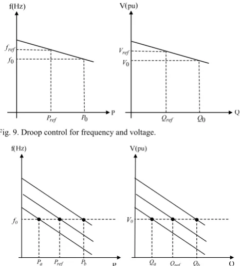
Fig. 8. Frequency and voltage droop characteristics under P/Q control. Droop control will change the output power which is varied with the microgrid voltage and frequency [14]. If the microgrid voltage and frequency are dropped, the DERs/energy storage systems will increase the active and reactive power output. Droop control can be used in two or more DERs which are controllable to supply power to the microgrid, as shown in Fig. 9.
V/F control will change the power output of the energy storage system to maintain the microgrid voltage and frequency at nominal values. Figure 10 illustrates the V/F control characteristics of an inverter.
ref P 0
f ref
f
0 P
0 V
ref V
0 Q
ref Q Fig. 9. Droop control for frequency and voltage.
ref P a
P Pb Qa Qref Qb
Fig. 10. Frequency and voltage droop characteristics under V/F control.
IV. CASE STUDY
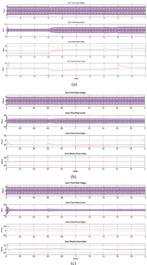
This paper applies Matlab/Simulink to develop the 380-V and 60-Hz INER three-zone microgrid model, as shown in Fig. 1. To simplify the modelling task and focus on assessing the effectiveness of the inverter controls of DERs and energy storage systems, most DERs are modeled as constant dc-voltage sources. The Simulink model of Fig. 1 is depicted in Fig. 11. The structure of the Zone 1 is illustrated in Fig. 12. There are three DERs and two controllable loads in Zone 1. Zone 2 includes a wind turbine and PV systems and Zone 3 includes a wind turbine and a microturbine. The microgrid is connected to the utility grid by a static transfer system (SS). Due to the space limit, only simulation parameters for Zone 1 are listed in Table 1.
[image:4.595.61.283.445.575.2]Fig. 11. Simulink model of the INER microgrid.
[image:5.595.56.270.245.377.2]Fig. 12. Structure of Zone 1 of the microgrid.
Table 1. Simulation parameters for Zone 1
Parameters Values
Energy Storage System
Inverter switching frequency 10 kHz Inverter filter inductance 2 mH Inverter filter capacitance 68.5 μF DC-link voltage 700 V Maximum active power 60 kW Maximum reactive power 100 kVAr
PV system
Inverter switching frequency 10 kHz Inverter filter inductance 2 mH Inverter filter capacitance 68.5 μF DC-link voltage 700 V Maximum active power 51.5 kW
Microturbine
Inverter switching frequency 10 kHz Inverter filter inductance 2 mH Inverter filter capacitance 68.5 μF DC-link Voltage 700 V Maximum active power 31.5 kW
PI Controller
Kp_P/Q 5
Ki_P/Q 500
Kp_V/F 6
Ki_V/F 30
TABLE 2.THE INITIAL CONDITIONS IN ZONE 1 TO ZONE 3SYSTEMS
Initial condition Zone 1 40 kW (0.4 pu) Load 1 30 kW (0.3 pu) Zone 2 40 kW (0.4 pu) Load 2 60 kW (0.6 pu) Zone 3 40 kW (0.4 pu) Load 3 30 kW (0.3 pu)
TABLE 3.SIMULATION SCENARIOS OF THE THREE-ZONE MICROGRID
Event Operation condition Time (s) 0 Three zones operated normally 0 2 Microgrid operated under islanding mode A fault occurred at the utility grid side 0.6 3 Microturbine started output 0.2 pu active power 1.4 4 Microgrid back to grid-connected mode 1.6
0 0.2 0.4 0.6 0.8 1 1.2 1.4 1.6 1.8 2
0.9 0.95 1 1.05
1.1 Microgrid Voltage Magnitude
time ( s )
V
(
p
u
)
0 0.2 0.4 0.6 0.8 1 1.2 1.4 1.6 1.8 2
59.6 59.8 60 60.2
60.4 Microgrid Frequcncy
time ( s )
f
(
H
z
[image:5.595.305.551.312.755.2])
Fig. 13. RMS voltage and frequency of the microgrid.
(a)
(b)
(c)
[image:5.595.54.282.418.684.2]V. CONCLUSION
In this paper, the inverter controls that adopted for DERs and energy-storage system in the microgrid have been presented. The inverter control is implemented to deal with the microgrid for normal operation under both grid-connected and islanding modes. Under the grid-connected mode, the DERs generate the predetermined power according to the characteristics of the DER units. The PV Volt/Var control is used to control the voltage magnitude of the microgrid. The single-phase PV system is also included in the system. When the islanding is detected, the microgrid is disconnected from the utility grid, which is commanded by the MGCC. At the same time, the energy storage system switches to V/F mode from P/Q mode to provide active power to critical loads and maintain the voltage and frequency of the microgrid.
The performances of the described inverter controls are verified through simulations using Matlab/Simulink. Results show that the functions of the controllers adopted in the study performs as expected. The microgrid can reliably operate either under grid-connected or islanding mode.
REFERENCES
[1] N. Jayawarna, X. Wu, Y. Zhang, N. Jenkins, and M. Barnes, “Stability of a MicroGrid,” Proc. 3rd IET International Conference on Power Electronics, Machines and Drives, pp. 316-320, March 2006. [2] J. A. P. Lopes, C. L. Moriera, and F. O. Resende, “Control strategies for
microgrids black start and islanded operation,” Int. J. Distrib. Energy Res., vol. 1, no. 3, pp. 241-261, 2005.
[3] B. S. Hartono, Y. Budiyanto, R. Setiabudy, “Review of microgrid technology,” Proc. International Conference on QiR (Quality in Research), pp. 127-132, June 2013.
[4] M. Milosevic and G. Andersson, “Generation control in small isolated power systems,” Proc. 37th North Amer. Power Symp., pp. 524-529, 2005.
[5] R. H. Lasseter et. al., “Integration of Distributed Energy Resources: The CERTS MicroGrid Concept,” Lawrence Berkeley National Laboratory,
LBNL-50829, April 2002.
[6] M. G. Villalva, J. R. Gazoli, and E. R. Filho,” Comprehensive Approach to Modeling and Simulation of Photovoltaic Arrays,” IEEE Trans. on Power Electronics, Vol. 24, No. 5, May 2009.
[7] P. Piagi and R. H. Lasseter, “Autonomous control of microgrids,” Proc. 2009 IEEE PES General Meeting, Montreal, July 2006.
[8] C. Jin, P. C. Loh, P. Wang, Y. Mi, and F. Blaabjerg, “Autonomous operation of hybrid ac-dc microgrids,” Proc. 2010 IEEE Int. Conf. Sustainable Energy Technologies (ICSET), Sri Lanka, 2010.
[9] M. Saeedifard, M. Graovac, R. F. Dias, and R. Iravani, “DC power systems: Challenges and opportunities,” Proc. 2010 IEEE PES General Meeting, July 2010.
[10]S. R. Guda, C. Wang, and M. H. Nehrir,” A Simulink-based microturbine model for distributed generation studies,” Proc. 37th Annu. North Amer. Power Symp., pp. 269-274, 2005.
[11]P. Jahangiri and D. C. Aliprantis, “Distributed volt/var control by PV inverters,” IEEE Trans. Power Syst., vol. 28, no. 3, pp. 3429-3439, Aug. 2013.
[12]Y. Xu, H. Li, D. T. Rizy, F. Li, and J. D. Kueck, “Instantaneous active and nonactive power control of distributed energy resources with a current limiter,” Proc. 2010 IEEE Energy Conversion Congr. Expo, pp. 3855-3861, 2010.
[13]V. Dixit, M. B. Patil, M. C. Chandorkar,” Real Time Simulation of Power Electronic Systems on Multi-core Processors,” Proc. 2009 International Conference on Power Electronics and Drive Systems, pp. 1524-1529, Nov. 2009.
[14]G. W. Chang, G. F. Zeng, H. j. Su, and L. Y. Hsu. “Modelling and simulation for INER AC microgrid control,” Proc. 2014 IEEE PES General Meeting, July 2014.