A Pattern-based Approach for the Combination of Different Layout Algorithms in Diagram Editors
Dissertation
zur Erlangung des akademischen Grades eines Doktors der Naturwissenschaften (Dr. rer. nat.)
vorgelegt von Sonja Maier im Juni 2012
Vorsitzender der Kommission: Prof. Dr. Peter Hertling 1. Berichterstatter: Prof. Dr.-Ing. Mark Minas 2. Berichterstatter: Prof. Paolo Bottoni
1. Prüfer: Prof. Dr. Gunnar Teege
2. Prüfer: Prof. Dr.-Ing. Wolfgang Reinhardt Tag der mündlichen Prüfung: 24. September 2012
Universität der Bundeswehr München Fakultät für Informatik
Abstract
Nowadays, visual languages are widely used. Examples of visual languages are graphs and class diagrams. The usage of meta-tools minimizes the effort that is needed for the creation of visual language editors. By the help of an abstract specification, a large amount of the functionality of an editor may be described. Unfortunately, in most commonly used meta-tools, the definition of the layout behavior is only insufficiently supported. In order to be able to develop a fully functional visual language editor, which lets the editor user draw comprehensible and visual appealing diagrams, this part is of great importance.
In this thesis, a pattern-based layout approach for the specification of layout behavior is described. The approach is based on meta-models and enables the combination of all commonly used approaches for the definition of layout behavior. Amongst others, graph drawing algorithms and constraint-based approaches can be used. Furthermore, a newly developed rule-based ap-proach can easily be integrated.
Layout patterns are the main concept of the approach: Each layout pattern encapsulates certain layout behavior. Several layout patterns may be applied to a diagram simultaneously, even to diagram parts that overlap. A control algorithm that is included in the approach deals with such situations. One import characteristic of the approach is that the layout is continuously maintained during diagram modification, and that it is updated at runtime. The possibility to reuse layout patterns, and to integrate them in a huge variety of different visual language editors are two more characteristics. Based on the layout approach, several layout features were developed: User-controlled layout behavior allows the editor user to influence the layout at runtime by applying layout patterns to certain parts of the diagram. For instance, the editor user can align components horizontally by applying the horizontal alignment pattern. This layout behavior is preserved until the edi-tor user explicitly removes it again. The ediedi-tor is capable of suggesting layout patterns being applied to certain parts of the diagram. This feature is called
layout suggestions. For instance, the editor suggests to apply the horizontal iii
iv
alignment pattern to components that are almost horizontally aligned. Fur-thermore, the editor can even automatically apply these suggestions. This feature is named ad-hoc layout.
In this thesis, the practical relevance of the introduced approach is demon-strated: Several layout patterns are specified and used to define the layout behavior of four DiaMeta editors, namely a graph editor, a class diagram editor, a GUI forms editor, and a VEX diagram editor. Additionally, they are used to define the layout behavior of one GEF editor, namely a graph editor.
Contents
1 Introduction 1
1.1 Context of the Work . . . 2
1.2 Overview of the Proposed Approach. . . 6
1.3 Scientific Contributions . . . 10
1.4 Thesis Outline. . . 11
2 Related Work 15 2.1 Visual Language Editors . . . 15
2.2 Design Patterns . . . 16
2.3 Constraints . . . 18
2.4 Layout in Visual Language Editors . . . 22
2.5 Human Computer Interaction . . . 23
2.6 Summary . . . 24 3 Running Examples 27 3.1 Graphs . . . 28 3.2 Class Diagrams . . . 29 3.3 GUI Forms . . . 32 3.4 VEX Diagrams . . . 33 3.5 Layout Behavior . . . 36 3.6 Summary . . . 45
4 Pattern Concept and Reusability 47 4.1 General Idea . . . 47
4.2 Meta-Models and their Correlation . . . 49
4.3 Layout Patterns . . . 63
4.4 Specification and Integration of Algorithms . . . 66
4.5 Atomic Layout Patterns . . . 76
4.6 Summary . . . 78 v
vi CONTENTS 5 Control Algorithm for Pattern Combination 79
5.1 General Idea . . . 79
5.2 Definitions . . . 80
5.3 Control Algorithm . . . 83
5.4 Example Execution of the Algorithm . . . 85
5.5 Characteristics of the Algorithm . . . 97
5.6 Future Work . . . 99
5.7 Summary . . . 100
6 User-Controlled Layout Behavior 103 6.1 Instantiation of Layout Patterns . . . 103
6.2 Examples of User-Controlled Instantiation . . . 106
6.3 Useful Features . . . 109
6.4 Future Work . . . 116
6.5 Summary . . . 117
7 Layout Suggestions and Ad-hoc Layout 119 7.1 Layout Suggestions . . . 119
7.2 Ad-hoc Layout . . . 123
7.3 Future Work . . . 127
7.4 Summary . . . 128
8 Examples of Layout Patterns 129 8.1 Examples of Layout Patterns . . . 129
8.2 Integration of Layout Patterns in an Editor . . . 155
8.3 Summary . . . 158 9 Evaluation 159 9.1 User Study . . . 159 9.2 Performance Evaluation . . . 164 9.3 Summary . . . 187 10 Conclusions 189 10.1 Summary . . . 189 10.2 Application Areas . . . 190 10.3 Future Directions . . . 192 10.4 Summary . . . 196
A Specification and Implementation 197 A.1 Layout Framework . . . 197
A.2 Integration into Diagram Editors . . . 198
Chapter 1
Introduction
“A picture is worth a thousand words.” This sentence dates back to Ivan Turgenev, who states in his book Fathers and Sons [110]: “A picture shows me at a glance what it takes dozens of pages of a book to expound.”
Following this principle, diagrams are used almost everywhere. In computer science, for instance, UML diagrams are used for the specification, the con-struction and the documentation of software parts.
Diagrams can either be drawn with the help of pen and paper, or they can be created with the help of a computer. Here, we distinguish software that solely allows to draw diagrams, and software that not only allows to draw diagrams, but also provides further functionality, such as syntax-directed editing. Diagrams are an abstract representation of information [118]: The structure of a diagram usually has meaning, while the layout of a diagram, i.e. the shape and the arrangement of components, usually has no meaning. Instead, the user may define the layout in order to emphasize certain aspects and (or) to improve readability.
Some visual languages have particular drawing conventions, e.g. generaliza-tion in class diagrams is usually drawn from top to bottom. Others allow the user to freely shape and arrange components, e.g. nodes in a graph are usually positioned arbitrarily. Therefore, for some types of diagrams, the layout is typically created automatically. For other types of diagrams, an
automatic layout only partially makes sense. For those, a user-controlled layout is indispensable.
In most visual language editors, users are forced to manually maintain the layout desired. As an alternative, the layout engine could maintain the layout automatically, which means that so-calledpermanent layout is supported. In order to enable automatic layout, user-controlled layout and permanent layout, a diagram editor is needed that incorporates a powerful and flexible layout engine. In an interactive environment, performance is usually the
2 CHAPTER 1. INTRODUCTION limiting factor. Throughout the last years, computers got more and more powerful, which clears the way for a powerful and flexible layout engine. In this thesis, an approach for layout computation is introduced that is specif-ically tailored to an interactive environment, such as visual language editors. With the help of this approach, the user is able to create a diagram editor and its layout engine with small effort.
This chapter is structured as follows: The context of this thesis is outlined in Section1.1. An overview of the proposed approach is given in Section1.2. The scientific contributions of this thesis are summarized in Section1.3, and an outline of it is given in Section 1.4.
1.1
Context of the Work
The approach for layout computation presented in this thesis is tailored to the interactive nature of visual language editors. It is designed for meta-model based visual language editors, whose syntax is defined by the help of EMF [102], as it is done, for instance, in DiaMeta [86,87] editors and in GEF [30] editors.
1.1.1
Visual Language Editors
As already stated, visual languages are used almost everywhere. Some ex-amples of visual languages are graphs, class diagrams, GUI forms and VEX [20] diagrams. These visual languages will serve as the running examples throughout this thesis.
Abstract and Concrete Syntax
The core of a visual language is its abstract and concrete syntax specifica-tion. Literature often provides different understandings of the termsabstract syntax and concrete syntax. In this thesis, these terms are used as follows: The abstract syntax (AS) of a visual language describes the “underlying” structure of a diagram of the visual language. The concrete syntax (CS) describes the visual appearance of the visual language elements.
For instance, the abstract syntax describes a graph as a set of nodes and a set of directed edges, where each edge exactly connects two nodes. As can be seen in Figure 1.1, the graph consists of the nodes A, B, C, D and E, and the four edges that connect the nodes Aand B, Aand C,B and Dand B and E. In contrast, the concrete syntax of a visual language describes graphs as circles, whose center is at a certain (x, y)-position (e.g. (0,0)),
1.1. CONTEXT OF THE WORK 3 and arrows, whose start point and end point are at certain (x, y)-positions (e.g.[(0,0),(−1,1)]). As can be seen in Figure1.1, the graph consists of circles at the positions (0,0), (−1,1), (1,1), (−2,2) and (0,2), and arrows at the positions [(0,0),(−1,1)],[(0,0),(1,1)], [(−1,1),(−2,2)] and [(−1,1),(0,2)].
A
B C
D E
Figure 1.1: Visual Language: Graphs
One might ask, whether or not one of the equations AS ⊆CS or CS ⊆AS holds. In general, none of these equations must hold. The concrete syntax may contain some information that is not part of the abstract syntax, for example, information about the position or size of components. The abstract syntax may contain some information that is not visualized, for instance, in case of class diagrams, program code that is associated with a method. Eclipse Modeling Framework (EMF)
The Eclipse Modeling Framework (EMF) [102] is a modeling framework that provides a code generation facility: From a model specification, code is gener-ated, which comprises a set of classes that enable creating and editing model instances. EMF comprises a meta-model, called Ecore, for describing the models and it comprises the runtime support for the models. In this thesis, meta-models are described by the help of Ecore. Hence, Ecore serves as a meta-meta-model in this case.
DiaMeta
DiaGen and DiaMeta [86,87] are frameworks for prototyping visual language editors. In DiaMeta, the abstract syntax of a visual language is defined with Ecore, whereas in DiaGen [85], it is defined via a grammar. The rest of the editor is specified by the help of the DiaGen-DiaMeta framework. One char-acteristic of DiaGen and DiaMeta is that they support structured editing as well as freehand editing. Structured editors offer the user editing operations
4 CHAPTER 1. INTRODUCTION that transform correct diagrams into other correct diagrams. Freehand edi-tors, on the other side, allow to arrange diagram components on the screen without any restrictions.
Graphical Editing Framework (GEF)
The Graphical Editing Framework (GEF) [30] is a framework that enables the creation of graphical editors, such as visual language editors, for the Eclipse platform. The abstract syntax of a visual language of such an editor can, for instance, be defined with EMF.
1.1.2
Layout in Visual Language Editors
Literature often provides different understandings of the term layout. In this thesis it is defined as follows: Layout comprises all facets of the shape and the arrangement of diagram components. This also comprises the shape and the arrangement of a single component. More precisely, the layout of a component is defined by a set of attributes and their corresponding values. E.g. a node is defined by its (x, y)-position and by its radius. The layout of a diagram is defined by the layout of all components, the diagram consists of, and hence, a set of attributes and their corresponding values.
Updating the layout of a diagram usually implies the change of the concrete syntax of the diagram, only. It should not imply the change of the abstract syntax.
Layout in a Static and a Dynamic Context
Layout computation in a static context means that a diagram is visualized, often without having any previous layout information available. Layout com-putation in a static context is usually less time-critical than in a dynamic one. In contrast, layout computation in a dynamic context usually means that a user changes a diagram, and afterwards the layout engine updates the diagram. The layout engine should take previous layout information into account, and should present the result immediately. Hence, performance is a big issue.
Automatic graph layout dominates the research in the area of layout. As a consequence, graph aesthetics [109] are usually the main measure for the quality of the layout, and hence, for the quality of the layout algorithm. Ex-amples of aesthetic criteria are symmetry and edge crossing minimization. The overall goal of these criteria is that the layout of a diagram maximally
1.1. CONTEXT OF THE WORK 5 supports the user to understand and remember the information that is visu-alized [114].
Graph aesthetics are a good measure in a static context, but not in a dynamic one, such as in graph editors or visual language editors. Here, other criteria should be used, such as mental map preservation [16]: When looking at a drawing, the user has to build a mental map. This essentially means that he or she has to understand the structure and the meaning of the diagram. In a dynamic context, the diagram as well as the layout of a diagram change over time, and the user has to update his or her mental map. The user can be supported in two ways: Layout changes can be minimized, or they can be highlighted and animated.
In summary, in a static context, the following is very important: • Graph aesthetics and other aesthetics criteria.
In a dynamic context, the following is important:
• Performance in terms of response time of the system.
• Mental map preservation, which means that the user can follow the changes performed in the diagram.
Layout Modifications
Layout algorithms are used for the definition (implementation) of layout behavior. Examples are graph drawing algorithms, such as the Sugiyama algorithm [109]. Layout algorithms change the layout of a diagram in a sense that attribute values are changed. One can distinguish layout algorithms that imply “big changes”, and layout algorithms that imply rather “small changes”.
Usually, only a small number of layout algorithms, which imply “big changes” in the diagram, are applied simultaneously to a diagram. Examples are graph drawing algorithms that rearrange the whole diagram.
Usually, a high number of layout algorithms, which imply rather “small changes” in the diagram, are applied simultaneously to a diagram. Examples would be an algorithm that aligns components vertically or an algorithm that takes care of the correct connection of edges. This kind of layout behavior is usually neglected by editor developers, and often hand-coded and hard-wired in the specific system.
6 CHAPTER 1. INTRODUCTION Standardization and Formalization of Layout
There is a lack of standardization and formalization concerning the layout functionality of visual language editors. As a consequence, each editor de-veloper is challenged by the layout engine, and often neglects this part of the editor. It is a common fact that layout is a demanding task. Neverthe-less, developers tend to reinvent the wheel, meaning that the layout engine is built from scratch for every tool. To avoid this needless effort, a framework is needed, which enables and simplifies the reuse of certain layout behavior. Layout Approaches
Several layout approaches that can be used in a diagram editor exist. As experience shows, developers tend to use only one layout approach and utilize it for the specification of every layout behavior they want. Each layout approach has its own strengths, and therefore a combination of different approaches is more reasonable than the usage of only one of them.
Most tools either solely provide automatic layout, which may not be influ-enced by the user, or only provide a quite restricted form of user-controlled layout. In contrast, we are convinced that tools should provide the possibility to allow the user to strongly influence the layout at runtime.
1.2
Overview of the Proposed Approach
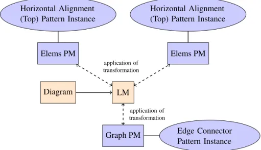
In the following, an overview of the pattern-based layout approach, which is introduced in this thesis, is given. The cornerstones of the approach are the concept of layout patterns and an algorithm that controls the combination of different layout patterns. Based on the layout approach, several layout features were developed. The most important ones are user-controlled layout behavior, layout suggestions and ad-hoc layout. In [72], an overview of the layout approach and its integration into an editor is given.
The purpose of a visual language editor is to draw diagrams. As shown in Figure 1.2, internally, a diagram is represented by a language-specific model (LM). This language-specific model is an instance of a language-specific meta-model (LMM), which defines the abstract and concrete syntax of the visual language. The current layout of a diagram is represented by the LM, whereas the layout behavior of a diagram editor is defined by a set of layout pattern instances. Each layout pattern, in turn, encapsulates certain layout behavior. Editing a diagram comprises the creation and deletion of diagram compo-nents. It also comprises the modification of the layout of a diagram, e.g. the editor user can move or reshape diagram components. As visualized in
1.2. OVERVIEW OF THE PROPOSED APPROACH 7 Editor Diagram Language-Specific Model (LM) Language-Specific Meta-Model (LMM) instance of Edge Connector Pattern Layout Pattern Instance Horizontal Alignment (Top) Pattern Layout Pattern Instance Layout Pattern Instance
correspondence correspondence correspondence instance of instance of instance of
uses
Figure 1.2: Overview of the Approach
Figure 1.2, after the user has edited a diagram, the LM that corresponds to this diagram is automatically created (updated). Furthermore, several layout pattern instances are automatically created (updated). Based on the LM and the layout pattern instances, the new layout of the diagram is auto-matically computed, and the diagram is updated accordingly. For instance, if the editor user moves circle A in the diagram shown in Figure1.3, the four outgoing arrows are automatically updated.
A
B
C
D E
8 CHAPTER 1. INTRODUCTION
1.2.1
Concept of Layout Patterns
A layout pattern encapsulates certain layout behavior. An example is the edge connector pattern, which ensures that edges are correctly connected to nodes. Another example is the horizontal alignment (top) pattern, which makes sure that a certain set of nodes is horizontally aligned at the top. After the user has edited a diagram, several pattern instances are created, and a correspondence between the LM and each of these pattern instances is established (cf. Figure 1.2).
A layout pattern may be instantiated one or more times for the same diagram. The instantiation of a layout pattern is either performed automatically, or it is triggered by the user. For instance, the edge connector pattern is instantiated automatically. For the diagram shown in Figure 1.3, one pattern instance is created for the nodes A, B, C, D and E together with the four edges. In contrast, the instantiation of the horizontal alignment (top) pattern is triggered by the user. For the diagram shown in Figure1.3, for instance, two pattern instances could be created - one for the nodesA and E, and one for the nodes B, C and D. The edge connector pattern instance and the two horizontal alignment (top) pattern instances are shown in Figure1.2. A layout pattern (cf. Figure 1.4) is defined on top of a pattern-specific meta-model (PMM). It has one or more associated p-constraints (pattern-constraints), and each p-constraint consists of one predicate, which has one or more associated rules. The predicates of all pattern instances present in a diagram assure the layout of the diagram. The layout of a diagram is correct if all predicates hold. The layout of a diagram is incorrect and needs to be updated if one or more predicates are broken. The rules give guidance on how to repair broken predicates.
Layout Pattern P-Constraint * Predicate * Rule PMM Layout Pattern Instance * *
1.2. OVERVIEW OF THE PROPOSED APPROACH 9 For instance, the horizontal alignment (top) pattern has the associated pred-icate c1.y = c2.y. This predicate has the two associated rules c1.y := c2.y and c2.y := c1.y. c1 and c2 are two components. c1.y is the y-position of the first component, andc2.y is they-position of the second component. For the example mentioned above, the predicate as well as the associated rules are “instantiated” several times: For the alignment of the componentsAand E, they are instantiated for the pair of components {A, E}. For the align-ment of the components B, C and D, they are instantiated for the pairs of components {B, C}and {C, D}.
First ideas of the layout approach are described in [63, 64, 65, 61, 69, 67]. A more detailed description can be found in Chapter 4.
Layout Algorithms
Rules give some guidance on how to repair broken predicates. Each of these rules encapsulates a layout algorithm. The most commonly used types of layout algorithms are graph drawing algorithms, constraint-based (layout) algorithms and rule-based (layout) algorithms. Rule-based algorithms are introduced in this thesis, and are specifically tailored to the interactive nature of diagram editors.
The different types of algorithms and their integration into the pattern-based layout approach are described in [68]. A more detailed description can be found in Chapter 4.
1.2.2
Control Algorithm for Pattern Combination
The control algorithm for pattern combination is essentially a local propaga-tion-based constraint solver that uses backtracking. It gets the set of layout pattern instances that are present in a diagram as input. The purpose of the control algorithm is to find a valid layout after user modification. The algorithm checks all (potentially violated) predicates. For each violated pred-icate, it applies one associated rule, which in turn triggers the application of the encapsulated layout algorithm. This way, the rule changes one or more attribute values, in order to repair the predicate.
In [70], the control algorithm is described. A more detailed description can be found in Chapter 5.
1.2.3
User-Controlled Layout Behavior
To support the user in an interactive environment, it is not sufficient to apply the same layout patterns in every situation. Instead, the user wants to alter
10 CHAPTER 1. INTRODUCTION the layout behavior at runtime. To do so, the editor user has the possibility to manually create and delete pattern instances: He or she may choose a part of the diagram and the layout pattern to be applied to this part. For instance, the editor user may apply the horizontal alignment (top) pattern to the circlesB, C and D of Figure1.3. As a consequence, the three circles are horizontally aligned.
A detailed description of user-controlled layout behavior can be found in Chapter 6.
1.2.4
Layout Suggestions and Ad-hoc Layout
Layout suggestions and ad-hoc layout are two features that are built upon the pattern-based layout approach.
After the editor user selects a certain part of a diagram, the layout engine is able to determine all layout patterns that can potentially be applied to this part. The layout engine can then further compute the attribute changes that become necessary after one of these layout patterns is applied. Based on this information, the layout engine can suggest layout patterns whose application results in small modifications of the layout of the diagram. For instance, the editor user selects the components B, C and D of Figure 1.3. As these components are almost horizontally aligned, the layout engine suggests to apply the horizontal alignment (top) pattern.
Automatic ad-hoc layout goes even one step further: While the editor user edits the diagram, layout patterns whose application results in small modi-fications of the layout of the diagram are automatically applied. The layout patterns are not only applied to the components selected, but to the com-ponents selected together with some other comcom-ponents. For instance, the editor user moves the componentB upwards (cf. Figure 1.3). As soon as the components B, C and D are almost horizontally aligned, the layout engine automatically applies the horizontal alignment (top) pattern.
In [73], layout suggestions and ad-hoc layout are described. A more detailed description can be found in Chapter 7.
1.3
Scientific Contributions
This thesis provides the following scientific contributions:
• A pattern-based layout approach has been developed. The approach en-ables the definition of layout patterns, which are language-independent, and which may be integrated into different visual language editors.
1.4. THESIS OUTLINE 11 • A control algorithm has been developed, which allows for a flexible
combination of different layout patterns.
• Based on the pattern-based layout approach and the control algorithm, several layout features were developed. The most import ones are user-controlled layout behavior, layout suggestions and ad-hoc layout. The applicability of the presented approach is justified by the following:
• The pattern-based layout approach as well as the layout features were integrated in DiaMeta editors as well as GEF editors.
1.3.1
Research Methodology
The goal of this thesis was the development of a layout approach, which seamlessly integrates with the editor generation framework DiaMeta. In this environment, the layout is updated continuously, beautifying the diagram while the user modifies the diagram. Furthermore, the editor user is able to influence the layout by moving or reshaping components and by applying layout patterns to certain parts of the diagram.
The conceptual design and the implementation of the new layout approach was supported by a user-centered design process. In several iterations, a prototype of the layout framework was created, taking the findings of a user study and the feedback of editor users into account. This iterative process focused on the user requirements and was driven by an evaluation of each iteration.
1.4
Thesis Outline
• Related work is discussed in Chapter 2. Related work concerning vi-sual language editors and generation frameworks for vivi-sual language editors is sketched in Section 2.1. An overview of related work in the area of patterns and pattern formalization is given in Section 2.2. In Section2.3, related work concerning constraints in visual language ed-itors is discussed. Related work concerning layout in visual language editors is described in detail in Section 2.4. Related work in the area of human computer interaction is outlined in Section 2.5.
• In Chapter3, four visual languages are introduced: Graphs (Section3.1), class diagrams (Section 3.2), GUI forms (Section 3.3) and VEX dia-grams (Section 3.4). In Section 3.5, the layout behavior is described that is included in editors for these four visual languages.
12 CHAPTER 1. INTRODUCTION • Chapter 4 introduces layout patterns as means to encapsulate certain layout behavior. Based on this concept, an algorithm automatically computes the layout, as described in Chapter 5. The general con-cept of the pattern-based layout approach is outlined in Section 4.1. The different meta-models, namely the language-specific meta-model, the pattern-specific meta-models and their correlation are described in Section4.2. In Section 4.3, the concept of layout patterns is discussed in detail. In Section4.4, it is explained how the different types of algo-rithms, namely graph drawing algoalgo-rithms, constraint-based algorithms and rule-based algorithms, are specified and integrated. In Section4.5, the concept of atomic layout patterns is introduced.
• In Chapter5, details are given about the control algorithm whose pur-pose it is to control the combination of different layout patterns. The general idea of this control algorithm is sketched in Section5.1. In Sec-tion5.2, some definitions are given. The control algorithm is described in detail in Section 5.3, and two examples are given in Section 5.4. Some characteristics of the algorithm are discussed in Section 5.5. In Section5.6, future work is outlined.
• The user-controlled instantiation of layout patterns and some special features that are useful in the context of user-controlled instantiation of layout patterns are described in Chapter6. The automatic and user-controlled instantiation of layout patterns is discussed in Section 6.1. In Section6.2, two examples of user-controlled instantiation are given. Some special features that are useful in the context of user-controlled instantiation of layout patterns are described in Section 6.3. In Sec-tion 6.4, future work is outlined.
• In Chapter7, the concept of layout suggestions and the concept of ad-hoc layout are described, two features that are based on the idea of user-controlled layout behavior. The concept of layout suggestions is discussed in Section 7.1. In Section 7.2, the concept of ad-hoc layout is described. In Section7.3, future work is outlined.
• In Chapter 8, several layout patterns are described, and their inte-gration in diagram editors is discussed. In Section 8.1, several layout patterns are described in detail. In Section8.2, it is discussed how these layout patterns are integrated in the editors described in Chapter3. • An evaluation of the approach in terms of usability and in terms of
performance is given in Chapter9. A user study, which aims at identi-fying layout patterns that are commonly “needed” in diagram editors,
1.4. THESIS OUTLINE 13 is described in Section 9.1. In Section 9.2, a performance evaluation is presented.
• The thesis is concluded in Chapter 10. A summary is given in Sec-tion 10.1. In Section 10.2, some related areas are mentioned, which had a point of contact with this thesis. Some future directions are discussed in Section 10.3.
• In AppendixA, some specification and implementation details are given. Details about the layout framework itself are given in Section A.1. In Section A.2, some details are given about the integration of a layout engine, which is defined by the help of this framework, into DiaMeta editors and into GEF editors.
Chapter 2
Related Work
In this chapter, related work is discussed. Related work concerning visual language editors and generation frameworks for visual language editors is sketched in Section 2.1. An overview of related work in the area of patterns and pattern formalization is given in Section 2.2. In Section 2.3, related work concerning constraints in visual language editors is discussed. Related work concerning layout in visual language editors is described in detail in Section 2.4. Related work in the area of human computer interaction is outlined in Section 2.5.
2.1
Visual Language Editors
The aim of this thesis was to design a layout approach that is tailored to diagram editors (i.e. visual language editors), and also (to some extent) to diagram drawing tools.
A huge variety of diagram editors exist. Examples are graph editors, class diagram editors, GUI forms editors, VEX [20] diagram editors, mind map editors and business process model editors. Examples of diagram drawing tools are commercial tools such as Paint, Powerpoint or Visio.
2.1.1
Meta Tools
Diagram editors provide tool support for modeling techniques. They provide support for editing, simulation, validation, transformation, code generation, and so on. Meta tools provide support for specifying visual modeling tech-niques. They allow for the generation of visual modeling environments. They also allow for an automated or semi-automated support for developing dia-gram editors. They provide support for developing editors, simulation tools,
16 CHAPTER 2. RELATED WORK validation tools, transformation tools, code generators, and so on.
One can distinguish three kinds of meta tools: Generic tools, such as Rational Rose, are tools for one visual modeling technique with variants. Frameworks, such as GEF [30], are reusable and incomplete applications that can be com-pleted and customized in order to create specialized tools. Generators, such as DiaGen [85], DiaMeta [86, 87], MetaEdit+ [53] or VL-Eli [98], enable the specification of visual modeling environments, and specific tools may be generated from this specification.
The two most commonly used approaches for the specification of the abstract syntax of a visual language are graph transformation-based approaches, such as used within DiaGen, and meta-model-based approaches, such as used within GEF (in combination with EMF) and DiaMeta. In the first approach, symbols and relations are defined by type graphs, and the abstract syntax is defined by graph grammars. In the second approach, symbols and relations are described by class diagrams, and the abstract syntax is defined by well-formedness rules.
2.1.2
Comparison
The pattern-based layout approach presented in this thesis is integrated within DiaMeta editors and GEF editors, two types of editors that are de-fined using the meta-model-based approach. DiaMeta editors are built via a generator, whereas GEF editors are built upon a framework.
The meta-model-based approach was chosen, because it is more commonly used than the grammar-based approach. Another criterion for this choice is that EMF can be used for syntax specification in both cases. An editor that is built via a generator as well as an editor that is built upon a framework was chosen in order to cover a wide spectrum of editors.
2.2
Design Patterns
Design patterns [45] serve as the formal basis of the pattern-based layout ap-proach that is described in this thesis. A design pattern is a general reusable solution to a common problem within a certain context. It is not a finished solution that can be transformed directly into code. It is rather a template (or description), which gives guidance on how to solve a problem, and which can be used in many different situations. Hence, design patterns are formal-ized best practices.
Design patterns have their origins in interaction patterns [111, 108], which were invented by Alexander [1]. Interaction patterns are quite important in
2.2. DESIGN PATTERNS 17 practice today, and huge libraries of interaction patterns exist. Each interac-tion pattern (design rule) is a small part of the complete (design) knowledge. A “full realization” of interaction patterns as well as of design patterns is enabled by a formalization of the notion of patterns. Several approaches that aim at formalizing interaction patterns as well as design patterns exist. For instance, in [13], a formalization of interaction patterns is detailed, and in [14], a formalization of design patterns is described by the same authors. Both approaches are based on meta-models. Other formalizations are described, for instance, in [57, 76, 75, 24,38], to name just a few.
In [11,12], a suite of meta-models is proposed, which describe common types of visual languages. Amongst others, an editor for a certain visual language can be defined by specializing some of these meta-models that are relevant for the visual language.
2.2.1
Pattern-based Model Transformation
In [21], pattern-based model-to-model transformations are presented. The approach is based on patterns which describe positive and negative conditions that have to be satisfied by two models in order to be considered being consistent. This means that transforming the first model results in the second one. Patterns have a high-level semantics that enables the decision of whether or not two models are consistent. The patterns are translated into operational mechanisms, which are based on triple graph grammar rules [99].
2.2.2
Pattern-based Layout
In VL-Eli [98], tree grammars are used as the basis for specifying visual languages and layout. The approach presented in this thesis uses meta-models instead, because they are more widely used today. Similar to the approach presented in this thesis, layout is encapsulated in certain patterns.
2.2.3
Comparison
In this thesis, a new type of patterns, namely layout patterns, are introduced. A layout pattern is essentially a general reusable solution to a common layout problem. This solution is a finished solution, already, which can be directly transformed into code. The formalization of layout patterns is based on meta-models.
The pattern-based layout approach that is described in this thesis requires the transformation between different models. The transformation between these models follows a model-based approach.
18 CHAPTER 2. RELATED WORK
2.3
Constraints
Constraints have been used to maintain relationships between components from the very beginning of graphical user interfaces [106]. Constraints are declarative in a sense that they permit the developer to express what they wish to hold true, rather than to describe how to maintain these constraints. Constraints are especially well suited for graph and diagram layout. A thor-ough overview of the usage of constraints in diagram editors is given in [4]. A constraint system is usually limited by the expressiveness and the per-formance of the underlying constraint solver. One challenge a constraint solver has to tackle is dealing with under-constrained systems. In such a system, multiple possible solutions exist. In the course of the choice of a solution, the stability of the system has to be maintained: In case a system is under-constrained, and therefore several solutions exist, a solution should be chosen that “minimizes” the changes performed. Constraint hierarchies [9] address this issue, and remove ambiguities by over-constraining the system with constraints at a “lower” level.
2.3.1
Theory of Constraints
Three types of constraint solvers [4] are mainly used in diagram editors: Local propagation-based solvers, iterative numeric solvers and direct numeric solvers.
Local Propagation-based Solvers
Local propagation-based solvers are among the earliest developed solvers, and are quite simple: In a local propagation-based solver, changes are propagated through the diagram. The limitation of propagation-based solvers is their inability to consider more than one constraint at a time. Their strengths are their efficiency and their ability to handle constraints over arbitrary domains. Local propagation-based solvers that handle one-way constraints are distin-guished from those that handle multi-way constraints. E.g. the first kind of solver may maintain the constraint a = 2b+ 3c by setting a, whereas the second kind of solver may maintain this constraint by settinga,b and (or)c. The second kind of solvers is more powerful, and the underlying algorithms are more complex. Lessons learned from programmer’s experiences in the use of one-way constraints are described in [120]: Constraints should be al-lowed to contain arbitrary code, constraints are difficult to debug and better debugging tools are needed, and developers will use constraints to specify layout behavior, but must be trained to use them in another context. In
2.3. CONSTRAINTS 19 [97] and [119], the use of one-way constraints and multi-way constraints in diagram editors is compared. The user studies presented give evidence that both - one-way as well as multi-way constraints - are useful in the context of the definition of layout behavior. They also give evidence that multi-way constraints are more useful than one-way constraints.
There exists a huge variety of local propagation-based solvers. Prominent examples of such constraint solvers that handle multi-way constraints are Blue [40], DeltaBlue [39] and SkyBlue [96], just to mention a few of them. Other examples are Sketchpad [106] and ThingLab [8], two tools that include a local propagation-based solver.
Iterative Numeric Solvers
Iterative numeric solvers have also been used for quite a while. Their strength is that they are very general. Furthermore, they allow solving non-linear constraints simultaneously. Their drawback is that they are relatively slow, and hence, are not especially well suited for an interactive environment. Behind the scenes, relaxation is used. Relaxation is some sort of iterative “hill climbing” algorithm, and is used to find a local minimum. It does not find a global one.
The tools Sketchpad as well as ThingLab, for instance, use an iterative nu-meric solver as a fallback technique. This means that if the local propagation-based solver is not successful, an iterative numeric solver is used. Another tool that uses an iterative numeric solver is GLIDE [95].
Direct Numeric Solvers
Direct numeric solvers avoid the problems of iterative numeric solvers. Es-sentially, direct numeric solvers try to find a solution through direct manip-ulation of the constraints.
The easiest direct numeric solvers use Gaussian elimination. This type of constraint solver does only find solutions for a certain class of constraint satisfaction problems (CSPs). Furthermore, it only finds a unique solution if the system is not under-constrained. If there are no cycles, propagation can be used instead of Gaussian elimination.
An alternative is the Simplex algorithm. This type of constraint solver also does only find solutions for a certain class of CSPs. It is able to compute a solution for under-constrained systems. An “optimal” solution is found by optimizing a goal function. In a first step, the algorithm computes an initial solution, and in a second step, it determines the optimal one.
20 CHAPTER 2. RELATED WORK Orange [40], Cassowary [10,5] and QOCA [77] are three prominent examples that use the Simplex algorithm as the underlying concept.
QOCA
QOCA [77] is based on the active set method, which is similar to the Simplex algorithm. It is incremental in a sense that it permits adding and removing constraints while maintaining the solved form. QOCA is also able to handle cycles.
IPSep-CoLa
IPSep-CoLa [26] provides constrained force-directed layout, and is incremen-tal. It has the benefits of force-directed layout methods: Strongly connected components are placed close together, and weekly connected components are separated. The constrained force-directed layout method is some sort of con-straint solver, as the approach incorporates so-called separation concon-straints, which can be used to specify drawing styles and placement relationships.
2.3.2
Constraint-based Tools
In the following, several tools are described that use constraints as the un-derlying concept for layout computation.
Commercial Tools
Several commercial tools that use constraints for layout computation exist. Examples are Powerpoint, Visio and ConceptDraw. They all support one-way constraints, only, and hence, only provide restricted layout functional-ities. For instance, all three tools allow to align components horizontally. In Powerpoint, the components are aligned only once. In Visio and Con-ceptDraw, persistent layout is realized via guidelines. When the guideline is moved, all components that “belong” to this guideline are also moved. This behavior can be defined via one-way constraints. When one of the compo-nents is moved, the other compocompo-nents and the guideline do not move. This is due to the limitations of one-way constraints.
Sketchpad
Sketchpad [106] is the earliest interactive constraint-based system that per-mits constraints explicitly being specified for the components in the diagram. Sketchpad uses a local propagation-based solver, namely the so-called “one
2.3. CONSTRAINTS 21 pass method”, whenever possible. If this solver is unable to compute a solu-tion in one pass, it uses an iterative numeric solver instead.
GLIDE
GLIDE [95] is an interactive system for graph layout that uses constraints. It provides some user-controlled layout behavior, for instance, a mechanism for aligning nodes. All constraints available, such as alignment and even spacing, specify local relationships among small groups of nodes. The idea is that the editor user is responsible for a global layout, and the layout algorithm focuses on local optimization. GLIDE uses an iterative numeric solver, which is force-based and which uses a generalized spring model.
Dunnart
Dunnart [118,29] is an interactive system for drawing graph-based diagrams. It provides some user-controlled layout behavior, and supports permanent layout, which they call persistent in contrast to once-off placement. Dunnart formerly used the constraint solver QOCA [77], but now uses the force-based constraint solver IPSep-CoLa [26] instead. So-called separation constraints can be used to specify layout behavior.
2.3.3
Comparison
For the use in an interactive environment, a constraint solver should be fast, expressive, understandable and reusable. For the design of a constraint solver, the advantages of diagram editors should be taken into account: users are good at direct manipulation and at global search, whereas interactive sys-tems should focus on local layout improvement. Hence, the constraint solver does not need to do everything.
The algorithm used for constraint solving in the approach presented in this thesis is a simple local propagation-based solver. The approach is based on the assumption that the user is responsible for the global layout, whereas the layout engine focuses on local improvement of the layout. A local propaga-tion-based algorithm is well suited for this context.
In contrast to the usage of the constraint solver in the tools described in the last paragraphs, the constraint solver is used on some sort of “meta-level” in the approach described in this thesis.
Further details on rule-based constraint propagation are given in [15], and it is argued that rule-based approaches for constraint propagation are useful
22 CHAPTER 2. RELATED WORK for explanation as well as implementation. This argumentation influenced our design decision.
2.4
Layout in Visual Language Editors
In visual language editors, the layout is usually either defined by graph draw-ing algorithms, by constraints, or by some sort of self-implemented algorithm. In [25], for instance, some details are given on how to embed graph drawing algorithms into visual language editors.
2.4.1
Graph Drawing Libraries
Graph drawing libraries are usually built for the purpose to create an optimal layout in terms of graph aesthetics. Therefore, they are usually not well suited for the use in an interactive environment: They are far away from optimal in terms of mental map preservation and are unsuitable in terms of performance.
A huge variety of graph drawing libraries exist. Typical types of graph draw-ing algorithms are layered graph drawdraw-ing algorithms, force-directed graph drawing algorithms, and orthogonal graph drawing algorithms.
Two libraries that are implemented in Java are, for instance, yFiles [117], a commercial library, and Jung [90], an open source library. Both libraries were included in the approach presented in this thesis, and provide many typical graph drawing algorithms. The yFiles library provides organic layout algorithms, circular layout algorithms, hierarchical layout algorithms, tree layout algorithms and orthogonal layout algorithms. Besides, it provides several incremental layout algorithms and several edge routers. The Jung library provides the Kamada-Kawai algorithm, the Fruchterman-Rheingold algorithm, a simple force-directed layout algorithm, Meyer’s Self-Organizing Map layout algorithm, and a circular layout algorithm.
Kieler [43] is a graph drawing library that is tailored to GEF editors, and that is based on meta-models. Their approach focuses on completely automatic diagram layout for specific visual languages. This way, further functionality, such as the layout computation after diagram import or layout computation after structured editing, is enabled.
ZEST [32] is part of the GEF framework and comprises typical graph drawing algorithms, namely a spring layout algorithm, a tree layout algorithm, a radial layout algorithm and a grid layout algorithm. ZEST is usually used for diagram visualization, and is only limited useful in a dynamic context.
2.5. HUMAN COMPUTER INTERACTION 23 Graphviz [49] is a graph visualization software, and comprises a handful of common layout algorithms: a Sugiyama-style hierarchical layout algorithm, the Kamadama-Kawai algorithm and the Fruchtermann-Reingold algorithm for symmetric layouts, a radial layout algorithm described by Wills, and a circular layout algorithm combining the approach described by Six and Tollis and the approach described by Kaufmann and Wiese.
2.4.2
Constraint-based Approaches
A special type of graph drawing algorithms are linear constraints, which provide a declarative approach to layout. For this kind of layout algorithm, a constraint solver is needed in order to compute the layout. Here, the techniques are used that were described in Section 2.3.
2.4.3
Language-specific Diagram Layout
A variety of layout algorithms exist that are tailored to one specific visual language. Most of these special-purpose layout algorithms are designed for completely automatic diagram layout, only.
For instance, special-purpose algorithms for UML diagrams and Euler dia-grams [37] exist: In [34], a topology-shapes-metrics approach for the auto-matic layout of UML class diagrams is described. In [43], autoauto-matic layout and structure-based editing of UML diagrams is described. In [101], a layout algorithm is described that is specifically tailored to Euler diagrams.
2.4.4
Comparison
With the pattern-based approach presented in this thesis, the approaches de-scribed in the last paragraphs may be combined. This way, the pattern-based approach benefits from the strengths of each of these approaches. Further-more, the reuse of algorithms is fostered.
2.5
Human Computer Interaction
When creating a layout algorithm for a visual language, some criteria that guide the design decisions need to be identified. These criteria might dif-fer from visual language to visual language. For instance, in [103], Stoerrle presents a user study that discusses the impact of layout quality to under-standing UML diagrams. As a second example, in [37], a user study is
24 CHAPTER 2. RELATED WORK presented that gives details on the comprehension of Euler diagrams, which may guide the design of a layout algorithm for Euler diagram editors. The similarity between a layout that is automatically computed by a layout algorithm and a layout that is manually created by a user can also serve as a quality criterion. In [27], a comparison of user-generated and automatic graph layouts is presented.
In general, graph aesthetics give some guidance for the layout of diagrams in a static environment, whereas mental map preservation gives some guidance for the layout in an interactive one.
2.5.1
Graph Aesthetics
Developers of graph drawing algorithms are usually concerned with creating algorithms that take into account aesthetic criteria. This is because following aesthetic rules is crucial for the understanding of diagrams [109]. Examples of aesthetic rules are few edge crossings, high orthogonality, short edges and few edge segments. The fulfillment of all these aesthetic rules is usually not possible, as some of them contradict each other. Only a few user studies have been performed that give evidence that following these rules leads to more comprehensible diagrams. In [93], Purchase et al. show that the aesthetic criteria mentioned above are the most important ones in UML diagrams.
2.5.2
Mental Map Preservation
Dynamic graph layout [16] aims at creating incremental layout techniques that are specifically tailored to an interactive context. The underlying idea is that the user’s mental map of the graph is preserved, rather than following aesthetic rules [92].
2.5.3
Comparison
The approach presented in this thesis is a framework that allows for the creation of language-specific layout engines. Its focus lies on mental map preservation rather than following aesthetic rules.
2.6
Summary
In this chapter, related work was discussed. Related work concerning visual language editors and generation frameworks for visual language editors was sketched in Section 2.1. An overview of related work in the area of patterns
2.6. SUMMARY 25 and pattern formalization was given in Section 2.2. In Section 2.3, related work concerning constraints in visual language editors was discussed. Related work concerning layout in visual language editors was described in detail in Section 2.4. Related work in the area of human computer interaction was outlined in Section 2.5.
Chapter 3
Running Examples
Visual languages can be roughly divided into two different categories: Graph-based, i.e. box-and-arrow-Graph-based, and other visual languages, e.g. contain-ment-based, adjacency-based or position-based. Most visual languages com-bine characteristics of both categories. The approach presented in this thesis supports graph-based and other visual languages and is particularly well suited for visual languages that combine characteristics of both categories. In this chapter, four visual languages are introduced: Graphs (Section 3.1), class diagrams (Section 3.2), GUI forms (Section 3.3) and VEX diagrams (Section3.4). In Section3.5, the layout behavior is described that is included in editors for these four visual languages.
The introduced visual languages will serve as the running examples through-out this thesis. The first two languages, graphs and class diagrams, are mainly graph-based visual languages, whereas the second two languages, GUI forms and VEX diagrams, feature many non-graph-based characteristics. For each visual language, the language itself is described, and a meta-model is presented, which specifies the abstract syntax of the visual language. This meta-model is called abstract syntax meta-model (ASMM) in the following. It is visualized as a class diagram.
In the following, a diagram component is defined via its attributes. If not mentioned otherwise, a node is defined via the attributes x, y, w and h, as can be seen in Figure 3.1(a). The point with coordinates (x, y) is the top left corner of the component. w is the width of the component, and h is its height. An edge is defined via the attributes x1, y1, x2 and y2, as can be seen in Figure 3.1(b). The coordinates (x1, y1) are the starting point of the edge, the coordinates (x2, y2)are its end point.
28 CHAPTER 3. RUNNING EXAMPLES (x,y) w h (a) Node - x, y, w, h (x1, y1) (x2, y2) (b) Edge - x1, y1, x2, y2
Figure 3.1: Nodes and Edges
3.1
Graphs
The first visual language introduced are graphs. This visual language serves as the main running example throughout this thesis. Although the example is quite simple, most of the layout approach is described with the help of this example. Especially node overlap removal and the integration of graph drawing algorithms will be highlighted with the help of this example.
3.1.1
Language
As can be seen in Figure 3.2, graphs consist of nodes and edges. Nodes are visualized as rounded rectangles, whereas edges are visualized as arrows. In addition, a node may have a name, which is visualized as plain text in the middle of the corresponding node. The example diagram shown consists of four nodes that hold the namesA,B,CandD. Besides, the diagram contains an edge that connects the nodes A and C, and an edge that connects the nodes B and C.
3.2. CLASS DIAGRAMS 29
3.1.2
Meta-Model
The abstract syntax of the visual language is described by a meta-model, which is shown in Figure3.3. Nodes and edges are represented by the classes
Node and Edge. A node may have a name, which is stored in the attribute
text of classNode. An edge connects two nodes. This connection is repre-sented via the associations fromand to.
Figure 3.3: Meta-Model of Graphs
3.2
Class Diagrams
Class diagrams are the second visual language that serves as a running ex-ample. This visual language is a “real-world” example: The abstract syntax of the visual language is described by a predefined meta-model, the UML2 Ecore model [102]. This meta-model is more or less aligned with OMG’s EMOF (Essential MOF), which comprises the essential parts of OMG’s MOF [84]. MOF is a so-called closed meta-modeling architecture, which defines the UML. In contrast to the graphs introduced in the last section, in class dia-grams, nesting of components is frequently used. Therefore, class diagrams are used to describe aspects of the layout approach that relate to nesting of components.
3.2.1
Language
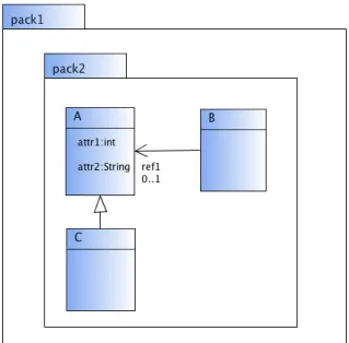
Class diagrams may contain a huge variety of different components, and therefore, the Ecore model is quite complex. To keep the example sim-ple, only a subset of components is considered, namely packages, classes, attributes, generalizations and associations. As can be seen in Figure 3.4, packages are visualized as boxes with a label at the top. Classes are visual-ized as boxes with two compartments. The upper compartment contains a label, the lower one may contain a list of attributes. Attributes are visualized
30 CHAPTER 3. RUNNING EXAMPLES as plain text, consisting of a label and a type, separated by “:”. Generaliza-tions are visualized as lines with a triangle at one end and associaGeneraliza-tions are visualized as lines that may have an arrow at no, one or two ends. Addition-ally, both ends of the line may have a label and a multiplicity. The example diagram shown consists of the packages pack1 and pack2. Furthermore, it contains the classes A, B, and C. Class A contains the attributes attr1 of type int and attr2 of type String. The diagram contains a generalization from class C to A and a unidirectional association from class B to class A
with the roleref1 and the multiplicity 0..1.
Figure 3.4: Class Diagrams
3.2.2
Meta-Model
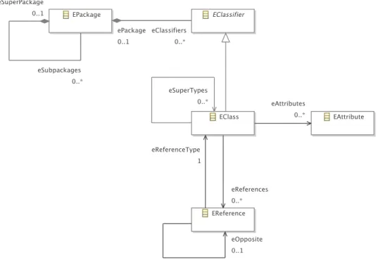
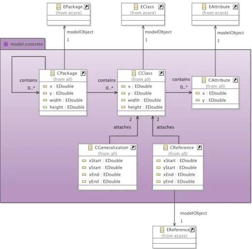
The part of the UML2 Ecore model relevant for the example diagrams pre-sented in this thesis is shown in Figure 3.5. As can be seen in Table3.1, in the meta-model, each component and each correlation between components is either represented by a class or an association in the meta-model.1
Types of attributes, as well as multiplicities and roles of associations are also represented in the meta-model, but are not shown in Figure3.5.
3.2. CLASS DIAGRAMS 31
Figure 3.5: Excerpt of the Meta-Model of Class Diagrams
Component Represented by
packages classEPackage
correlation “package in package” assoc. eSuperPackage$eSubpackages
classes classEClass
correlation “class in package” associationeClassifiers$ePackage
attributes classEAttribute
correlation “attribute of class” associationeAttributes
associations classEReference
correlation “reference from class” associationeReferences
correlation “reference to class” associationeReferenceType
bidirectional references classEReference(2x) associationeOpposite
generalizations associationeSuperTypes
32 CHAPTER 3. RUNNING EXAMPLES
3.3
GUI Forms
A somewhat different visual language are GUI forms. With this example, it will be shown that the approach is applicable in very diverse domains. A basic layout engine for this visual language may be created with the approach straightforwardly. A more sophisticated layout engine would also be feasible with this approach, but will not be described in this thesis.
3.3.1
Language
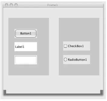
As can be seen in Figure 3.6, GUI forms may consist of frames, panels, buttons, labels, text fields, checkboxes and radio buttons. In contrast to the other components, frames and panels may contain components.
Figure 3.6: GUI Forms
Each component is visualized as some sort of rectangle. In addition, each component may have a label (called text in the meta-model), which is visu-alized as plain text. Panels and text fields do not have a label. The example diagram shown consists of a frame containing two panels. The left panel contains one button, one label and one text field (from top to bottom). The right panel contains one checkbox and one radio button (from top to bot-tom). The frame has the labelFrame1, the button Button1, the labelLabel1, the checkbox CheckBox1, and the radio button RadioButton1.
3.4. VEX DIAGRAMS 33
3.3.2
Meta-Model
The abstract syntax of the visual language is described by a meta-model, which is shown in Figure 3.7. It establishes a tree structure, and therefore mainly consists of the abstract class AbstractNode and the two abstract subclasses SingleNode and NestedNode. The structure of the meta-model follows the composite pattern: The “container” components Frame
and Panel are represented by the abstract class NestedNode, whereas the other components, such as Button or Label, are represented by the abstract class SingleNode.
Figure 3.7: Meta-Model of GUI Forms
3.4
VEX Diagrams
VEX diagrams serve as the last running example in this thesis. VEX dia-grams are a visual notation of lambda calculus [20]. This visual language has been chosen because it requires a somewhat different and complex layout behavior. Note that a slightly modified variant of this visual language is used here, which can be defined straightforwardly by the help of a meta-model: Each application is surrounded by an additional circle.
3.4.1
Language
Each VEX diagram represents a λ-expression. As can be seen in Figure3.8, VEX diagrams consist of thin circles (circles with a thin border), bold circles
34 CHAPTER 3. RUNNING EXAMPLES (circles with a bold border), lines and arrows. Aλ-expression is inductively defined. It is either a variable, an application of one λ-expression to another one or an abstraction that consists of the parameter and the abstraction body. For these three types, visual representations are defined:
• In VEX diagrams, free variables are represented by a line, which con-nects a bold circle, namely the variable, and a thin circle, which again is aλ-expression. On the left side of Figure 3.8, an example is shown: The diagram stands for the λ-expression (x), where x is the name of the variable represented by the bold circle.
• Application is visualized by a thin circle that contains two thin cir-cles. The two contained circles are located next to each other, and are connected by an arrow. The two contained circles are again two λ-expressions. The expression at the end of the arrow represents the function being applied, and the expression at the start represents the argument. In the middle of Figure 3.8, an example is shown: The di-agram stands for theλ-expression(xy). x and y are the names of the two variables that are represented by the two bold circles.
• Abstraction is visualized as a thin circle, which contains two thin circles - one attached to the inner side of its border and one located in its center. The two contained circles are connected by a line. The circle located in its center is again aλ-expression. The circle that is attached to the inner side of its border represents the parameter, and the circle that is located in its center represents the abstraction body. On the right side of Figure3.8, an example is shown: The diagram stands for the λ-expressionλx.(x).
Figure 3.9 shows two more complex examples. The first diagram consists of seven thin circles, two lines and one arrow. The diagram stands for the λ-expression λx.λy.(xy). The second diagram also consists of seven thin circles, two lines and one arrow. The diagram stands for the λ-expression (λx.x)(λy.y).
3.4.2
Meta-Model
The abstract syntax of the visual language is described by a meta-model, which is shown in Figure3.10. Aλ-expression is represented by the abstract class Expr. A λ-expression may be a free variable (class FreeVar), an application (class Appl) or an abstraction (class Abstr). Free variables are represented by the class FreeVar. The association bound references
3.4. VEX DIAGRAMS 35 the binding of the variable. Applications are represented by the class Appl. The two associations first and second reference the two λ-expressions, the application consists of. Abstractions are represented by the classAbstr. The two associations param and body reference the parameter and the λ -expression, the abstraction consists of.
Figure 3.8: VEX Diagrams: Variable Binding, Application and Abstraction
36 CHAPTER 3. RUNNING EXAMPLES
Figure 3.10: Meta-Model of VEX Diagrams
3.5
Layout Behavior
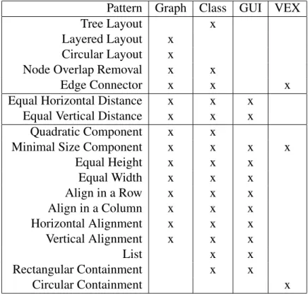
A layout pattern encapsulates certain layout behavior. It defines the layout of a set of components. This also comprises the layout of a single component. The layout patterns, which are included in editors for the four visual lan-guages introduced in the last sections, are described in the following. An overview can be seen in Table3.2. The description of all layout patterns and their encapsulated layout behavior is based on the graph editor, although not all of them are included in the graph editor.
Visual language editors, such as the ones for the languages described in the last sections, require layout patterns that are tailored to the visual language. E.g. the node overlap removal pattern is used in the graph editor and in the class diagram editor as follows: In the graph editor, nodes should not overlap. In the class diagram editor, some packages and classes should not overlap, while others should overlap, as they should be correctly nested. Nevertheless, some layout patterns can be reused straightforwardly in different editors. E.g. the edge connector pattern is used in the graph editor and in the class diagram editor as follows: In the graph editor, edges should stay attached to their corresponding nodes, and in the class diagram editor, associations and generalizations should stay attached to their corresponding classes.
3.5. LAYOUT BEHAVIOR 37 Pattern Graph Class GUI VEX
Tree Layout x Layered Layout x
Circular Layout x
Node Overlap Removal x x
Edge Connector x x x
Equal Horizontal Distance x x x Equal Vertical Distance x x x
Quadratic Component x x
Minimal Size Component x x x x Equal Height x x x Equal Width x x x Align in a Row x x x Align in a Column x x x Horizontal Alignment x x x Vertical Alignment x x x List x x Rectangular Containment x x Circular Containment x
Table 3.2: Patterns in Diagram Editors
in different variants. For instance, a spacing between the container and the contained element can be defined for the rectangular containment pattern. Details about variants of layout patterns, and about the integration of pat-terns into the editors described in the last sections will be given in Chapter8.
3.5.1
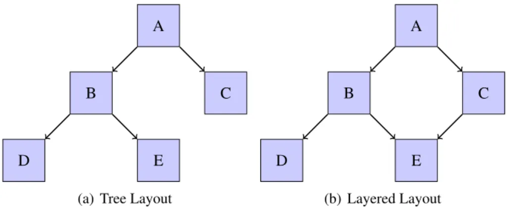
Tree Layout
The first pattern presented, the tree layout pattern, establishes a tree struc-ture in the graph. To do so, it applies a standard graph drawing algorithm, e.g. one of the tree layout algorithms that are included in the yFiles library [117]. The pattern is restricted to trees, and cannot be applied to general graphs. Figure 3.11(a)shows a diagram after applying the pattern.
3.5.2
Layered Layout
The layered layout pattern establishes a layered structure in the graph. To do so, it applies a standard graph drawing algorithm, e.g. one of the hierarchical layout algorithms that are included in the yFiles library [117]. The pattern is quite similar to the tree layout pattern in a sense that nodes are positioned
38 CHAPTER 3. RUNNING EXAMPLES on one or more horizontal or vertical lines, namely the layers. In contrast to the tree layout pattern, it may be applied to arbitrary graphs. Hence, it is (more or less) a generalized version of the tree layout pattern. Figure3.11(b) shows a diagram after applying the layered layout pattern.
A
B C
D E
(a) Tree Layout
A
B C
D E
(b) Layered Layout
Figure 3.11: Tree Layout and Layered Layout
3.5.3
Circular Layout
The circular layout pattern is also applicable to arbitrary graphs, and estab-lishes a circular structure in the graph. This means that nodes are positioned on one or more circles. To do so, it applies a standard graph drawing algo-rithm, e.g. one of the circular layout algorithms that are included in the yFiles library [117]. Figure 3.12(a) shows a diagram after applying the cir-cular layout pattern.
3.5.4
Node Overlap Removal
The node overlap removal pattern is a somewhat different layout pattern. It is applied to nodes only and eliminates all node overlaps. The size and the shape of a component are crucial and need to be taken into account. Node overlap removal is usually achieved by pulling nodes apart. To do so, it applies a force-directed layout algorithm, e.g. one that is included in the Jung library [90]. Figure 3.12(b) shows a diagram after applying the node overlap removal pattern.
3.5.5
Edge Connector
The edge connector pattern ensures that edges are correctly connected to nodes. Figure3.13 shows a diagram after applying the pattern.
3.5. LAYOUT BEHAVIOR 39 A B C D E F G
(a) Circular Layout
A B
C D
E
(b) Node Overlap Removal
Figure 3.12: Circular Layout and Node Overlap Removal
A B
C D
E
Figure 3.13: Edge Connector
3.5.6
Equal Horizontal Distance
The equal horizontal distance pattern is applied to nodes, and establishes an equal horizontal distance between them. One characteristic of this layout pattern is that the horizontal ordering of nodes is preserved. Figure 3.14(a) shows a diagram after applying the equal horizontal distance pattern.
3.5.7
Equal Vertical Distance
Analogously, the equal vertical distance pattern establishes an equal vertical distance between nodes. One characteristic of this pattern is that the vertical ordering of nodes is preserved. Figure3.14(b)shows a diagram after applying the equal vertical distance pattern.