The Design, Fabrication, and Magnetic Actuation of a
Microactuator to Accomplish Propulsion and Large
Deflection in Viscous and Elastic Environments
Briana Lee Fiser
A dissertation submitted to the faculty of the University of North Carolina at Chapel Hill in partial fulfillment of the requirements for the degree of Doctor of Philosophy
in the Department of Physics and Astronomy.
Chapel Hill 2012
Approved by:
Dr. Richard Superfine
Dr. Michael Falvo
Dr. Greg Forest
Dr. Fabian Heitsch
c
Abstract
BRIANA LEE FISER: The Design, Fabrication, and Magnetic Actuation of a Microactuator to Accomplish Propulsion and Large Deflection in Viscous and Elastic
Environments
(Under the direction of Dr. Richard Superfine)
Biomimetics is the study of the structure and function of biological organisms, proper-ties, or substances to inform or inspire the creation of artificial mimics. Nature’s evolution-arily evolved answers to its own obstacles can become great solutions to our problems in the fields of physics, materials science, and engineering. The field of biomimetics has both led to technological advances and utilized biomimetic systems to glean knowledge about their biological inspirations. I have developed a single biomimetic system which both mimics a biological system well enough to inform biology and is capable of advancing technology. This biomimetic system is composed of novel core-shell microrods that closely mimic the size of biological cilia and generate fluid transport in both viscous and viscoelastic flu-ids. Complex biological processes such as the determination of left-right asymmetry in the vertebrate embryonic node and mucociliary clearance in the lung are dependent on the successful transport of fluids, both buffer-like and viscoelastic. A biomimetic system such
Acknowledgments
This work could not have been completed without the knowledge and support of the group of faculty and students with whom I have worked in the fishbowl of Chapman Hall. My advisor, Rich Superfine, has taught me several of the most valuable lessons learned at Chapel Hill, one of which is how to always have fun with science. His energy and excitement about everything science is encouraging, and I hope to always have that same exuberance. Mike Falvo and Sean Washburn have also been great advisors during my time with the group, always willing to take a few minutes to answer questions or talk about data analysis. Also, thank you to Greg Forest for always taking an interest in the biomimetic systems I have developed and being positive in every interaction we have had.
As for the students, I will never work with a better group - Jerome Carpenter, Lamar Mair, Vinay Swaminathan, Ricky Spero, Kwan Skinner, and everyone else in NSRG. The sense of community and the eagerness of all of us to help each other and work together made it a wonderful place to go to work every day for the last five years. Jeremy Cribb was a lifesaver when it came to teaching me Matlab and how to code the first summer I joined the lab. Ben Evans and Adam Shields (also NSRGers) were my cilia co-conspirators. Ben spent his last summer with the group training me how to take his place (a difficult feat that
Table of Contents
List of Tables . . . xi
List of Figures . . . xii
List of Abbreviations . . . xvi
List of Symbols . . . xviii
1 Introduction . . . 1
1.1 Organization of the Thesis . . . 7
2 The Biological Cilium . . . 11
2.1 Bronchial epithelial cilia . . . 13
2.2 Vertebrate embryonic nodal cilia . . . 16
3 Designing the Ideal Actuator . . . 20
3.1 Current microactuators for use as artificial cilia . . . 22
3.1.1 Actuation with electrostatics . . . 23
3.1.2 Actuation with UV-Visible light . . . 24
3.1.3 Actuation with a piezo stage . . . 25
3.2 Cantilevered beams as damped, driven harmonic oscillators . . . 28
3.2.1 The damped and driven harmonic oscillator . . . 32
3.3 Figure of Merit for Actuators . . . 39
3.3.1 Energy minimization model . . . 40
3.4 Torque on a Rod . . . 51
3.5 Ground and Lateral Collapse . . . 55
4 Materials and Fabrication . . . 58
4.1 Template Fabrication . . . 59
4.2 Magnetic Composite Materials . . . 61
4.2.1 Maghemite-polymer composite material . . . 65
4.2.2 Magnetite-polymer complexed material . . . 68
4.3 Core-shell Materials . . . 72
4.3.1 Fabrication of core-shell structures . . . 76
4.3.2 Energy Dispersive X-ray analysis . . . 83
4.3.3 Applied field dependence . . . 85
5 Magnetic Actuation . . . 88
5.1 Responsiveness of composite and core-shell actuators . . . 91
5.1.1 The power of the core-shell structure . . . 95
5.2 Mimicking the biological cilia beat shape . . . 96
5.2.1 The linear beat . . . 98
5.2.2 The tilted conical beat . . . 101
6 Fluid Transport in Aqueous and Viscoelastic Fluids . . . 107
6.1 Review of microscale hydrodynamics . . . 110
6.1.1 Dimensionless Numbers . . . 110
6.1.2 Navier-Stokes equation . . . 116
6.1.3 Navier-Stokes equation and purely viscous stresses . . . 119
6.1.4 Stokes’ 1st and 2nd problems . . . 122
6.1.5 Modified Stokes’ 2nd problem . . . 127
6.2 Fluid Transport in Aqueous Fluids . . . 134
6.2.1 Flow velocity dependence on cilia beat frequency . . . 135
6.2.2 Two regimes of flow . . . 137
6.2.3 Implications for biology and technology . . . 145
6.3 Fluid transport in viscoelastic fluids . . . 147
6.3.1 The viscoelastic fluid agarose . . . 150
6.3.2 Flow velocity dependence on biomimetic cilia beat frequency . . . . 155
6.3.3 Directed transport and the flow profile . . . 158
6.3.4 Implications for biology and technology . . . 165
7 Core-shell Biomimetic Cilia as a Rheometer . . . 171
7.1 Core-shell actuators for use as microrheometers . . . 173
7.2 Coagulation cascade and coagulopathies . . . 177
7.2.1 Current measurement techniques . . . 181
7.3 Measuring clotting times with core-shell cilia . . . 187
A Blood coagulation . . . 200
List of Tables
3.1 Critical rod aspect ratios for ground and lateral collapse . . . 56
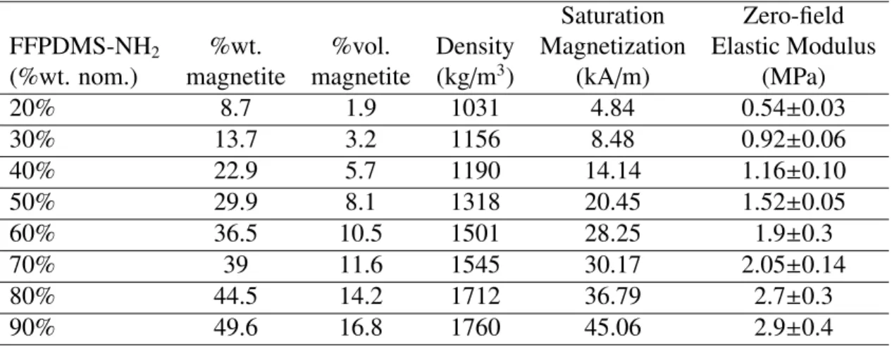
4.1 Properties of various dilutions of FFPDMS-NH2in PDMS-NH2 . . . 70
4.2 Characteristics of sputtered metals . . . 79
6.1 Characteristic scales of biological and biomimetic cilia . . . 113
6.2 Viscous stress tensors (Macosko, 1994) . . . 118
7.1 Onset of plasma clotting times . . . 195
List of Figures
2.1 From Fauci et al. (2006). Diagram of 9+2 cilium axoneme . . . 12
2.2 Lung schematic and SEM images of human airway cilia . . . 14
2.3 SEM images of mouse embryonic nodal cilia . . . 17
3.1 From van Oosten et al. (2009). Liquid crystalline artificial cilia . . . 25
3.2 From Vilfan et al. (2009). Magnetic artificial cilia . . . 28
3.3 Radius of curvature of rods . . . 30
3.4 Cantilever amplitude dependence on frequency in various viscosities . . . . 38
3.5 From Evans et al. (2007). Energy minimization model parameters . . . 41
3.6 Diagram of a core-shell rod . . . 45
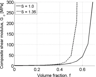
3.7 Mooney equation - Composite shear modulus versus volume fraction . . . . 47
3.8 Maximum bend angle for composite and core-shell rods . . . 50
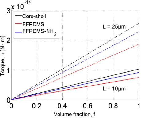
3.9 Torque of composite and core-shell materials . . . 53
3.10 Maximum bend angle and torque for core-shell cilia . . . 54
3.11 SEM images of collapsed microrods . . . 57
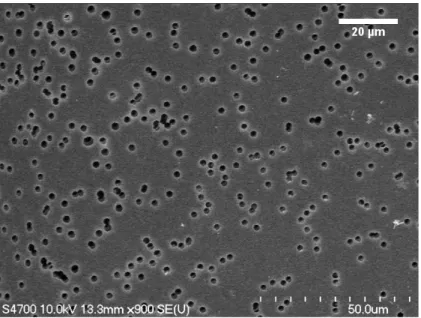
4.1 SEM image of a polycarbonate track-etched membrane . . . 59
4.2 PCTE membrane pore diameter as a function of etch time . . . 60
4.3 Magnetization curves for maghemite and magnetite . . . 64
4.4 From Evans et al. (2007). FFPDMS cilia fabrication diagram . . . 66
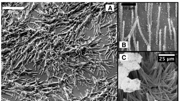
4.5 SEM images of FFPDMS biomimetic cilia . . . 67
4.7 Homogeneity of FFPDMS-NH2. . . 71
4.8 SEM images of FFPDMS-NH2 biomimetic cilia . . . 72
4.9 Core-shell actuators in literature . . . 75
4.10 Electrodeposition set-up . . . 77
4.11 Au/Pd layer on PCTE membrane . . . 78
4.12 SEM image of electrodeposited Ni tube . . . 80
4.13 Core-shell cilia fabrication diagram . . . 82
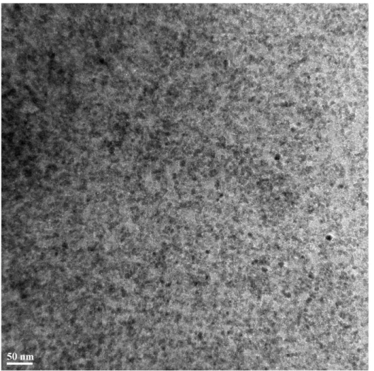
4.14 SEM image of core-shell biomimetic cilia . . . 83
4.15 EDS scan of core-shell biomimetic cilium . . . 85
4.16 Magnetization curve for core-shell cilia . . . 86
4.17 From Encinas-Oropesa et al. (2009). Ni nanowire magnetization curves . . 87
5.1 Magnetic field as a function of distance from magnet . . . 90
5.2 Minimum intensity projection of amplitude of FFPDMS cilia . . . 92
5.3 Minimum intensity projection of amplitude of core-shell cilia . . . 93
5.4 Minimum intensity projection of amplitude of core-shell cilia . . . 94
5.5 Amplitude vs. frequency for core-shell and FFPDMS actuators in PBS . . . 95
5.6 Minimum intensity projection of cilium bend greater than 90◦ . . . 96
5.7 Biological cilia beat shapes . . . 97
5.8 Linear beat shape set-ups . . . 98
5.9 Illustration of cilium performing linear beat . . . 100
5.10 Diagram of magnetic actuation set up for the tilted conical beat . . . 102
5.12 Measuring the tilt and bend angles of a biomimetic cilium . . . 104
6.1 Poiseuille and Couette flow profiles . . . 121
6.2 Stokes’ 2nd problem in a viscous fluid . . . 126
6.3 Modified Stokes’ 2nd problem with a viscous fluid . . . 128
6.4 Linear Maxwell model schematic . . . 130
6.5 Modified Stokes’ 2nd problem with a viscoelastic fluid . . . 133
6.6 Core-shell cilia-driven flow velocity vs. time in an aqueous fluid . . . 135
6.7 Core-shell cilia-driven flow velocity vs. frequency in PBS . . . 136
6.8 Biomimetic cilia-driven flow regimes in aqueous fluids . . . 139
6.9 Flow profiles for FFPDMS and core-shell cilia . . . 140
6.10 PC fit to embryonic nodal cilia-driven flow . . . 142
6.11 Relative diffusivity as a function of height for FFPDMS cilia . . . 144
6.12 Apparent viscosity vs. shear rate for HBE mucus and agarose . . . 151
6.13 Stress sweeps in 0.1% agarose . . . 153
6.14 Loss tangent for 0.1% agarose . . . 154
6.15 Average flow velocity vs. beat frequency for core-shell cilia . . . 156
6.16 Linear fit to flow velocity vs. beat frequency atz= 20µm . . . 157
6.17 Biomimetic cilia-driven flow profile in 0.1% agarose at 16 Hz . . . 160
6.18 Biomimetic cilia-driven flow profile in 0.1% agarose with model fits . . . . 161
6.19 Biomimetic cilia-driven flow profile in 0.1% agarose at 0.65 Hz . . . 163
6.20 Temperature dependent cilia-driven tracer paths in 0.25% agarose . . . 164
6.22 From Boucher et al. (2004). Micrograph of a human bronchial culture . . . 167
6.23 Cilia amplitude vs. magnetic field in viscous and viscoelastic fluids . . . 170
7.1 Cantilever amplitude vs. frequency in various fluid viscosities . . . 176
7.2 Overview of the coagulation cascade . . . 178
7.3 From Hess et al. (2008). Trauma induced coagulopathy mechanisms . . . . 180
7.4 From Johansson et al. (2009). TEG and ROTEM measurement curves . . . 183
7.5 From Johansson et al. (2009). Various TEG traces . . . 185
7.6 Handheld POC device with core-shell rods . . . 187
7.7 Core-shell cilia in a Level 1 plasma clot . . . 189
7.8 Intensity traces for core-shell cilia in plasma clots, Levels 1 and 2 . . . 190
7.9 Mechanical and turbidity measurements in plasma clots, Levels 1 and 2 . . 194
7.10 Long time amplitude of core-shell cilia in Level 1 plasma clot . . . 195
List of Abbreviations
AAO anodic aluminum oxide
APTT activated partial thromboplastin time
ASL airway surface liquid
CF cystic fibrosis
CPD critical point dry
DCM dichloromethane
De Deborah number
EDS Energy Dispersive X-ray Spectroscopy
FFPDMS ferrofluid-poly(dimethylsiloxane)
FFPDMS-NH2ferrofluid-aminopropylmethysiloxane-dimethylsiloxane
GUI graphical user interface
HBE Human Bronchial Epithelial
MSD mean square displacement
NaOH sodium hydroxide
NVP nodal vesicular parcel
PBS Dulbecco’s Phosphate Buffered Saline
PCD primary ciliary dyskinesia
PCTE polycarbonate track-etched
PCL periciliary layer
PDMS poly(dimethylsiloxane)
PEG poly(ethylene) glycol
POC point of care
PT prothrombin time
PVP Poly(vinylpyrrolidone)
Re Reynolds number
ROTEM rotational thromboelastometry
TEG thromboelastography
TIC trauma induced coagulopathy
TF tissue factor
tPA tissue plasminogen activator
VHA viscoelastic haemostatic assay
List of Symbols
α angle of magnetic moment of rod
A cross sectional area
b damping coefficient
�
B applied magnetic field
�
BT total applied magnetic field
∇�B magnetic field gradient δ phase angle
d diameter
η dynamic fluid viscosity
E elastic modulus
f magnetic loading, volume fraction
fCS volume fraction of core-shell cilia
F0 driving force magnitude γ damping factor
G� storage modulus
G�� loss modulus
I second moment of inertia
κ curvature
k spring constant
l,L length
LPDMS length of core-shell pure PDMS segment
m mass
�
m magnetic moment
�
M magnetization per unit volume
µ0 permeability of free space ν kinematic fluid viscosity φ bend angle of a rod ρ density
ψ� angle of magnetic field gradient
r radius
R,R(s) radius of curvature τ,N torque
t Ni tube thickness
UA(B�A) energy of applied magnetic field
UB magnetic energy
UE elastic energy
UI(�BI) internal energy of the rod
UN(B�N) magnetic field energy felt from neighboring rods
v velocity
V volume
ω angular frequency
Chapter 1
Introduction
Biomimetics is the study of the structure and function of biological organisms, proper-ties, or substances to inform or inspire the creation of artificial mimics. The word was first coined by Otto Schmitt whose doctoral research in 1957 comprised the development of a device which mimicked a nerve’s electrical actions (Bhushan, 2009). Schmitt was heard using the term ‘biomimetics’ as a substitute for ‘bionics’ when discussing the utilization of insights obtained from the study of biological phenomenon to develop unique systems which mimic that phenomenon (Vincent et al., 2006). The creation of biomimetic devices or platforms may be fueled by the desire for new technology or a simpler, more elegant an-swer to a common problem. Nature’s evolutionarily evolved anan-swers to its own obstacles can become great solutions to our problems in the fields of physics, materials science, and engineering.
each spine. After several engineering attempts with different materials, nylon velcro was
born.
A second example is the lotus leaf, with its superhydrophobicity, a property which has been studied in great detail and applied to various commercial products. A surface is con-sidered hydrophobic if the static contact angle between the surface and a water droplet is greater than 90◦ and superhydrophobic if the contact angle is greater than 150◦. The lotus
leaf’s structure, at the microscale, comprises bumps approximately 4 µm in size spread
across the leaf’s surface. The presence of these structures along with a hydrophobic wax-like coating, repels water and aids in the self-cleaning of the leaf. The properties of super-hydrophobicity and self-cleaning are highly desirable in many instances, most especially in applications where biofouling, the accumulation of microorganisms or plants on a surface, is a hindrance. Biofouling on large ships or boats increases the vessel’s drag in the water; building a vessel with an antifouling, or self-cleaning, surface would reduce drag, creating more fuel efficient vessels. Other applications which have been commercially produced are
self-cleaning paints, windows, and roofing tiles (Bhushan, 2009).
this system to both biology and technology which is the subject of this dissertation.
My biomimetic system is inspired by and seeks to inspire an appendage which is ubiq-uitous in nature – the biological cilium. Biological cilia are present in nearly every organ in vertebrates and are responsible for a multitude of different tasks including cell motility,
fluid propulsion, mechanical sensing, and chemosensation, a task only recently attributed to cilia. In the last two years, ciliated cells in the human airway were found to express bitter taste receptors which localized along the length of cilia. The introduction of a bitter compound increased ciliary beat frequency thereby confirming the ability of airway cilia to sense noxious substances upon entrance into the lungs (Shah et al., 2009).
Biological cilia can be divided into two large classes: motile and non-motile. The dif-ference between motile and non-motile cilia is the presence or absence of the motor protein axonemal dynein. A cilium’s structure, also called the axoneme, may be either ‘9+0’ or
‘9+2’, the first number indicating the number of microtubular doublets around the
situs inversus, infertility, hydrocephalus, and death (Afzelius, 2004). Non-motile cilia are typically responsible for sensing applications, including smell, light perception, and flow sensing within the kidneys. If non-motile cilia are not formed correctly or incapable of performing their various functions, the consequences could include anosmia, blindness, or polycystic kidney disease, a disease which includes the development of large cysts on the kidneys (Pan et al., 2005; Satir and Christensen, 2008).
Part of my research has focused on the design, fabrication, magnetic actuation, and application of a biomimetic cilia system to develop a deeper understanding of motile bi-ological cilia responsible for two functions in particular: (i) mucociliary clearance in the lung, and (ii) the development of left-right asymmetry during vertebrate embryogenesis. Both of these biological functions require motile cilia to propel fluid flow in a particular direction. For the lung, viscoelastic mucus must be propelled up and out of the lung by beating cilia to clear our lungs of pathogens. In the vertebrate embryo, a Newtonian fluid must be transported from the right side of the embryo to the left by beating cilia to estab-lish the asymmetry of the embryo. The benefits of utilizing a biomimetic system to ask the questions which biology is currently asking are enormous. Biomimetic systems allow for the exploration of the impact of individual parameters on the system as a whole. How does altering the beat frequency affect fluid transport? How does a different fluid restrict or
en-hance the mobility of a cilium or alter the cilium’s ability to transport that fluid? How does the beat shape of an array of cilia affect the velocity of transport? All of these questions can
of cilia with dimensions that are a true mimic of biological cilia is integral to answering these questions and more as fluid at the microscale is distinctly different from fluid at the
macroscale.
The system I have designed consists of an array of individual rods that are ten microns tall and 0.55 µm in diameter, spaced approximately 7-10µm apart. These rods are both
flexible and magnetic, capable of deforming in response to an applied magnetic field. They are capable of performing various beat shapes, as all biological cilia do not beat in the same manner. Both the flexibility and magnetic property of a biomimetic cilium arises from the combination of materials utilized in the fabrication process. The use of a soft, elastic polymer poly(dimethylsiloxane) supplies biomimetic cilia with flexibility, and in-troducing a magnetic material, such as nickel or iron oxide, provides a convenient method of controlling the cilia array through the use of a magnetic field. By fabricating a novel core-shell structure, such that a single cilium consists of a polymer core with a nickel shell surrounding its upper portion, I have created an array of highly responsive rods capable of bending such that their tips contact the substrate to which they are attached. The highly responsive nature of these core-shell biomimetic cilia allows me to explore and inform the biological questions I posed previously, as even within fluids as viscous and elastic as mu-cus and sputum, I am able to actuate biomimetic cilia arrays, both detecting and measuring biomimetic cilia amplitude and the resulting cilia-driven fluid flow.
viscous fluids lends itself to a new application, one in which the motion of a single cilium is employed to monitor changes in the viscosity or elasticity of the fluid in which it sits. More specifically, this system, as an array of rods, shows potential as a technological advance in the world of point-of-care devices for measuring the coagulation of blood clots.
Blood clots form to stem the flow of blood from damaged blood vessels. If clotting occurs too slowly, increased bleeding or hemorrhaging may occur, and conversely, if clot-ting occurs too quickly, patients are at an increased risk of developing blood clots, which could impair the flow of blood within the veins. These two possibilities are only two in an entire class of bleeding or clotting disorders known as coagulopathies. Either of these scenarios may result in death as coagulopathies are a leading cause of morbidity in the world (Hess et al., 2008). One in four trauma patients admitted to the emergency room, which account for 90% of emergency room admissions, is admitted with a coagulopathy and has a corresponding four fold mortality increase (Hess et al., 2008; Niles et al., 2008). By monitoring the change in amplitude as a blood clot forms, biomimetic cilia arrays are capable of measuring the clotting time for blood, and as I will discuss, are more sensitive to the onset of blood clotting than traditional coagulation assays.
Statistics such as these indicate the necessity of diagnostic tests with the ability to rapidly assess clot-related parameters for the treatment of patients suffering from trauma.
Several such diagnostic tests are currently on the commercial market; however, these tests are not packaged in a portable way such that they may be used at the location of the pa-tient directly after injury is suffered. Immediate diagnosis of a coagulopathy is necessary
Devices capable of transport to the site of the patient are called point-of-care devices, and no such point-of-care devices currently exist for monitoring blood coagulation. Due to the nature of the fabrication process for my biomimetic cilia arrays, the size of the array can very easily be varied from one square millimeter to sheets as large as the size of the equip-ment utilized in the fabrication process. As such, a device can be constructed to fit in the palm of one’s hand to maximize transportability of the diagnostic test.
1.1 Organization of the Thesis
I begin this thesis with a chapter on the biological cilium within the context of mucocil-iary clearance and embryogenesis. The biological cilium is an amazing structure, and as the majority of my work has been designing and fabricating a biomimetic system to better understand biological cilia, I will start by giving the reader a more thorough understanding of the inspiration for this work. In the third chapter, I will discuss the design parameters that are considered when fabricating an array of rods, as the rods must be both highly flexi-ble and highly magnetic to maximize their response to an applied magnetic field in fluids as viscoelastic as mucus and sputum. Increasing magnetic content to increase responsiveness typically causes a corresponding increase in stiffness such that the rod becomes less
respon-sive. Devising the core-shell structure, as I describe in Fiser et al., a prepared manuscript detailing the design and fabrication of these biomimetic cilia, is a smart method to sepa-rate, as much as possible, the contributions of the magnetic content to the stiffness of the
rod (Fiser et al., 2012).
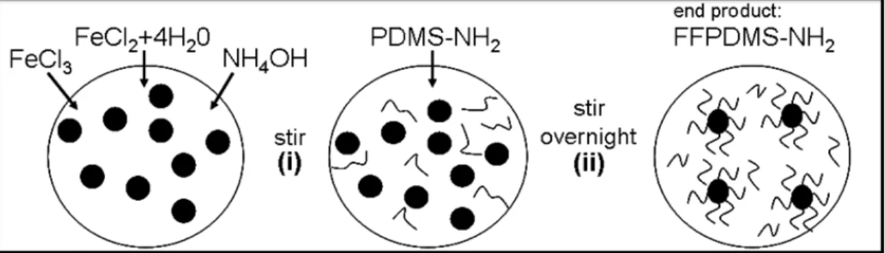
dif-ferent types of materials: maghemite ferrofluid-poly(dimethysiloxane) (FFPDMS), mag-netite ferrofluid-poly(dimethylsiloxane) (FFPDMS-NH2), and poly(dimethylsiloxane) core
- nickel shell. The first two materials are suspensions of magnetic nanoparticles within a polymer matrix, and the third is a core-shell structure. FFPDMS cilia were developed prior to my joining the lab by Ben Evans and Adam Shields and are discussed in Evans et al., 2007. However, these cilia have been utilized in some experiments discussed in both this thesis and the publication Shields, Fiser, et al., 2010. In addition, the fabrication process for FFPDMS cilia is similar to the process I have devised for FFPDMS-NH2and core-shell
biomimetic cilia.
A second material utilized in the fabrication of biomimetic cilia is FFPDMS-NH2,
though these cilia were not used in experiments. The composite material is an improvement upon FFPDMS; rather than a simple suspension of nanoparticles within a polymer matrix, individual nanoparticles in FFPDMS-NH2 have polymer strands adsorbed onto their
sur-faces, a process described in Evans, Fiser, et al., 2012. This adsorption of polymer onto nanoparticle prevents aggregation, thereby allowing for a slightly higher magnetic content within each cilium without an appreciable increase in stiffness, generating larger rod
re-sponses. The third material, poly(dimethylsiloxane) core - nickel shell, is an improvement on both FFPDMS and FFPDMS-NH2, as the polymer and magnetic material are separate
and thus an increase in magnetic content has little effect on the flexibility of the cilium.
After detailing the fabrication process for biomimetic cilia, Chapter 5 explores various techniques for cilia actuation. The beat shape employed to address the biological questions I have posed in this Introduction (which will be addressed in Chapter 6) is called the ‘tilted conical beat’ and is performed by vertebrate nodal embryonic cilia. The beat shape em-ployed in the new technology capable of measuring viscoelastic fluid properties and blood coagulation (which will be addressed in Chapter 7) is called the ‘linear’ beat and is a beat shape performed by lung epithelial cilia.
Before presenting the results and discussion for biomimetic cilia-driven fluid flow, in the beginning of Chapter 6, I will provide a brief overview of fluid flow at the microscale and discuss the concept of the Reynolds number and the fundamental equation of motion for fluids, the Navier-Stokes equation. Various solutions to the Navier-Stokes equation for both purely viscous and viscoelastic fluids will be examined as the solutions are utilized to describe fluid motion driven by an array of biomimetic cilia. After the introduction to microhydrodynamics, Chapter 6 is broken down into two further parts: aqueous fluid transport and viscoelastic fluid transport. Section 6.2 describes the fluid flow above and below biomimetic cilia tips in a purely viscous fluid as well as the implications I draw from these results for both biology and technology. For biomimetic cilia-driven viscoelastic fluid flow, Section 6.3 considers the viscoelastic fluid agarose, which is used in experiments, the comparison of flow between a viscous and viscoelastic fluid, and again, the implications of these results for biology and technology.
Chapter 2
The Biological Cilium
Biological cilia can be motile or non-motile, a determination made by the presence or absence of axonemal dynein motor proteins which allow them to bend. The biological cilia I seek to mimic, those responsible for mucociliary clearance in the lung and the de-velopment of left-right asymmetry during vertebrate embryogenesis, are both motile and possess axonemal dyneins; however, each cilium’s internal structure is distinctly different.
The internal structure of a cilium is called the axoneme, and it stems from the basal body, a structure anchored to the cell’s surface by the basal foot. The delineation for the different
internal structures is based on whether or not the cilium is a ‘9+2’ structure or a ‘9+0’
struc-ture. Initially only 9+2 cilia were considered motile and 9+0 cilia, or primary cilia, were
assumed to be non-motile; however, with the discovery of nodal embryonic cilia, which are motile and have a 9+0 ultrastructure, cilia are more often described as motile or non-motile
than ‘9+0’ or ‘9+2’ (Satir and Christensen, 2008). Both cilium types consist of nine outer
doublet microtubules that extend along the length of the cilium. In addition to these nine doublets, the 9+2 cilium contains two microtubule singlets in the axoneme’s center. Figure
2.1 depicts a schematic of the cross-section of a 9+2 cilium’s axoneme (Fauci and Dillon,
Figure 2.1: Reprinted from Fauci et al. (2006). Schematic of the axoneme for a 9+2
cilium. The significant difference between 9+2 and 9+0 cilia is the presence of the central
microtubules (Fauci and Dillon, 2006).
The nine outer microtubule doublets are connected by nexin links, preventing them from exhibiting motion with respect to a microtubule neighbor. In addition to these links, dynein arms are present on each microtubule doublet. The motion of these dynein arms is driven by ATP, which causes them to walk on the surface of a neighboring microtubule. This walking produces the bending motion of a cilium. Four doublets on one side operate to produce the effective stroke, and five doublets on the other side operate to produce the
recovery stroke. The effective stroke occurs in the direction of fluid motion, and during
the recovery stroke, the cilium is typically close to the cell surface. Dynein arms come in two sets: the inner dynein arms which are thought to control the beat shape and the outer dynein arms which are thought to control the beat frequency (Fauci and Dillon, 2006; Satir and Christensen, 2008).
In the 9+2 axoneme, the outer nine microtubule doublets are linked to the central pair
such as those found in the lung and 9+0 cilia such as those found in the embryonic node
is markedly different. The radial spokes in 9+2 cilia serve to reinforce the structure of the
cilium and likely contribute to the planar shape of the 9+2 beat. In 9+0 cilia, the lack of
microtubules in the central region likely contributes to the conical shape of the 9+0 beat.
2.1 Bronchial epithelial cilia
Bronchial epithelial cilia, with a 9+2 ultrastructure, are primarily responsible for
filter-ing and removfilter-ing pathogens from the lung in order to prevent infection and illness. This complex process of clearing the lung is called mucociliary clearance. Lining the lung’s conducting airways are cilia and the airway surface liquid (ASL), a layered fluid composed of a watery-like periciliary layer (PCL) and the viscoelastic fluid mucus, as illustrated in Figure 2.2A. The side of the mucus layer not in contact with the PCL is exposed to air. Human bronchial epithelial cilia are typically 7µm tall, 250 nm in diameter, and grow in
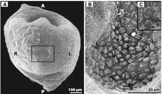
patches on the apical surface of the cell, as shown in Figure 2.2B and C. The PCL in which cilia sit is also approximately 7µm high. In a healthy system, mucus, which has been
A B C
Figure 2.2: (A) Reprinted from Boucher et al. (2004). Schematic of cells in the lung. The cilia sit in a layer of fluid called the PCL, above which is the mucus layer (Boucher, 2004). (B-C) Scanning electron micrographs of human airway cilia, which are typically 7µm tall and 250 nm in diameter. Lung epithelial cilia grow in patches on the apical cell surface.
Healthy airway cilia beat with an effective stroke, in which a cilium straightens
verti-cally, followed by a recovery stroke, in which bending occurs and the cilium remains near the cell surface. This beat is almost entirely planar, and the effective stroke occurs in the
direction of fluid motion, driving the fluid upward and out of the lung. This asymmetry in the cilium’s beat shape is critical for the net transport of mucus out of the lung, as the cilia exist in a low Reynolds number environment where inertia plays no role.
The mechanism of this transport, however, is still poorly understood. There remain many open questions concerning interactions between cilia and the mucus layer. When cilia come into contact with the mucus layer during the effective stroke, what mechanical
interactions occur? The mucus layer in the upper airways is thought to begin at the cilia tips and extend 15-20 µm above (Boucher, 2004). Within the airways, does this entire
layer move? Must the entire layer of mucus move to clear our lungs of pathogens? My biomimetic cilia system is poised to answer these questions.
process, two of which are cystic fibrosis (CF) and primary ciliary dyskinesia (PCD). CF is essentially a disease caused by the failure of the mucociliary process, as patients are born with healthy lungs, but over the years acquire bacterial infections within their airways. Nor-mal functioning of the mucociliary process is dependent on a number of factors including regulation of the PCL height. Without the PCL, cilia are immersed in mucus and become inefficient at clearing mucus from the lungs. Patients with CF suffer from a depleted PCL,
resulting in a much-thickened mucus, and the mechanical process of mucociliary clearance no longer works effectively to clear the lungs of pathogens (Boucher, 2004). Biomimetic
cilia immersed in a viscoelastic fluid such that the fluid fills the space throughout and above the cilia layer (an experiment I discuss in Section 6.3) could contribute to our understanding of this clearance inefficiency. In this experiment, the rate of net transport of the viscoelastic
fluid was determined to be 1/12 that of buffer, indicating a lack of clearance. Before
in-terpreting and applying results such as these constructively to the biological system, more experiments would be needed to further elucidate the mechanical interaction between the cilium and the viscoelastic fluid as a function of viscoelasticity. In addition, as transport rates may vary in the presence of a layered fluid, it would be informative to investigate the effect of different layer thicknesses on transport. Again, the biomimetic cilia system is
poised to contribute insight to these biological phenomena.
A second disorder that hampers mucociliary clearance is primary ciliary dyskinesia, which affects the assembly or function of axonemal dynein, leading to a change in the
including male infertility and hydrocephalus (Satir and Christensen, 2008).
The linear beat shape employed by airway cilia is mimicked by biomimetic cilia with the use of a passing permanent magnet (described in Section 5.2.1), as biomimetic cilia are magnetic and seek to align themselves with the direction of an applied magnetic field. However, they are currently incapable of accurately mimicking the complexity of the beat shape exhibited by biological airway cilia; biomimetic cilia act as stiffprojections from the
substrate.
2.2 Vertebrate embryonic nodal cilia
The second biological cilium mimicked by biomimetic cilia is the vertebrate embryonic nodal cilium. The human body has three different axes − the anterior-posterior axis, the
dorsal-ventral axis, and the left-right axis − which are determined during the course of embryogenesis. The anterior-posterior and dorsal-ventral axes are determined randomly, though perpendicular to one another. The left-right axis is the final axis to be determined, and it must be determined with respect to the other two axes. Vertebrate embryonic nodal cilia, with a 9+0 ultrastructure, play a vital role in determining this left-right axis, which
refer to the left and right sides of a vertebrate embryo, during embryogenesis (Hirokawa et al., 2009). They produce a leftward flow of extraembryonic fluid in the ventral embryonic node which is critical for proper determination of the left-right axis of the embryo. A conservation of this leftward flow has been shown among multiple species, including the rabbit, medakafish, and mouse (Okada et al., 2005).
ventral side of the embryo. Figure 2.3 depicts the embryonic node and nodal cilia of a mouse. The node comprises a number of cells, each with a single cilium projecting from its surface. These nodal cilia are approximately 5µm long and 300 nm in diameter. Because
their ultrastructure is 9+0, they lack a central pair of microtubules and thus do not employ
the planar beat exhibited by 9+2 cilia. Embryonic nodal cilia employ the ‘the tilted conical
beat’, a conical beat that orbits about a tilted axis, typically tilted 40◦ from the vertical
(Hirokawa et al., 2009). The cilium is most efficient at propelling fluid at the top of its beat,
as when the cilium passes near the cell surface, a no-slip boundary condition is in play. In theoretical treatments, this tilted axis of rotation is critical to the production of directional flow, as in low Reynolds number environments where viscous forces dominate over inertial forces, asymmetry is critical in producing net displacement (Cartwright et al., 2007; Smith et al., 2008).
A B C
Figure 2.3: Reprinted from Hirokawa et al. (2009). Scanning electron micrographs of a mouse embryo. (A) View of the ventral side of a mouse embryo at 7.5 days post-coitum.A
The leftward driven fluid flow controls determination of the left-right axis, a result discovered in 2002, when application of an external fluid flow produced predictable left-right axes (Nonaka et al., 2002). However, the method through which this mechanical flow is converted into a chemical signal remains unknown. The current hypothesis relies on the presence of nodal vesicular parcels (NVPs), membrane-sheathed particles which were recently discovered within the node. NVPs are hypothesized to be released from the cell surface, transported leftward within the node carrying morphogens, and ruptured upon contact with cilia or the left nodal wall, leading to a morphogen gradient (Tanaka et al., 2005). Biomimetic cilia arrays are capable of replicating the tilted conical beat employed by nodal cilia. With this beat shape, we have explored biomimetic cilia-driven flow in fluid of a similar viscosity to fluid in the node (Section 6.2), and our experiments support the establishment of a long range chemical gradient by cilia-driven flow. These results are presented in Shields, Fiser, et al., and this biomimetic system is primed for experiments which delve deeper into this hypothesis (Shields et al., 2010).
The leftward flow produced by cilia specifies the location of the heart and organs within the body, and thus in animals that lack nodal cilia, the location of these organs is random. In 99% of the human population, the heart is located on the left side of the body, and the liver is on the right. Situs inversus totalis is a condition in which the heart is located on the right side of the human body and the liver on the left, in essentially a mirrored replica of healthy individuals (Hirokawa et al., 2009). The exact mirroring of organ locations is unlikely to cause complications; however, nearly half of all patients who suffer from situs inversus
sinusitis. In general, these individuals exhibit symptoms associated with immotile-cilia syndrome (Afzelius, 2004).
Chapter 3
Designing the Ideal Actuator
Responsive micro- and nanostructures are critical to the future of many technologies due to their uses as sensors and actuators, providing means for interactions between a sys-tem and its environment. Technologies at the micro- and nanoscale in general are revolu-tionizing the future of electronics and devices, requiring less in the way of materials. This equates to lower fabrication costs, and having the benefit of easy dissemination due to their size leads to a potentially higher impact on human lifestyles globally. Micro- and nanoscale actuating structures specifically provide precise control and manipulation in small length scale environments (Sahu et al., 2010). Magnetically driven actuation of these micro- and nanoscale actuators is particularly appealing because it has the potential to achieve large displacements without internal on-chip power sources or wires.
determined. Figures of merit for such a determination have been developed by both Cebers et al. (Cebers, 2005) and Evans et al. (Evans, 2008; Evans and Superfine, 2011). I will discuss the latter model, modifying it to apply to core-shell actuators in addition to the ho-mogeneous actuators for which it was created. It determines the maximum bend angle an actuator can achieve by minimizing the sum of an actuator’s elastic energy, ‘field energy’, and ‘gradient energy’, where the field energy refers to the magnetic torque on the rod and the gradient energy refers to effect of the magnetic field gradient on the rod. This model
considers only the static responsiveness of an actuator, or steady-state maximum amplitude achieved at an applied force. The dynamic responsiveness, or actuator amplitude at an applied force, oscillating with a given frequency, is an additional factor to consider when designing a microactuator. Many of the artificial cilia structures I will describe in Section 3.1 suffer from limited static and/or dynamic responsiveness. There exists an inherent
lim-itation to the static responsiveness of micron-sized actuators in their small volumes and thus only limited driving forces may be applied. The small actuator volume also limits the dynamic responsiveness as does the presence of strong viscous damping in air or liquid environments. A basic treatment of artificial cilia-like structures as overdamped, driven harmonic oscillators demonstrates a need to maximize both static and dynamic responsive-ness in actuator design.
equa-tions together serve as a basic model to understand cilia amplitude in a dynamic context in a purely viscous fluid. Chapter 7 expounds upon the application of this model to data taken in fluids with different viscosities. Following the discussion of dynamic responsiveness,
which does not assist in the determination of material parameters, I will utilize Ben Evan’s energy minimization model and the relationship for magnetic torque on a rod-shaped ac-tuator to determine the appropriate magnetic and elastic material parameters which will maximize the static responsiveness of an actuator. In addition, because I am designing an array of microactuators with higher aspect ratios (length/diameter), adhesive forces play
a significant role and must be considered as they contribute to both ground collapse and lateral collapse of the microactuators against one another. All of these characterizations will contribute to a better understanding of the parameter space for an ideal microactuator.
3.1 Current microactuators for use as artificial cilia
in depth, and many actuation techniques have been employed including electrostatics (den Toonder et al., 2008), the use of visible and UV light (van Oosten et al., 2009), SEM electron beams (Pokroy et al., 2009), PZT microstages (Oh et al., 2009; Oh et al., 2010), electromagnets (Fahrni et al., 2009b), and permanent magnets (Shields et al., 2010; Fiser et al., 2012).
I will address these different actuation methods in the following sections, but first, note
that I refer to these microactuators as “artificial” cilia and not “biomimetic” cilia, as many of them do not accurately replicate or mimic their biological inspiration with respect to actuator size, beat shape, or drive frequency. Most of the artificial cilia I describe here are hundreds of microns in at least one dimension and are typically driven at tens of hertz. These differences in scale and actuation mean artificial cilia are capable of faster fluid
transport and more efficient fluid mixing, and many of the artificial cilia below do drive
fluid transport more rapidly than my arrays. However, the scale, beat shape, and driving frequency of my core-shell cilia arrays closely replicate the biological cilia system, and thus I use the term “biomimetic” to describe my system. In addition, of the present artificial cilia systems, few have been shown to produce fluid flow in Newtonian fluids and none have indicated flow in a viscoelastic fluid.
3.1.1 Actuation with electrostatics
In 1997, Suh et al. created thin-film artificial cilia by layering polyimides with different
coefficients of thermal expansion onto aluminum electrostatic electrodes. The combination
and lifting sizable loads. Each actuator consisted of four paddle-like structures ∼430µm
long, each capable of 95-125µm displacements and lifting loads as large as 500 mg (Suh
et al., 1997).
In 2008, den Toonder et al. described an electrostic artificial cilium 100 µm wide by
20 µm long, consisting of a 1 µm layer of polyimide and a 20 nm conductive layer of
chromium. These cilia were constructed on an indium tin oxide (ITO) electrode to which a voltage was applied at a given frequency, causing the cilium to curl and uncurl. At a driving frequency of 50 Hz, these large cilia generated fast pumping and mixing. However, because of the paddle’s fast actuation speed, the local Reynolds number around each cilium was greater than one, creating an environment distinctly different from the low Reynolds
number (∼ 10−3) in which cilia live (Khatavkar et al., 2007; den Toonder et al., 2008).
3.1.2 Actuation with UV-Visible light
In 2009, van Oosten et al. introduced the first light-sensitive artificial cilia constructed with liquid-crystalline polymers. Liquid-crystalline polymers are highly ordered polymers that change shape when their molecular order is altered and are capable of exhibiting large deformations in response to many different types of stimuli including light, heat, and the
chemistry of their environment. By mixing crystalline polymers with azobenzene dyes, which assist with shape deformations due to light exposure, van Oosten et al. created liquid-crystalline actuators 1 mm long by 100µm wide by 20µm thick capable of bending
approximately 50◦ when exposed to ultraviolet light. Figure 3.1 depicts a side view of
fabricated using an inkjet deposition method where the dye is deposited directly onto a layer of polyimide (van Oosten et al., 2009).
Figure 3.1: Reprinted from van Oosten et al. (2009). Liquid-crystalline artificial cilia actuated by exposure to ultraviolet light. Artificial cilia are 1 mm long by 100µm wide by
20µm thick. The scale bar is 500µm (van Oosten et al., 2009).
3.1.3 Actuation with a piezo stage
Oh et al. developed a method for the actuation of polydimethylsiloxane (PDMS) arti-ficial cilia by attaching cilia to a lead-zirconate-titanate (PZT) microstage and driving the stage at a given frequency. Artificial cilia were tall rectangular structures, 800µm long by
10µm wide with a depth of 75µm, driven from 40−140 Hz and exhibiting resonance at
95 Hz. These artificial cilia were capable of mixing two different fluids an order of
magni-tude faster than could be accomplished by mixing through diffusion alone (Oh et al., 2009;
Oh et al., 2010).
3.1.4 Actuation with magnetics
One of the more popular methods of artificial cilia actuation is the utilization of a mag-netic driving force. The use of magmag-netics requires no internal on-chip power or leads and will not affect any sensitive chemistries within an experiment. Magnetic artificial cilia make
two main methods of fabrication: (i) loading elastic polymers with varying concentrations of magnetic particles (Evans et al., 2007a; Fahrni et al., 2009b), and (ii) chemically or mag-netically linking paramagnetic beads (Furst et al., 1998; Singh et al., 2005; Vilfan et al., 2010). Both the ability to vary the magnetic loading within a flexible polymer matrix and the use of linker molecules of varying molecular weight between magnetic beads creates a more flexible artificial cilium. In addition, for linked beads, the length and diameter are easily controlled parameters set by the number and diameter of linked beads, respectively.
The first application of a crosslinked magnetic composite material for the fabrication of artificial cilia was presented in 2007 by Evans et al. (Evans et al., 2007a). Superpara-magnetic nanoparticles were dispersed within a hydrophobic polymer matrix (PDMS), and the mixture was templated into 800 nm diameter by 25µm tall cylindrical pores. As I
uti-lized this fabrication method to obtain results presented in this thesis, further discussion of this method will occur in Chapter 4. Following the 2007 publication, Fahrni et al. used a similar magnetic composite material composed of Fe-C ferromagnetic particles and PDMS to fabricate artificial cilia 300 µm long by 100 µwide by 15 µm thick. These cilia were
actuated with a rotating magnetic field, resulting in a torsional motion that induced vortical movement of fluid around each cilium (Fahrni et al., 2009b).
The other prevalent class of magnetic cilia-like actuators surfaced in 1998 when Furst et al. presented a method for the synthesis of chains of paramagnetic beads. Amine and carboxylic acid surface functionalized polystyrene beads (1µm in diameter) were deposited
the flow cell, a covalent chemical linkage between neighboring beads was formed. These chains were not anchored to a substrate, and the average length of the chain was not well controlled in this fabrication process, as reported length averages exhibited large error, such as 14±7µm (Furst et al., 1998).
The fabrication process detailed in Singh et al. in 2005 improved upon Furst et al.’s first design of linked paramagnetic beads by tethering large arrays of linked chains to a glass substrate. This tethering was achieved by patterning the glass substrate with amine groups and utilizing carboxylated polystyrene beads∼790 nm in diameter coated with 25 nm mag-netic nanoparticles. The linkage between beads was formed with poly(ethylene glycol) (PEG) diamine and the application of a magnetic field perpendicular to the glass substrate. After the creation of chains 12−75 µm in length, deflection was obtained by applying a
magnetic field to the chain array. In addition to the benefit of being tethered to a substrate, the flexibility of these artificial cilia was easily tunable by modifying the molecular weight of the PEG diamine crosslinking molecule (Singh et al., 2005).
Most recently, Vilfan et al. described the fabrication, actuation, and fluid propulsion abilities of paramagnetic chains 31µm long and 4.4µm in diameter secured to a substrate
a net flow ten microns above artificial cilia tips. The array size of these artificial cilia is unfortunately only 3x3, nine cilia total, spanning approximately 50µm, and little mention
is made of constructing much larger arrays to study fluid flow. Figure 3.2 shows the 3x3 array of paramagnetic chains and the resulting fluid flow above cilia tips, as tracked by the addition of tracer particles to the fluid (Vilfan et al., 2010).
B
Figure 3.2: Reprinted from Vilfan et al. (2009). (A) Artificial cilia, 31µm long by 4.4µm
in diameter, are capable of propelling fluid flow at a velocity of 3.3±0.2µm/s when driven
at 1 Hz with a tilted conical beat shape. The tracks shown in (B) are those of tracer particles added to the fluid (Vilfan et al., 2010).
3.2 Cantilevered beams as damped, driven harmonic
os-cillators
beam’s response, or curvature, will be fairly linear with the torque applied. Cantilevers are characterized by a curvatureκ and a bending moment M. For a purely elastic cantilever, κand M are analogous to xand F in Hooke’s law for a spring. The beam equation for a
slender, cantilevered beam experiencing a small force and exhibiting a small deflection is (Howard, 2001)
M =EIκ. (3.1) Like Hooke’s law, which has a constant of proportionality called the spring constantk, the beam equation has a constant of proportionality called the flexural rigidityEI. The flexural rigidity is a quantity which characterizes all beams by taking into account both the Young’s modulusEof the beam material and the second moment of inertiaI relating to the beam’s cross section. If a beam’s cross-sectional shape is non-circular, the flexural rigidity may depend on the direction of the bend. For example, a long rectangular beam like a wooden coffee stirrer is easier to bend about one axis than the other. The curvatureκof the beam is
the inverse of the radius of curvatureRand is effectively a measure of how a line tangent
to the beam’s curve changes as it is measured at various points on the curve.
Figure 3.3 is the coordinate system used in defining the differential equation for all
beams. The beam’s deflection isy, andθis the angle between the x-axis and a tangent line
drawn at any pointmon the deflected beam. The radius of curvature Ris then defined as the change in the angleθ, ordθ, over an arc lengthdswhich is between two points,miand
x dx
y mi
mj
mi
mj
x dx
θ
θ+dθ
dθ
dθ
ds
B A
Figure 3.3: (B) Depicts a portion of the cantilever represented in (A). Further details in the text (Gere and Timoshenko, 1990).
Sinceκ= 1/R, we can write (Gere and Timoshenko, 1990)
κ= 1
R = dθ
ds. (3.2)
For small angles, I assumecosθ≈ 1, and thus the geometrical relationshipds= dx/cosθ
seen in Figure 3.3 becomesds ≈dx. Equation 3.2 is then
κ= dθ
ds = dθ
dx. (3.3)
seedy/dx = tanθ. This relation combined with the small angle approximationtanθ ≈ θ
gives
κ= dθ
dx = d2y
dx2. (3.4)
Equation 3.4 provides us with a relation between the beam’s curvature and its deflection and is valid for any beam material. However, it is useful only whenθis small. If we are
working with a linearly elastic beam, then Equation 3.4 reduces to Equation 3.1 presented previously. When the deflection of the beam is not small, we cannot assume thatdθ/ds ≈
dθ/dx and must instead use the expression for curvature exactly shown in Figure 3.3. The
differential beam equation then becomes (Gere and Timoshenko, 1990)
κ=
d2y dx2
�
1+�dydx�2
�3/2. (3.5)
For simplicity of the model, I will assume a small deflection, thus using Equation 3.4. In addition to the mechanical properties of the rod, I need to consider its hydrodynamic properties. The interaction, such as drag, between a cilium and its surrounding fluid, will affect cilium response. The deflection of a cantilevered beam with both viscous damping
and an external excitation force f(x,t) per unit length is given by (Br¨ucker et al., 2007)
EI∂4y(x,t)
∂x4 +macc
∂2y(x,t)
∂t2 +
4πη
ln(L/2D)
∂y(x,t)
∂t = f(x,t) (3.6)
wheremaccis the accelerated mass, ηis the fluid viscosity, andL andDare the cantilever
can-tilever to determine deflection curve of the beam and is valid only for low frequencies and small deflection amplitudes. The third term which represents the drag on the cantilever was originally derived by Venier et al. in 1994 for microtubules (Venier et al., 1994).
Following the treatment of Br¨ucker et al., 2007, note the similarity between this slender beam equation and the one-dimensional harmonic oscillator. The flexural rigidity is anal-ogous to the spring constantk; a mass term is present; the third term represents the drag force; and f(x,t) is the external force acting on the oscillator. Thus, we approximately have
the following (Br¨ucker et al., 2007):
k∗y˜+m∗∂2y˜
∂t2 +c∗
∂y˜
∂t = f(t). (3.7)
I can treat the coordinate ˜yas the one-dimensional cartesian coordinatey. For complete-ness, I will briefly discuss the general solution for a damped, driven harmonic oscillator, after which, I will return to Equation 3.6 to explore the relationship between amplitude and frequency for my biomimetic cilia system.
3.2.1 The damped and driven harmonic oscillator
The equation of motion for a damped, driven harmonic oscillator includes a driving force, a damping force, and a restoring force. My experiments utilize a driving force which oscillates in time which I will approximate as sinusoidally varying with some frequency
ω. The damping force is applied by the actuator’s environment, and for a viscous
The restoring force of the oscillator is approximated as the spring force. Assuming the oscillation occurs inyas I previously assumed beam deflection in theydirection,
F =−ky−cy˙+F0cos(ωt) (3.8)
where the first term is the restoring force with spring constantk, the second term represents the damping force with damping coefficientc, and the third term is the sinusoidal driving
force with amplitudeF0 and drive frequencyω. The damping force is a viscous retarding
force represented by c, which in turn is proportional to fluid viscosity; the value of this term will depend on the geometry of the oscillator and fluid environment. Dividing by the oscillator’s massm, and letting F =my¨gives
¨
y= −k my−
c my˙+
F0
mcos(ωt). (3.9)
Letω02 = k/m,γ = c/2m, andA= F0/mwhereω0is the characteristic angular frequency
of the oscillator without any damping, andγ is the damping factor. After some
rearrange-ment,
¨
y+ω02y+2γy˙ = Acos(ωt) (3.10)
The solution to Equation 3.10 is a two part solution: a transient part and a steady state part. Transient effects that will die out after some given time; the steady state represents
time t >> 1/γ, I can ignore the transient portion of the solution and focus on the steady
state solution (which is caused by the driving force) fory(t),
y(t)= � A
�ω
02−ω2�2+4ω2γ2
cos(ωt−δ) (3.11)
whereδis the phase difference between the drive force and resultant motion, evaluated as
δ =arctan
� 2
ωγ
ω02−ω2
�
. (3.12)
Because we are looking at the steady state solution, the oscillator should respond at the drive frequencyω. At low drive frequencies, we expect an oscillator to have the ability to
keep up with the drive force and thus the phase difference between the two equals zero. For
higher drive frequencies, the acceleration will be large, and the phase difference may be as
large as 180◦ as an oscillator’s acceleration is out of phase with its displacement by 180◦.
As I mentioned previously, the relationship among the amplitude, the damping factor
γ, and the drive frequency ω are important in understanding how well an actuator will
perform in a dynamic context with or without a highly viscous environment. Note that this is not a method for determining material parameters which go into fabrication, merely it is a predictor of responsiveness based on drive forces, drive frequencies, and actuator geometry. The amplitude of a damped, driven oscillator is
A(ω)= � F0/m
�ω
02−ω2�2+4ω2γ2
. (3.13)
phe-nomenon called resonance occurs. Resonance results in a maximum amplitude, and we can determine the resonance frequencyωr by differentiating Equation 3.13 and setting it
equal to zero. For a simple harmonic oscillator, the resonance frequency is equal to the natural, undamped frequency,ω0 = √k/m. For a damped, driven oscillator, the resonance
frequency ωr becomes a combination of the undamped resonance frequency ω0 and the
damping factorγ:
ωr2= ω02−2γ2. (3.14)
If the damping factor is weak or goes to zero, ωr → ω0, or if 2γ2 > ω02, we have
the case of strong damping and no resonance in our system. Whenγ > ω0, a harmonic
oscillator is considered overdamped, and the amplitude will decrease as the drive frequency
ω increases. This relationship is evident if we consider the limiting case γ2 = ω02/2;
Equation 3.13 then becomes
A(ω)= ��F0/m
ω04−ω4�
(3.15) whereA(ω) clearly decreases asωincreases.
following (Br¨ucker et al., 2007):
A(ω)= � F0
�k∗−m∗ω2�2+c∗2ω2
. (3.16)
δ=arctan
�ωk∗c∗/m∗ m∗
�2
−ω2
. (3.17)
where the constants are defined as (Br¨ucker et al., 2007)
k∗= 60
11
EI
L3, m∗=
13
33LAρp, c∗ = 52 33
πηL
ln(L/2D). (3.18)
For the constants defined above,Ais the cantilever’s cross-sectional area,ρpis the density
of the material, η is the fluid viscosity, and L and D are the length and diameter of the
cantilever. Equation 3.16 with the constants defined in Equation 3.18 model the depen-dence of the amplitude of a cantilevered rod on frequency and fluid viscosity. For a rod at low Reynolds number (as discussed in Chapter 6), the mass term in Equation 3.16 can be neglected due to its small size (on the order of 10−14) and the amplitude becomes
A(ω)= � F0
k∗2+c∗2ω2. (3.19)
With the constants included, Equation 3.19 is
A(ω)= F0
�60
11 EI L3 �2 + �52 33 πηL
ln(L/2D)
�2
ω2
−1/2. (3.20)
mo-ment of inertia (∼ 10−26), the cube of the length scale (∼ 10−15), and the elastic modulus,
which is approximately 106 for a pure PDMS rod. The second term considers the effect
of the fluid (hydrodynamic properties) and the drive frequency. For buffer of viscosity
η = 1 cP=10−3 Pa·s, the damping coefficient squared is on the order of 10−16 due to
con-tributions from the viscosity and rod length (∼ 10−6). The drive frequency ranges from
1−32 Hz, making the second term on the order of ∼ 10−14. It is evident in buffer that the
first term (∼ 10−10) dominates compared to the second term ∼ 10−14, and an increase in
drive frequency with the frequency range of my experiments will have little effect on the
amplitude of the actuator. As viscosity increases and the rod’s elastic properties remain constant, an increase in drive frequency does begin to affect rod amplitude. For
exam-ple, with a viscosity increase of 100 cP (0.1 Pa·s), the second term is then on the order of ∼10−10, and we must consider the effect of viscosity and increasing drive frequency.
In addition, for a cantilevered rod, the natural undamped frequency isω0 = √k/m, and
fork ∼ 10−3andm ∼ 10−15, w
0 ∼ 105. For an oscillator to be overdamped,γ > ω0. For a
buffer of viscosityη= 1 cP,γ= c/(2m)∼106; thus in buffer, which is the lowest viscosity
fluid other than air in which biomimetic cilia oscillate, this system is overdamped.
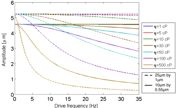
The following figure represents a survey of cantilevered rod amplitudes in various vis-cosities as a function of frequency. In the experiments detailed in Chapters 6 and 7, I utilized three different biomimetic cilia lengths and diameters: 25 µm by 2µm, 25µm by
1µm, and 10µm by 0.55 µm. Thus, I model the amplitude dependence for two of these
rod geometries, 25 µm by 1 µm and 10 µm by 0.55 µm. The force on the rod is in the
Ex-perimentally, I apply an oscillating magnetic field ranging from 10−125 mT. Because the magnetic dipoles within a rod-shaped actuator align head-to-tail along the rod’s long axis, when a magnetic field is applied, a torque is generated as the dipoles within the rod seek to minimize the discrepancy between the applied field direction and the rod’s long axis. Magnetic torque is discussed in more detail in the next section, as it is a useful parameter for understanding the limits of an actuator’s ability for force application on a fluid, regard-less of the fluid. In this model, magnetic force is a numerical value dependent on the rod’s magnetic moment, the applied field, and the location of subsequent torque application.
25μm by 1μm 10μm by 0.55μm
Figure 3.4: Core-shell rod amplitude dependence on frequency for varying fluid viscosities (1 cP, 5 cP, 10 cP, 30 cP, 50 cP, 100 cP, and 500 cP). Notice that the longer rod length may initially have a larger amplitude; however, as viscosity increases, the amplitude is damped out much more quickly than for the shorter, smaller diameter rods. In addition, the model indicates that core-shell oscillators are overdamped for fluids withη≥1 cP.
important tools for understanding amplitude dependence on frequency in order to gauge the dynamic responsiveness of an oscillating actuator. However, these tools do not assist in determining fabrication parameters such as the amount of magnetic material which will optimize the response of an actuator in both its elasticity and magnetic permeability. For these considerations, I turn to an energy minimization model first proposed by Evans et al. in 2007 (Evans et al., 2007a).
3.3 Figure of Merit for Actuators
To be responsive, the flexibility and magnetic permeability of an actuator must be bal-anced. Achieving this balance, especially in at small scales can be difficult. For many
mi-croactuators, increasing the amount of magnetic material (or magnetic loading) increases the amount of force one can apply, but also leads to a decrease in the flexibility of the actuating structure. Therefore, it is important to design an actuator such that the highest response possible is obtained. Current designs for actuating structures include chemically or magnetically linked paramagnetic beads (Furst et al., 1998; Singh et al., 2005; Vilfan et al., 2010), thin magnetic films deposited onto flexible substrates (Judy et al., 1995; Liu, 1998; Khoo and Liu, 2001; Kudo et al., 2006), elastic polymers loaded with varying con-centrations of magnetic particles (Evans et al., 2007a; Pirmoradi et al., 2010; Fahrni et al., 2009b; Fuhrer et al., 2009; Olsson et al., 2010; Evans et al., 2012), and polymer core-metal shell structures with varying metal shell lengths (Fiser et al., 2012).
and core-shell rod-shaped actuators. The maximum bend angle, or static response, of a rod-shaped actuator is predicted based on the actuator’s magnetic loading, saturation mag-netization, and elastic modulus (Evans et al., 2007a; Evans, 2008; Evans and Superfine, 2011).
3.3.1 Energy minimization model
Ben Evans’ energy minimization model was originally designed for a homogeneous material, an example of which is the composite ferrofluid-PDMS (FFPDMS) I will describe in Section 4.2. This FFPDMS material is a suspension of magnetic nanoparticles within a flexible polymer matrix. With a few small substitutions, I am able to apply this model to a core-shell structure.
In this energy model, the first of its kind to include the effect of the magnetic field
gradient, the total energy of the rod system is defined as the sum of the elastic energyUE
of the bent rod and the magnetic energyUB of the rod in the applied magnetic field. The
magnetic energy UB is a combination of the energy due to the applied field UA(B�A), the
energy due to the rod’s internal magnetic fieldUI(�BI), and the energy due to the field felt
from neighboring rodsUN(B�N) whereBrepresents the magnetic field for each energy. The
Figure 3.5: Reprinted from Ben Evans et al., 2007. Physical parameters in the energy minimization model. The vectorm� is the rod’s magnetic moment,�Bis the applied magnetic
field, and∇B�is the magnetic field gradient. All angles shown are with respect to the vertical
axis. The angleφis the bend angle of the rod,αis the angle of the rod’s momentm, ψis
angle of the applied field, andψ� is the angle of the magnetic field gradient (Evans et al.,
2007a).
The elastic energy for a uniform rod of circular cross section is defined as (Evans et al., 2007a)
UE = π
2
Er4
L φ2 (3.21)
where E is the elastic modulus, r is the radius of the rod, and φ is the rod’s bend angle
as indicated in Figure 3.5. The magnetic energy of the rod is defined as the sum of the energies due to the applied field, the rod’s internal magnetic field, and the field felt from neighboring rods. For rod arrays such as mine with a rod spacing on the order of 10µm,