Sharif University of Technology
Scientia IranicaTransactions B: Mechanical Engineering http://scientiairanica.sharif.edu
Experimental study of the wedge eects on the
performance of a hard-chine planing craft in calm water
P. Ghadimi
, S.M. Sajedi, and S. Tavakoli
Department of Marine Technology, Amirkabir University of Technology, Hafez Ave, No 424, Tehran, P.O. Box 15875-4413, Iran. Received 23 December 2016; received in revised form 9 December 2017; accepted 23 June 2018
KEYWORDS Experimental study; Planing hull; Wedge; Performance; Calm water; Combination of experimental and theoretical studies.
Abstract. In this paper, eects of a wedge on the performance of planing craft in calm water are experimentally investigated. Experiments were carried out on three dierent cases distinguished by the wedge type. The model, built of berglass, was a prismatic planing hull with deadrise angle of 24 degrees. Towing tests were conducted at dierent Froude numbers ranging from 0.21 to 2.1. The total trim angle, resistance, and rise-up at the CG as well as stern and bow, keel wetted length, chine wetted length, stagnation angle, and the length of stagnation line were measured. They were used to study the eect of installing a wedge on the performance and the eect of height on the hydrodynamic characteristics. Based on the observations made, it was concluded that when the wedge was applied to the hull, the risk of the model exhibiting instability diminished, while total trim angle largely decreased, keel wetted length was enlarged, wetted surface became thinner, CG rise-up was lowered, and the resistance was reduced. Moreover, experimental measurements and theoretical 2D+T theory were combined to bring deeper insight into physics of the ow and pressure distribution when a wedge was installed on the bottom of a planing hull. © 2019 Sharif University of Technology. All rights reserved.
1. Introduction
Planing hulls are fast, agile, and popular boats that are used in dierent segments of marine transportations. They are characterized by the hydrodynamic load acting on their bottom, which chiey aects perfor-mance of the boat and helps them reach high speeds. This force results in reduction in the wetted surface, increase in the bow wavelength, decrease in the wave making resistance, and trimming the boat bow-up. These vessels have empowered the naval engineers to better design high-speed boats. However, the common instabilities observed in these boats, especially at high speeds [1,2], have intensied the engineers' concerns
*. Corresponding author. Tel.: +98 21 64543117; Fax: +98 21 66412495
E-mail address: [email protected] (P. Ghadimi) doi: 10.24200/sci.2018.20607
about their appropriate performance and avoiding these instabilities is a central focus for the designers. Several methods have been proposed to improve the stability of these boats in calm water and waves. For example, transom aps were used for increasing the longitudinal stability of planing hulls by De la Cruz et al. [3] and Xi and Sun [4], or proactive control of thrust force was used by van Deyzen [5].
Dynamic instabilities of planing hulls are ob-served in transverse, horizontal, and vertical planes [1]. Among these instabilities, porpoising is a well-known instability during which the boat experiences an oscilla-tory motion in the vertical plane. Through addition of some appendages like aps and wedges, this instability may be reduced or diminished [4]. The appendages can produce an extra lift in addition to the pressure lift and allow the vessel to reach a dynamic equilibrium at speeds where the vessel without any appendages would not experience it. At other speeds, this equipment may positively help the vessel to move at smaller
trim angles, which results in a smaller resistance. Appropriate understanding of the role and eects of these appendages on the performance is pivotal for the designers. In the current work, two wedges are placed at the bottom of a planing boat and their eects on the vessel performance in calm water are investigated.
One of the rst methods developed for investigat-ing the planinvestigat-ing hulls equipped with aps in the steady-state condition was proposed in the work by Savitsky and Brown [6]. They presented empirical relations for computing the lift, moment, and drag force resulting from the trim tabs. Aside from this study, the majority of the studies in this realm have focused on experimen-tal and numerical work. Millward [7] insexperimen-talled dierent wedges at the bottom of planing hulls and showed that in some specic conditions, the wedge might positively help to reduce the resistance, increase the trim, and avoid the porpoising phenomenon. Karaath and Fisher [8] used both numerical and experimental methods and showed that equipping a high-speed ship with a wedge could bring about reduction in the trim angle and resistance. In addition, Wang [9] showed that adding wedges, interceptors, and trim tabs could lead to an extra hydrodynamic force that would result in the reduction in both trim and resistance. In a study con-ducted by Tsai and Hwang [10], combination of wedge and aps was studied and discussions about the appro-priate condition for installing these appendages were presented. Moreover, Cumming et al. [11] showed that a wedge might also lead to reduction in cavitation of the propeller in the vessel. Jang et al. [12] numerically investigated the eect of a wedge on the performance of a passenger ship. The experimental work of Steen et al. [13] also presented additional insights into the eects of appendages on the performance of planing hull and reduction in possible instabilities. In recent years, Karimi et al. [14] conducted a parametric study to investigate the eects of the interceptors on the performance of planing hulls and presented statistical analysis for specifying the depth of this appendage.
Performance of the planing hulls with appendages cannot be mathematically modeled easily in both steady and unsteady conditions. For such cases, the previous semi-empirical work [15-17] and analytical work [18-20] cannot be used directly and the available empirical relations [6,21] might be applicable, which are limited to some specied conditions. Therefore, by following the previous work, the best alternatives for studying such phenomena are recommended to be numerical and experimental approaches. Accordingly, during the last decade, wide ranges of experimental studies have been devoted to studying dierent char-acteristics of the planing hulls. Performance of these hulls [22-27], their seakeeping [28,29], roll motion [30], and even steady yawed [31,32] condition have been studied. The satisfactory, promising, and useful
nd-ings of these studies signal that experimental work can be considered as a very reliable alternative methodol-ogy for investigating the planing hull characteristics.
In the current paper, a planing hull is experi-mentally modeled in a towing tank with and without a wedge. This hull is not desirably stable without a wedge. Unlike previous studies of De la Cruz et al. [3] and Streen et al. [13], who used controllable aps and interceptors to reduce instability of the boat, a xed wedge is used in the current paper in order to reduce the boat instability. Moreover, the model studied in this paper is comparatively larger than those in previous studies. Therefore, unlike the previous studies, the current paper focuses on larger Reynolds numbers. It is shown how a wedge and its height can aect the performance of the model in calm water. The problem is rstly dened and the most important parameters are introduced. The applied test methodology, the model, the facilities, and running conditions are also presented. The main results of the paper include the trim angle, the CG rise-up, the stagnation line angle, the keel wetted length, and the resistance, and it is demonstrated how a wedge can aect the performance of planing hulls. Subsequently, the empirical relation by Savitsky and Brown [6] is used and it is assessed how accurate this approach estimates the trim angle of the planing hulls by the added wedges. Later, 2D+T theory and the measured trim angle and keel wetted length are used to ascertain how a wedge can aect the longitudinal force distribution in a planing hull. Furthermore, the wedge lift is determined using the measured trim angle and keel wetted length that are implemented in 2D+T theory. Ultimately, the conclusions of the current study are presented and future work is outlined.
2. Materials and methods 2.1. Problem denition
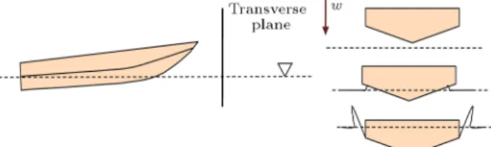
In the current experimental tests, it is aimed to nd the running attitude of planing hulls at dierent speeds and how they are inuenced by a wedge. The speed of the model is assumed to be U. Since the model speed may exceed the displacement ow regime, a hydrodynamic force is expected to be produced at the bottom of the hull. This force can push the solid body up, which can lead to a trim angle of (Figure 1). Two wetted lengths including keel wetted length (LK) and chine
wetted length (LC) are dened. The rst length refers
to the length between the transom and intersection of the calm water with keel. The latter represents the length between the transom and the longitudinal position where water drenches the chine for the rst time (by considering the water rise-up). Rise-up of the vessel is considered at three dierent positions. The rst position is the transverse section of the boat
Figure 1. A pictograph of the considered problem.
(transom), the second is the longitudinal position of CG, and the third position is the transverse section 10 (bow section). All parameters are found in an equilibrium condition. Also, the boat mat experiences a porpoising instability in vertical direction [33]. For such a condition, no trim, rise-up, keel wetted length, and resistance would be reported. The boat speed is turned into non-dimensional form using beam Froude number as in:
FrB= pUgB; (1)
where B is its beam and g is the gravity acceleration. 2.2. Physical description of the model
In the current study, a V-shape hard-chine planing hull is investigated. A 1:5 scale model made up of berglass is built. The length of the model is 2.6 m and it has length over beam (L=B) ratio of 4.78. The deadrise angle of the boat is 24 degrees at stern and constant from the stern (section A) amidships (section B); then, it increases from 24 to 40 degrees at its bow (section C). The mass of the model is 86.024 kg and its longitudinal center of gravity is located at 0.7914 m from the transom. The model has no step in its longitudinal and transverse directions. Principal characteristics of the model are displayed in Table 1 and its body prole is depicted in Figure 2.
Table 1. Principal characteristics of the investigated model.
Parameter Value
L 2638 mm
LCG 791 mm of transom
VCG 185 mm
LBP 2368 mm
C 0.5096
M 86.02 kg
V 0.08585 mm3
DB 186 mm
DT 89 mm
s 2.34 deg
DD 146 mm
B 551 mm
Cv 0-4.29
Fr 0-4.27
Figure 2. Body prole of the investigated hull.
2.3. Experimental setup
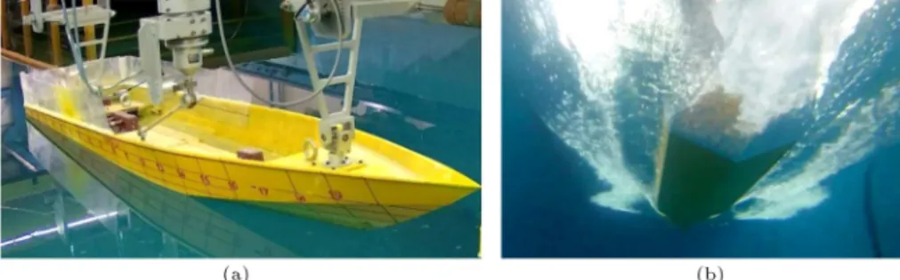
The experimental setup is based on towing method and recommendation of ITTC [34] on High Speed Marine Vehicle resistance tests. The experiments are carried out in the National Persian Gulf Towing Tank, located in Tehran. The length of the tank is 400 m, its width is 6 m, and the water depth is set to 4 m. The maximum carriage speed is 18 m/s. The characteristics of the towing tank are displayed in Table 2. The costume-built manned carrier moves on the rails and can measure dierent hydrodynamic parameters. The model is towed from its CG. During the conducted tests, the model does not exhibit any roll, sway, and yaw motions. It is xed in these directions and its initial roll and yaw angles are assumed to be zero. The drag force and the trim angle are measured during each test. The position at which drag force is measured is the intersection of the shaft and LCG. It should be noted that the angle between the shaft line and base line is 6 degrees in all the considered tests. It should be pointed out that, although the current paper explores steady performance of a model, shaft line is also considered in building of the model. This is due to the fact that it is a model of a real planing hull, which is being studied by the current authors in order to reduce the possibility of porpoising phenomenon.
The rise-up of the three reported sections is found using the installed potentiometer at the sections (as evident in Figure 3(a)). The trim angle of the boat is determined by computing the tangent of the line connecting the rise-up of the transom section (Z1) to
the rise-up of the bow (Z0) section as:
= tan 1Z10 Z1
L10 1
; (2)
where L0 10 is the longitudinal length between these
two sections. It should be noted that the boat is located at a static trim angle in each of the conducted tests and that static trim angle has signicant eects on the nal dynamic trim angle [35,36]. Therefore, if any researcher is interested in modeling according to the current paper, this point should be taken into consideration as well. Moreover, the reported values of dynamic trim angle are for the total trim angle, not for the absolute angle. It is important to state that the keel wetted length and the chine wetted length are also measured in this study. To this end, a camera, which was located under the boat and moved with the boat, was used. This camera was a 720 1280 with 30
Table 2. Characteristics of national Persian Gulf towing tank.
Parameter Value
Length of canal 400 m
Width of canal 6 m
Depth of canal 4 m
Maximum velocity of carrier 18 m/s Density of towing tank water 1002 kg/m3
Kinematic viscosity of towing tank water 9.75831E-07 m2/s
Temperature of water 21
Length of crowbar 500 mm
Distance of potentiometer 1901 mm
Height of towing situation 120.88 mm Distance between towing situation and transom 791.49 mm
Figure 3. (a) Experimental setup of the model. (b) A view of the bottom of the vessel, which is used for determining the wetted lengths.
frames in each second. At each frame, the photos were taken. The values of the wetted lengths were recorded by using the marked numbering on the body of the model. A photograph of the bottom of the model is shown in Figure 3(b). It should be pointed out that when the boat reaches steady condition, the values of wetted lengths have no variation and become xed.
Regarding the repeatability and uncertainty of the problem, it should be noted that the selected tests for the planing hull without a wedge were conducted four times and it was observed that trim angle, resis-tance, and sinkage diered by about 0.01 to 1%.
2.4. Running conditions
The targeted tests were carried out in three dierent conditions. In the rst condition, the model was not equipped with any appendages. Based on the exper-iments, this model underwent porpoising at speeds larger than 7 m/s. In the other conditions, it was attempted to add wedge to the bottom of the boat in order to lower the weight of the boat and change the position of the CG. The wedge height was selected by considering the boundary layer thickness of the boat
bottom. This layer is determined using:
(x) = 0:37Re 1=5; (3)
where Re is the Reynolds number and is found by:
Rel= vlm Lm=lk+ l2 c; (4)
where is the kinematic viscosity of the uid. In the current study, Reynolds number varies from 3:73 109
to 2:27 1010, which yields to boundary layer of 0.36
to 0.3 L by using the above equations. Therefore, the selected value for the h=L (height to length ratio) of the wedge should be smaller than 0.3. The ranges of h=L in the previous research and current study are also shown in Figure 4. Based on this gure, another point is observed that distinguishes the current study from the previous ones, which is the Reynolds number range in the tests. Unlike the previous studies in which Reynolds Number is mostly smaller than 10 109, in
the current paper, larger range of Reynolds number is considered.
Based on the reported values in Figure 3, two dierent depths of 10 and 5 mm (h=L = 0:108 and
Figure 4. Values of h=L ratio in dierent studies (reproduction of Figure 2 of Karimi et al. [14] by adding data of the current paper).
Figure 5. The installed wedge at the stern of the model.
0.054) are considered for the intended experiments. The length of the wedge is also assumed to be 92 mm. A schematic of the wedges is provided in Figure 5. It should be noted that the wedge of the height of 10 mm is named wedge-1 and the other is named wedge-2 in the current study.
For each case, 10 dierent speeds ranging from 1 to 10 are considered. Speeds of 1 and 2 m/s are recognized as the displacement regimes, speeds 3 and 4 m/s are categorized as semi-planing condition, and speeds larger than 4 are classied as planing
mode. During each run, the following parameters are determined:
1. Trim angle (in degrees);
2. Rise-up at stern, CG, and bow (in mm);
3. Keel wetted length and chine wetted length (in mm);
4. Resistance (in kgf).
3. Results and discussion
3.1. Measured parameters for each case
The data produced by the conducted tests are reported in this sub-section. In addition to the earlier men-tioned parameters, the stagnation line angle and the stagnation line length (LST) are determined for
each test. The measured parameters for the model of no wedge are displayed in Table 3. The tests are conducted at dierent speeds ranging from 1 to 10 m/s. As observed in this table, at speeds larger than 8 m/s, the model experiences vertical instability and no xed trim angle is recorded. The instability is denoted by PORP as an abbreviation of porpoising. Also, some photographs of the model at beam Froude numbers of 0.86, 1.72, 3.01, and 3.87 are illustrated in Figure 6. Moreover, it is checked whether the previous empirical equations predict the porpoising in the current model. Celano [37] suggested that porpoising of a planing hull could be determined by:
tCritical= 0:1197deg0:7561e15:7132 q
CL
2 deg0:2629; (5)
where: r
CL
2 = r
C
Cv: (6)
Table 3. Measured parameters for the case of no wedge. U
(m/s) Fr s
(deg) Z1
(mm)
ZCG
(mm)
Z10
(mm) (deg)
LC
(mm) LK
(mm)
LST
(mm) (deg)
RT
(kgF)
1 0.43 2.34 -3.1 -1.78 1.27 2.47 1608 2242 691 23.52 0.8
2 0.86 2.34 -22.7 -8.67 23.59 3.73 1496 2235 789 20.48 5.4
3 1.29 2.34 -34.59 4.03 92.8 6.17 1161 1936 823 19.59 11.55
4 1.72 2.34 -17.9 26.71 129.25 6.77 956 1780 869 18.52 13.05
5 2.15 2.34 1.64 52.61 169.75 7.39 724 1572 892 18.03 13.94
6 2.58 2.34 27.00 70.26 169.70 6.63 572 1520 987 16.23 13.65
7 3.01 2.34 46.60 81.54 161.86 5.81 445 1511 1101 14.52 13.8
8 3.44 2.34 PORP. PORP. PORP. PORP. PORP. PORP. PORP. PORP. PORP. 9 3.87 2.34 PORP. PORP. PORP. PORP. PORP. PORP. PORP. PORP. PORP. 10 4.30 2.34 PORP. PORP. PORP. PORP. PORP. PORP. PORP. PORP. PORP.
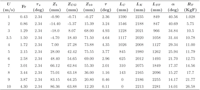
Figure 6. Photographs of the tests in the case of no wedge for dierent Froude numbers. Table 4. Measured parameters for the case with wedge 1.
U
(m/s) Fr s
(deg) Z1
(mm)
ZCG
(mm) Z10
(mm) (deg)
LC
(mm) LK
(mm) LST
(mm) (deg)
RT
(KgF) 1 0.43 2.34 -0.90 -0.71 -0.27 2.36 1590 2235 849 40.56 1.028 2 0.86 2.34 -14.40 -5.37 15.39 3.24 1546 2188 847 40.69 5.75
3 1.29 2.34 -18.0 8.07 68.00 4.93 1228 2021 966 34.84 10.5
3.5 1.50 2.34 -4.70 18.40 71.50 4.64 1117 2020 1058 31.44 10.78 4 1.72 2.34 7.00 27.28 73.88 4.35 1026 2008 1127 29.34 11.00 5 2.15 2.34 28.00 42.42 75.55 3.77 845 1980 1262 25.94 11.79 6 2.58 2.34 48.40 54.65 69.00 2.96 625 2012 1493 21.70 12.75 7 3.01 2.34 66.12 62.84 55.30 2.01 310 2075 1849 17.37 14.56 8 3.44 2.34 75.01 63.18 36.00 1.16 143 2165 2096 15.27 17.7
9 3.87 2.34 83.15 64.25 20.80 0.46 0 2186 2255 14.17 21.77
10 4.30 2.34 86.36 63.88 12.20 0.11 0 2213 2281 14.01 26.58
The above empirical equation shows that the critical total trim angle of the boat at a speed of 7 m/s is 4.8 degrees, which is smaller than the measured total trim angle. Accordingly, the equation correctly demonstrates that the model undergoes instability.
The recorded results for the case with wedge 1 are shown in Table 4. The results indicate that by installing wedge 1, the model experiences a steady movement and no instability occurs. It can also be seen that at the beam Froude numbers larger than 1.71, the chine is dry and only the keel is wetted. Maximum value of total trim angle in this condition is 4.93 degrees, which is smaller than that in the case of no wedge. Once again, some photographs of the model while being towed are depicted in Figure 7 at beam Froude numbers of 0.86, 1.72, 3.01, and 3.87.
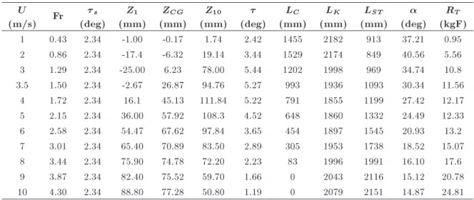
Finally, the results of the case with wedge 2 are
illustrated in Table 5. A close scrutiny of the reported parameters in this table reveals that the installed wedge also prevents possible instability and improves the vertical stability of the model. The maximum total trim angle as a result of applying this wedge is 5.27 degrees, and the wetted length of chine is again zero at the two largest speeds. Four photographs taken during the tests are shown in Figure 8 that correspond to beam Froude numbers of 0.86, 1.72, 3.01, and 3.87.
As observed in the presented tables, wedges 1 and 2 eliminate the porpoising instabilities. In order to provide a better insight into the eects of these wedges, time history of the total trim angle of the model with and without a wedge at 10 m/s speed is shown in Figure 9. As evident in this gure, when the boat advances forward without any wedge, it experiences oscillations in the direction of total trim
Figure 7. Photographs of the tests in the case with wedge 1 for dierent Froude numbers.
Figure 8. Photographs of the tests in the case with wedge 2 for dierent Froude numbers. Table 5. Measured parameters for the case with wedge 2.
U
(m/s) Fr s
(deg) Z1
(mm)
ZCG
(mm) Z10
(mm) (deg)
LC
(mm) LK
(mm) LST
(mm) (deg)
RT
(kgF)
1 0.43 2.34 -1.00 -0.17 1.74 2.42 1455 2182 913 37.21 0.95
2 0.86 2.34 -17.4 -6.32 19.14 3.44 1529 2174 849 40.56 5.56 3 1.29 2.34 -25.00 6.23 78.00 5.44 1202 1998 969 34.74 10.8 3.5 1.50 2.34 -2.67 26.87 94.76 5.27 993 1936 1093 30.34 11.56 4 1.72 2.34 16.1 45.13 111.84 5.22 791 1855 1199 27.42 12.17 5 2.15 2.34 36.00 57.92 108.3 4.52 648 1860 1332 24.49 12.33 6 2.58 2.34 54.47 67.62 97.84 3.65 454 1897 1545 20.93 13.2 7 3.01 2.34 65.40 70.89 83.50 2.89 305 1953 1738 18.52 15.07
8 3.44 2.34 75.90 74.78 72.20 2.23 83 1996 1991 16.10 17.6
9 3.87 2.34 82.40 75.52 59.70 1.66 0 2043 2116 15.12 20.78
Figure 9. Time history of the trim angle of the model at speed of 10 m/s with and without wedge.
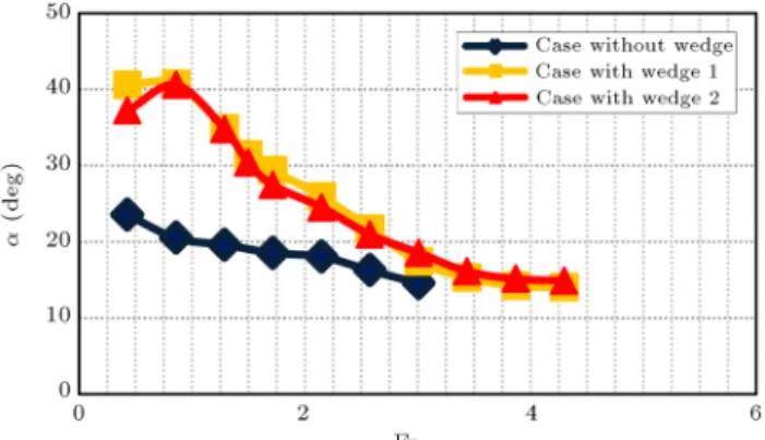
Figure 10. Comparison of the measured trim angles for dierent test cases.
angle. However, in the presence of wedges 1 and 2, the total trim angle shows a steady behavior and does not vary in time.
3.2. Comparison of dierent parameters for dierent models
Through comparison of the obtained results for dier-ent conducted test cases, one may better understand the eects of installing a wedge on a planing model and the inuence of height of this appendage at the same time. Figure 10 illustrates the measured trim angles for each test model at dierent beam Froude numbers. As evident in this gure, by installing a wedge at the bottom of the model, trim angle of the model decreases on top of preventing the vertical instability. The results also show that the case with wedge 1 has smaller trim angles than the case with wedge 2. This shows that for a wedge with larger depth, the trim angle is reduced more signicantly. It should be noted that when the wedge depth increases, it lowers the ecient weight of the model further. As a result, the trim angle should be further reduced. It should be noted that in the previous research by Millward [7], such phenomenon was also observed. His results showed that boat trim angle decreased by 25-33% when a wedge was added to the bottom of the boat. At larger speeds, the reduction was more signicant, and this behavior is like what is observed in the current study. However, here, these reductions are about 13-49% when wedge 1
Figure 11. Comparison of the measured CG rise-ups for dierent test cases.
Figure 12. Comparison of the measured stagnation line angles for dierent test cases.
is used. Meanwhile, wedge 2 reduces the trim angle of the vessel by 7 to 37%. As stated earlier, the current research explores the eects of the wedge height on the performance of a planing hull, while the work by Millward [7] focused on the inclination angle of the wedge. Moreover, the length of the model in the current study is large; hence, the Reynolds number is dierent.
The measured rise-ups of CG for all three cases are illustrated in Figure 11. Based on the presented results, when the wedge is added to the hull, the rise-up of CG decreases at beam Froude numbers larger than 2.15 and the model tends to be pushed down at beam Froude numbers larger than 0.86. Also, the case with wedge 1 has lower rise-up than the case with wedge 2. It can thus be concluded that larger depth of the wedge leads to a decrease in the CG rise-up. It is again noteworthy that in the previous work by Millward [7], it was observed that adding a wedge to the bottom of a planing boat had no signicant eects on the CG rise-up, and such phenomenon is also observed in the current paper. The reduction in CG is much smaller than the reductions observed in trim angle.
The measured stagnation angles of dierent test cases are presented in Figure 12. Based on the reported results, when the wedge is installed on the
model, the stagnation line angle signicantly increases. This implies that installing a wedge may yield a thin wetted surface. However, this may negatively aect the transverse stability of the model [38]. A comparison between both of the test cases involving a wedge shows that at Froude numbers of 2.15 to 3.01, the case with larger depth has larger stagnation line, but at larger speeds, this dierence decreases.
Figure 13 displays the measured keel wetted
Figure 13. Comparison of the measured keel wetted lengths for dierent test cases.
lengths for all of the three test conditions. Through comparison of LK versus Froude number (Fr) plots, it
can be concluded that when a wedge is added to the model, the keel wetted length of the model increases. The observed increase associated with wedge 1 is larger than that with wedge 2, which shows that larger depth of the wedge leads to a larger keel wetted length. Overall, the keel wetted length is decreased by 2 to 33% when wedge 1 is used, and by 2 to 28% when wedge 2 is used.
In order to provide a better understanding of the wetted surface and wedge eects on it, the top view of the measured wetted surfaces is displayed in Figure 14. Based on the presented results in this gure, it can be concluded that at the rst three speeds, which are not categorized as planing regime, the wedge does not have signicant eect on the wetted surface; also, for all three test cases, a similar top view of the wetted surface is observed. However, as the speed increases and beam Froude number approaches 1.72, the wedge eect on the wetted surface becomes considerable. Meanwhile, the keel wetted length becomes larger, the chine wetted
Figure 14. Top view of the measured wetted surfaces of the models at dierent speeds: (a) Fr = 0:43, (b) Fr = 0:86, (c) Fr = 0:1:29, (d) Fr = 1:72, (e) Fr = 2:5, (f) Fr = 2:58, (g) Fr = 3:01, (h) Fr = 3:44, (i) Fr = 3:87, and (j) Fr = 4:3.
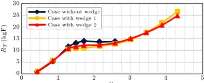
Figure 15. Comparison of the measured resistances for dierent test cases.
length becomes smaller, and the wetted surface gets thinner. The obtained results in the case with wedges 1 and 2 prove that for the larger wedge depth, the wetted surface becomes thinner.
The computed resistances of the considered cases are displayed in Figure 15. The results reveal that the resistances of all three cases are almost similar at Froude numbers smaller than 1.29. Beyond this Froude number, the case of no wedge produces larger resistance than the cases with wedge do. Based on the results in Figure 16, resistance in the case with wedge 1 is smaller at Froude numbers lower than 3.44. However, beyond this specic Froude number, the resistance of the case with wedge 2 becomes smaller. This is indicative of the fact that for the case with larger wedge depth, the resistance nally becomes smaller. Overall, it may be concluded that the larger wedge depth may lower the trim angle, but it can lead to a large resistance. Therefore, for selection of an appropriate wedge, an optimization procedure must be applied. In the current paper, resistance of the planing hull is reduced by 6-15%, when wedge 1 is used, and it is reduced by 2-11% when wedge 2 is used. In comparison with previous studies, it should be mentioned that Karimi et al. [14] reported a reduction by 3.3 to 11% when interceptors with height to length ratio of 0.4 were used. Also, the results of Karimi et al. [14] showed that resistance was reduced by 8-19% when an interceptor with height to length ratio of 0.6 was used. The results of the current study show that the installed wedges yield promising results, especially in the case of wedge 1. It should be stated that the height to length ratios of wedges 1 and 2 are respectively 0.1 and 0.05.
As proposed by ITTC, the resistance of a planing hull can be written in the form of:
RT = RP A+ RW S RF + RR+ RW S;
RT=12U2SP ACF+12U2SP ACR+12U2SW SCF;
(7) where subscripts PA and WS refer to pressure area and whisker spray area, respectively. On the other hand, F and R denote the friction and residual forces.
Figure 16. Comparison of the measured CT values for
dierent test cases.
Figure 17. Comparison of the measured CR values for
dierent test cases.
S represents the wetted surface and C represent the force coecient. It should be pointed out that there might be frictional resistance over whisker spray area as well [39,40]. The coecients related to the resistance components may be determined using:
CT = CF+ CR+ CF W SSSW S
P A; (8)
as proposed by Begovic and Bertorello [27]. It would be interesting to nd CR and CT of each case and
eects of the wedge and its height on these coecients. Total resistance coecients of all test models are illustrated in Figure 16. Based on the plots shown in this gure, a wedge may lead to larger total resistance coecient only at the rst two Froude numbers, but it lowers the peak value. Beyond this Froude number, the case equipped with wedge 1 produces the smallest resistance coecient among all test conditions. However, the case with wedge 2 has larger value of CT than the case with wedge 1. Meanwhile, it
should be noted that as Froude number increases, the dierence between CT values of the cases with wedge
1 and wedge 2 diminishes and their values become approximately similar at Froude number of 1.92. Measured values of CR are displayed in Figure 17.
Again, what occurred for CT is observed for CR.
4. Mathematical analyses
4.1. Examining Savitsky's method in determining the trim angle
Savitsky and Brown [6] relation in predicting the trim angle is provided. This is done to nd how this method and presented equations by Savitsky and Brown [6] can predict the trim angle of a planing hull equipped with a wedge, in comparison with the obtained experimental data in the current study. Also, it can be determined how the assumption of static trim angle can aect the results of this method. It is important to comment that fast prediction of the performance of a planning hull in early-stage design is always important for the engineers. Therefore, the authors would like to take advantage of the current experimental data to examine Savitsky's method in estimating the performance of planning hulls with a wedge and possible sources of error. Savitsky and Brown [6] proposed that the lift of a ap might be computed by:
F = 0:14025LFB2U2
; (9)
where LF is the ap chord, which is hereby set to the
wedge length. is the ap span-beam ratio, which, in the current study, is set to the beam to span-beam ratio of the wedge, while is the ap angle with the direction of base line that is set to the wedge angle in the current research. Based on the suggestion made by Savitsky and Brown [6], the appendage may lead to reduction in the hull mass as in:
me= m gF; (10)
and shifting of the longitudinal center of gravity as in: LCGe=(mg LCG 0:6 m F B)
eg : (11)
Savitsky and Brown [6] proposed that the values found by empirical Eqs. (8) to (10) be implemented in Savitsky's [15] relation in order to nd the equilibrium condition. Based on Savitsky's method [15], the lift force coecient (CL) is determined by:
CL0= 1:1
0:0120:5+0:00552:5
C2 V
; (12)
CL= CL0 0:0065CL00:6; (13)
where is the normalized mean wetted length and can be found by:
= LK2B+ LC; (14) and CL0 is the lift force coecient of planing plate.
The center of pressure is found by:
cp= 0:75 5:21C21 V
2 + 2:39
: (15)
Using Savitsky's method [15], the trim angles for all of the considered conditions are computed and compared with the current experimental results. In the current paper, a computer program previously developed and validated by Ghadimi et al. [21] is utilized for this purpose. Comparison of the experimental data with those of Savitsky and Brown [6] relations is displayed in Figure 18. Based on the presented plots in the case of no wedge, the empirical relations estimate the trim angle with relatively good ability. This shows that when Reynolds number is high, like in the current case, the h=L ratio of the wedge is near 5% and there is no source of error in Savitsky's method. For the case with wedge 1, Savitsky's method [16] with input from the current experiments leads to larger error. In this case, Reynolds number is high, static trim angle is also relatively large (2.43 degrees), and moreover, the h=L ratio of the wedge is about 0.1%. Therefore, it can be concluded that when Savitsky's method [15] and the empirical relation by Savitsky and Brown [6] are used for estimation of the trim angles of the hulls with a wedge, and Reynolds number is higher than 109, the
static trim angle is large and wedge depth is high, and sources of error are augmented and yield larger values of trim angle.
4.2. Longitudinal force distribution
It would also be interesting to nd how a wedge can aect the hydrodynamic force distribution in longitu-dinal direction of a planing hull, because when a wedge is installed on the bottom of a vessel, a large amount of pressure is produced by the wedge. Therefore, distribu-tion of the vertical force highly changes when a wedge
Figure 18. Comparison of the predicted trim angles by Savitsky's method [15] and experimental data: (a) No wedge, (b) wedge 1, and (c) wedge 2.
Figure 19. 2D+T theory for the steady-state problem of the current planing model.
is added. In the current subsection, this phenomenon is explored. For this purpose, 2D+T theory is used. This theory has been accepted as an appropriate theoretical model for hydrodynamic simulation of planing hulls in calm water [41-43] and in waves [44-47] as well as roll motion [48-51]. It is considered that the model passes through a transverse plane and the three-dimensional problem can be reduced to a water entry of a solid body with wedge section, as shown in Figure 19.
The water entry problem can be solved from time zero to an ending time determined by:
te=U cos LK ; (16)
and the solid body enters the uid with a speed:
w = U sin : (17)
Dynamic pressure distribution over the wall of the wedge can be computed using analytical scheme, nu-merical methods [52-67], or experimental measure-ments [68-74]. Here, the Wagner solution [75] is used as in:
p = "
wc _c p
c2 y2
w2
2 y2
c2 y2
#
; (18)
where c is the half beam of spray root at each section, _c is the time derivative of c, and y is the lateral distance from the wedge apex. Parameter c and its time derivative may be found using:
c = 2tan wt ;
_c = 2tan w ; (19) when the water has not drenched the chine. As this happens, the boundary condition P = 0 is applied to the chine. The 2D hydrodynamic force can then be determined by integrating of the pressure over the wedge body as in:
f2D HD =
Z
S
pnzdy: (20)
Also, force is reduced at each section in order to
correlate the 2D force with the 3D force. Accordingly, the reduction function introduced by Garme [76] is applied, which is:
Ctr= tanh
2:5 0:34BCVx
; (21)
where x is the longitudinal distance from the transom. Therefore, force at each section is calculated by:
f2D
HD = CtrfHD2D: (22)
2D hydrodynamic forces for each test case are com-puted by implementing the measured trim angle and keel wetted length as inputs. These values are im-plemented in the above-mentioned equations and the 2D forces are determined. The estimated 2D force distribution is computed using a previously developed and validated computer program by Ghadimi et al. [40], which is shown in Figure 20. Based on the obtained results, installing a wedge on the bottom of the test model at each speed causes a signicant reduction in the sectional forces. It is obvious that maximum value of the force produced at the position where chine gets wet is larger for the cases of no wedge. Also, at all other locations, this case displays larger values. A comparison between sectional forces of the cases with wedge 1 and wedge 2 indicates that for the case equipped with wedge 2, the forces are larger. This shows that wedge 2 has smaller contribution than wedge 1 to supporting the boat weight. At Froude numbers of 1.79, 1.92, and 2.1, no sectional force is reported for the case of no wedge, since the model undergoes porpoising phenomenon at these speeds. It should be noted that at Froude numbers of 1.92 and 2.1, the values of sectional forces for wedge 2 are very small. This may be attributed to the nature of 2D+T theory. This method may not have accurate results for trim angles smaller than 1 degree [77,78], while for the case with wedge 1, the trim angle is smaller than 1 at these speeds.
4.3. Wedge lift computation
Finally, the produced lift by the wedge is estimated in this subsection using the measured trim angle and keel wetted length. Here, the 2D+T theory is used and the measured values are implemented to nd the sectional forces. Subsequently, these forces are extended in the longitudinal direction. Integrating the sectional hydrodynamic force leads to:
F3D HD=
0 @Z
LK
Ctrf2Ddx
1
A cos : (23) The sectional hydrostatic force is computed using the submerged area of each section as in:
F3D HS=
Z
LK
Figure 20. Distributions of 2D normal force in longitudinal direction at (a) Fr = 0:43, (b) Fr = 0:86, (c) Fr = 0:1:29, (d) Fr = 1:72, (e) Fr = 2:5, (f) Fr = 2:58, (g) Fr = 3:01, (h) Fr = 3:44, (i) Fr = 3:87, and (j) Fr = 4:3.
The total lift due to hydrostatic and hydrodynamic sectional forces is computed by summation of these components as in:
L = F3D
HD+ FHS3D: (25)
The lift force produced by the wedge is computed by:
F = mg L: (26)
The sectional forces and the 3D values are again found using the developed program by Ghadimi et al. [20]. The estimated wedge lift computed by 2D+T theory and by implementing the measurements is dis-played and compared with the results of Savitsky and Brown [6] empirical relation (Eq. (8)) in Figure 21. It can be observed that for wedge 1, Eq. (8) yields larger lift than the estimated values, but for wedge 2, the predicted values by Eq. (8) and estimated values agree with each other. Also, as observed, for wedge 1 in which h=L is slightly large, the resulting error increases.
5. Conclusions
In the current study, the eects of an installed wedge on the performance of a planing hull were investigated by using towing test models. Three dierent test cases of no wedge, with wedge 1, and with wedge 2 were considered. This research was dierent from the previous research in so many ways. First, a wedge was added to the bottom of the vessel in order to reduce the possibility of porpoising in a planing hull. In addition, the length of the model was considerably larger than those of the other models. Moreover, the range of the Reynolds number in the current study was much larger than those in the previous work.
The trim angle, resistance, rise-up, and wetted length were measured during the conducted tests. The reported results indicated that the model of no wedge experienced an instable unsteady motion at high speeds. As a wedge was installed on this model, the
Figure 21. Comparison of the estimated lift of the wedge by implementing the measurements in 2D+T theory and the results of Savitsky and Brown empirical equation [6]: (a) Wedge 1, and (b) wedge 2.
porpoising diminished. The presented time history of the trim angle plots supported this assessment. The comparison of the results for dierent test cases with and without wedge showed that:
1. Installing a wedge on a planing hull led to a lower trim angle. Trim angle was reduced by 13 to 49% when wedge 1 was used, and this parameter decreased by 7 to 39% when wedge 2 was used;
2. As a wedge was added to the body, the resistance decreased. The investigations showed that this force was reduced by 6 to 15% when wedge 1 was used. Moreover, wedge 2 reduced the resistance of the vessel by 2 to 11%;
3. The keel wetted length increased when a wedge was applied. Wedge 1 increased the keel wetted length by 2 to 33% and wedge 2 did the same by 2 to 28%;
4. Total resistance and residual resistance coecients decreased when the wedge was added to the body;
5. The wetted surface of a planing hull became nar-rower when the wedge was installed. The stagna-tion angle increased by 48 to 99% when wedge 1 was used. Moreover, when wedge 2 was used, stagnation angle grew by 44 to 97%.
It was also found that for the case with larger wedge height, the trim angle decreased further. Moreover, the case with smaller wedge height had smaller resistance at high speeds and its keel wetted length was also smaller. Thicker wetted surface was observed for the case with larger wedge height. The total resistance and residual resistance coecients of the case with smaller wedge height were larger at all speeds, except for the last two, which had Froude numbers of 1.92 and 2.21.
The method by Savitsky and Brown [6] was used to predict the trim angle of the boat with a wedge. It was concluded that for the case with wedge 2, errors were very small. However, for the case with wedge 1, the error was large. The 2D+T theory was also used to nd the sectional force distribution and it was observed
that the wedge chiey lowered the sectional force peak and its value. The measured keel wetted lengths and trim angle were implemented in 2D+T theory in order to determine the lift produced by the wedge. The obtained results were compared with predicted results by the previous empirical relations. Based on the conducted comparison, the estimated value for the wedge with smaller height and the value computed by empirical relation were similar.
The current work showed the eects of an in-stalled wedge on the performance of a planing hull in calm water in detail. It can help the naval engineers to understand how to improve the stability of a planing boat in calm water. However, eects of the wedge on motions of a planing hull in waves still need to be investigated more deeply. Future studies may focus on experimental work on the eect of a wedge on the vertical motion amplitudes and the bow acceleration in regular waves.
Compliance with Ethical Standards
The authors express their sincere gratitude for the cooperation they received from \National Persian Gulf Towing Tank" during the experiments. They received no specic grant from any funding agency in the public, commercial, or not-for-prot sectors. The authors also declare that they have no conict of interest.
Nomenclature 2D+T theory
c Half beam of spray root
c0 Time derivative of half beam of spray
root
Ctr Reduction ratio
f2D
HD 2D hydrodynamic force (N/m)
f3D
HD 3D hydrodynamic force (N/m)
f2D
f3D
HS 3D hydrostatic force (N/m)
p Pressure (N/m2)
t Time (s)
te Ending time of solving solid body
water entry (m) w Water entry speed (s)
y Lateral distance from the wedge apex (m)
Characteristics of the model B Beam (m)
DB Draft at bow
DD Design draft
DT Draft at transom
L Length (m)
LBP Length Between Perpendiculars (m) LCG Longitudinal Center of Gravity m Mass (kg)
V Volume (m3)
VCG Vertical Center of Gravity (m) x Distance from transom Deadrise angle (deg) Weight (N)
S Static trim angle (deg)
Coecients
CF Frictional resistance coecient,
CF = RF=(12U2SP A)
CF W Frictional resistance coecient
of whisker spray, CF =
RF W S=(12U2SW S)
CL Lift coecient, CL= L=(12U2B2)
CL0 Lift coecient of a at planing plate,
CL= L=(12U2B2)
CR Residual resistance coecient,
CR= RR=(12U2SP A)
CT Total resistance coecient
CV Speed coecient, CV = U=pgB
C Weight coecient, C= U=(gB3)
FrL Froude number, Fr = U=pgL
Re Reynolds number, Re = UL=
Hydrodynamic characteristics of mode during steady motion
cp Longitudinal center of pressure
L Lift force (N)
LC Chine wetted length (mm)
LK Keel wetted length (mm)
LM Mean wetted length (mm)
LS Stagnation line length (mm)
LCGe Eective longitudinal center of gravity
(m)
me Eective mass (kg)
RF Friction resistance (kgF)
RF W S Whisker spray resistance (kgF)
RR Residual resistance (kgF)
SP A Pressure area (m2)
SW A Spray area (m2)
RT Total resistance (kgF)
U Speed (m/s) ZCG CG rise-up (mm)
Z1 Rise-up at stern (mm)
Z10 Rise-up at bow (mm)
Stagnation angle (deg) (x) Boundary layer thickness (m) Normalized mean wetted length
= (LK+ LC)=2B
Trim angle (deg) Flap and wedge
Lf Length of ap (m)
f Deection angle of ap (deg)
f Lift produced by ap (N)
Flap span-beam ratio Physical parameters
g Gravity acceleration (m/s2)
Density of uid (kg/m3)
Kinematic viscosity of uid (m2/s)
References
1. Blount, D.L. and Codega, L.T. \Dynamic stability of planing boats", Int. J. of Marine Technology, 29(1), pp. 4-12 (1992).
2. Katayama, T., Taniguchi, T., and Habara, K. \Tank tests to estimate onset of dynamic instabilities of high-speed planing craft", 2th Int. Conf. Chesapeake Power Boat, Annapolis, MD, USA (2010).
3. De la Cruz, J.M., Aranda, J.M., Girson sierra, F., et al. \Improving the comfort of a fast ferry", IEEE Control System Magazine, 24(2), pp. 47-60 (2004).
4. Xi, H. and Sun, J. \Vertical plane motion of high speed planing vessels with controllable transom aps: modeling and control", 16th Int. Triennial World
Congress of International Federation of Automatic Control, Prague, Czech Republic (2005).
5. van Deyzen, A. \Improving the operability of planing monohulls using proactive control", PhD Thesis, Delft TU, Delft, Netherlands (2014).
6. Savitsky, D. and Brown, P.W. \Procedures for hydro-dynamic evaluation of planning hulls in smooth and rough water", Int. J. of Marine Technology, 13(4), pp. 381-400 (1976).
7. Millward, A. \Eect of wedges on the performance characteristics of two planing hulls", Int. J. of Ship Research, 20(4), pp. 224-232 (1987).
8. Karaath, G. and Fisher, S. \The eect of stern wedges on ship powering performance", Int. J. of Naval Engineers, 99(3), pp. 27-38 (1987).
9. Wang, C.T. \Wedge eect on planing hulls", Int. J. of Hydronautics, 14(4), pp. 122-124 (1980).
10. Tsai, F. and Hwang, J.L. \Study on the compound eects of interceptor with stern ap for two fast mono-hulls", Conference: Oceans '04 MTS/IEEE Techno-Ocean '04 (2004).
11. Cumming, D., Pallard, R., Thornhill, E., Hally, D., and Dervin, M., Hydrodynamic Design of a Stern Flap Appendage for the HALIFAX Class Frigates, Mari-Tech, Halifax, N.S (June 14-16, 2006).
12. Jang, S.H., Lee, H.J., Joo, Y.R., Kim, J.J., and Chun, H.H. \Some practical design aspects of appendages for passenger vessels", Int. J. of Naval Architecture and Ocean Engineering, 1, pp. 50-56 (2009).
13. Steen, S., Alterskjar, S.A., Velgaard, A., and Aasheim, I. \Performance of a planing craft with mid-mounted interceptor", 10th Int. Conf. on Fast Sea Transporta-tion, Athens, Greece (2009).
14. Karimi, M.H., Seif, M.S., and Abbaspoor, M. \An experimental study of interceptor's eectiveness on hy-drodynamic performance of high-speed planing crafts", Polish Maritime Research, 20, pp. 21-29 (2013).
15. Savitsky, D. \Hydrodynamic design of planing hulls", Int. J. of Marine Technology, 1(1), pp. 71-95 (1964).
16. Ikeda, Y., Yokmi, K., Hamaski, J., Umeda, N. and Katayama, T. \Simulation of running attitudes and resistance of a high-speed craft using a database of hydrodynamic forces obtained by fully captive model experiments", 2th Int. Conf. on Fast Sea Transporta-tion, Athens, Greece (1993).
17. Ghadimi, P., Tavakoli, S., Feizi Chakab, M.A., and Dashtimanesh, A. \Introducing a particular mathe-matical model for predicting the resistance and per-formance of prismatic planing hulls in calm water by means of total pressure distribution", Int. J. of Naval Architecture and Marine Engineering, 12(2), pp. 73-94 (2015).
18. Martin, M. \Theoretical determination of porpoising instability of high-speed planing boat", Report No. 76-0068 David Taylor Naval Ship Research and Develop-ment Center (1976).
19. Xu, L. and Troesch, A.W. \A study on hydrodynamic of asymmetric planing surfaces", 5th Int. Conf. on Fast Sea Transportation, Seattle, Washington, USA (1999).
20. Ghadimi, P., Tavakoli, S., Dashtimanesh, A., and Za-manian, R. \Steady performance prediction of a heeled planing boat in calm water using asymmetric 2D+T model", Proceedings of the Institution of Mechanical Engineers, Part M: Journal of Engineering for the Maritime Environment, 231(1), pp. 234-257 (2016a).
21. Ghadimi, P., Loni, A., Nowruzi, H., Dashtimanesh, A., and Tavakoli, S. \Parametric study of the eects of trim tabs on running trim and resistance of planing hulls", Int. J. of Advances in Shipping and Ocean Engineering, 3(1), pp. 1-12 (2014).
22. Taunton, D.J., Hudson, D.A., and Shenoi, R.A. \Char-acteristics of a series of high speed hard chine planing hills- Part 1: Performance in calm water", Int. J. of Small Craft Technology, 152(2), pp. B55-B74 (2010).
23. Begovic, E. and Bertorello, C. \Resistance assessment of warped hull form", Int. J. of Ocean Engineering, 56, pp. 28-42 (2012).
24. Ma, W.J., Sun, H.B., Zou, J., and Zhaung, J.Y. \Test studies of the resistance and seakeeping performance of trimaran planing hull", Polish Maritime Research, 22, pp. 22-27 (2015).
25. Jiang, Y., Zou, J., Hu, A., and Yang, J. \Analysis of tunnel hydrodynamic characteristics for planing trimaran by model test and numerical simulations", Int. J. of Ocean Engineering, 113, pp. 101-110 (2016).
26. Kim, D.J., Kim, S.Y., You, Y.J., et al. \Design of high-speed planing hulls for the improvement of resistance and seakeeping performance", Int. J. of Naval Archit Ocean Eng., 5, pp. 161-177 (2013).
27. Seo, J., Chori, H.K., Jeong, U.C., et al. \Model tests on resistance and seakeeping performance of wave-piercing high-speed vessel with spray rails", Int. J. of Naval Archit Ocean Eng., 8(5), pp. 442-455 (2017).
28. Taunton, D.J., Hudson, D.A., and Shenoi, R.A. \Char-acteristics of a series of high speed hard chine planing hills- Part 2: Performance in waves", Int. J. of Small Craft Technology, 153(1), pp. B1-B22 (2011).
29. Begovic, E., Bertorello, C., and Pennino, S. \Experi-mental seakeeping assessment of a warped planing hull model series", Int. J. of Ocean Engineering, 83, pp. 1-15 (2014).
30. Judge, C.Q. and Judge, J.A. \Measurement of hydro-dynamic coecients on a planing Hull using forced roll oscillations", Int. J. of Ship Research, 57, pp. 112-124 (2013).
31. Morabito, M.G. \Prediction of planing hull side forces in yaw using slender body oblique impact theory", Int. J. of Ocean Engineering, 101, pp. 47-57 (2015).
32. Morabito, M., Pavkov, M., Timmins, C., and Beaver, B. \Experiments on directional stability of stepped planing hulls", Proceedings of the 4th Chesapeake Power Boat Symposium, Annapolis, MD, US (2014).
33. Katayama, T. \Mechanism of porpoising instabilities for high-speed planing craft", Proceedings of the Sixth ISOPE Pacic/Asia Oshore Mechanics Symposium (2004).
34. ITTC Recommended Procedures and Guidelines, 24th ITTC 7.5-02 07-02.1 (2005).
35. Lee, E.J., Schleicher, C.C., Merrill, C.F., Fullerton, D.A., et al. \Benchmark testing of generic prismatic planing hull (GPPH) for validation of CFD tools", In proceedings of the 30th American Towing Tank Conference (ATTC), Bethesda, Maryland (2017).
36. Lee, E., Fullerton, A., Geiser, L., Schleicher, C., et al. \Experimental and computational comparisons of the R=V Athena in calm water", In Proceedings of the 31st Symposium on Naval Hydrodynamics, Monterey, CA, USA (2016).
37. Celano, T. \The prediction of porpoising inception for modern planing craft", SNAME Transaction, 106, pp. 296-292 (1998).
38. Katayama, T., Fujimoto, M., and Ikeda, Y. \A study in transverse stability loss of planing craft at super high forward speed", In 9th Int. Conf. on Stability of Ships and Ocean Vehicles, Rio de Janerio, Brazil (2006).
39. Savitsky, D., DeLorme, M.F., and Datla, R. \Inclu-sion of whisker spray drag in performance prediction method for high-speed planing hulls", Int. J. of Marine Technology, 44(1), pp. 35-56 (2007).
40. Ghadimi, P., Tavakoli, S., Dashtimanesh, A., and Pirooz, A. \Developing a computer program for de-tailed study of planing hull's spray based on Morabito's approach", Int. J. of Marine Science and Application, 13(4), pp. 402-415 (2014).
41. Akers, R.H. \Dynamic analysis of planing hulls in vertical plane", In Proceedings of the Society of Naval Architects and Marine Engineers, New England Sec-tion (1999).
42. Ghadimi, P., Tavakoli, S., and Dashtimanesh, A. \Calm water performance of hard-chine vessels in semi-planing and semi-planing regimes", Polish Maritime Res., 23(4), pp. 23-45 (2016).
43. Van Deyzen, A. \A nonlinear mathematical model for motions of a planing monohull in head seas", 6th Int. Conf. on High Performance Marine Vehicles, Naples, Italy (2008).
44. Zarnick, E.E. \A nonlinear mathematical model of motions of a planing boat in regular waves", Report No. 78/032, David Taylor Naval Ship Research and Development Center (1978).
45. Garme, K. and Rosen, A. \Time domain simulations and full-scale trials on planing crafts in waves", Int. J. of Ship Building Progress, 50(3), pp. 177-208 (2003).
46. Ghadimi, P., Tavakoli, S., and Dashtimanesh, A. \Coupled heave and pitch motions of planing hulls at non-zero heel angle", Int. J. of Applied Ocean Research, 59, pp. 286-303 (2016).
47. Haase, H., Sopron, J.P., and Abdel-Maksoud, M. \Numerical analysis of a planing boat in head waves using a 2D+T method", Int. J. of Ship Technology Research, 62(3), pp. 131-139 (2015).
48. Sebastiani, L., Bruzzone, D., Gualeni, P., et al. \A practical method for the prediction of planing craft motions in regular and irregular waves", 27th Int. Conf. on Oshore Mechanics and Arctic Engineering, Estoril, Portugal (2008).
49. Tavakoli, S., Ghadimi, P., Dashtimanesh, A., and Sa-hoo, P.K. \Determination of hydrodynamic coecients related to roll motion of high-speed planing hulls", 13th Int. Conf. on Fast Sea Transportation, DC, USA (2015).
50. Ghadimi, P., Tavakoli, S., and Dashtimanesh, A. \An analytical procedure for time domain simulation of roll motion of the warped planing hulls", Proceedings of the Institution of Mechanical Engineers, Part M: Int. J. of Engineering for the Maritime Environment, 230, pp. 600-615 (2016).
51. Tavakoli, S., Ghadimi, P., and Dashtimanesh, A. \A nonlinear mathematical model for coupled heave, pitch, and roll motions of a high-speed planing hull", Int. J. of Engineering Mathematics, 104, pp. 157-194 (2017).
52. Ghadimi, P., Tavakoli, S., Dashtimanesh, A., and Taghikhani, P. \ Dynamic response of a wedge through asymmetric free fall in 2 degrees of freedom", Proceed-ings of the Institution of Mechanical Engineers Part M: Int. J. of Engineering for the Maritime Environment, Published Online, 233(1), pp. 229-250 (2017).
53. Farsi, M. and Ghadimi, P. \Finding the best combi-nation of numerical schemes for 2D SPH simulation of wedge water entry for a wide range of deadrise angles", Int. J. of Naval Archit Ocean Eng., 6, pp. 638-651 (2014).
54. Farsi, M. and Ghadimi, P. \Eect of at deck on catamaran water entry through smoothed particle hydrodynamics", Institution of Mechanical Engineer-ing, Part M: Int. J. of Engineering for the Maritime Environment, Published Online, Marc, 230(2), pp. 267-280 (2014).
55. Facci, A.L., Panciroli, R., Ubertini, S., and Porri, M. \Assessment of PIV-based analysis of water entry problems through synthetic numerical datasets", Int. J. of Fluids and Structures, 55, pp. 484-500 (2015).
56. Ghadimi, P., Feizi Chekab, M.A., and Dashtimanesh, A. \A numerical investigation of the water impact of an arbitrary bow section", ISH Journal of Hydraulic Engineering, 19(3), 186-195 (2013).
57. Shademani, R. and Ghadimi, P. \Parametric investi-gation of the eects of deadrise angle and demi-hull separation on impact forces and spray characteristics of catamaran water entry", Int. J. of the Brazilian Society of Mechanical Sciences and Engineering, 39(6), pp. 1989-1999 (2017).
58. Shademani, R. and Ghadimi, P. \Numerical assess-ment of turbulence eects on forces, spray parameters, and secondary impact in wedge water entry problem using k-epsilon method", Int. J. of Scientia Iranica, published online, 24(1), pp. 223-236 (2017).
59. Shademani, R. and Ghadimi, P. \Asymmetric water entry of twin wedges with dierent deadrises, heel angles, and wedge separations using nite element based nite volume method and VOF", Int. J. of Applied Fluid Mechanics, 10(1), pp. 353-368 (2017).
60. Feizi Chekab, M.A., Ghadimi, P., and Farsi, M. \Investigation of three-dimensionality eects of aspect ratio on water impact of 3D objects using smoothed particle hydrodynamics method", Int. J. of the Brazil-ian Society of Mechanical Sciences and Engineering, 38(7), pp. 1987-1998 (2016).
61. Shademani, R. and Ghadimi, P. \Estimation of water entry forces, spray parameters and secondary impact of xed width wedges at extreme angles using -nite element based -nite volume and volume of uid methods", Int. J. of Brodogradnja, 67(1), pp. 101-124 (2017).
62. Farsi, M. and Ghadimi, P. \Simulation of 2D symme-try and asymmesymme-try wedge water ensymme-try by smoothed particle hydrodynamics method", Int. J. of the Brazil-ian Society of Mechanical Sciences and Engineering, 37(3), pp. 821-835 (2017).
63. Ghadimi, P., Dashtimanesh, A., and Djeddi, S.R. \Study of water entry of circular cylinder by using analytical and numerical solutions", Int. J. of the Brazilian Society of Mechanical Sciences and Engineer-ing, 34(3), pp. 225-232 (2015).
64. Korobkin, A.A. \Second-order Wagner theory of wave impact", Int. J. of Engineering Mathematics, 58(1-4), pp. 121-139 (2007).
65. Ghadimi, P., Saadatkhah, A., and Dashtimanesh, A. \Analytical solution of wedge water entry by using schwartz-christoel conformal mapping", Int. J. of Modeling, Simulation and Scientic Computing, 2(3), pp. 337-354 (2013).
66. Judge, C., Troesch, A.W., and Prelin, M. \Initial water impact of a wedge at vertical and oblique angles", Int. J. of Eng. Math, 48, pp. 279-303 (2004).
67. Ghadimi, P., Feizi Chekab, M.A., and Dashtimanesh, A. \Numerical simulation of water entry of dierent arbitrary bow sections", Int. J. of Naval Arch. Marine Eng., 11, pp. 117-129 (2014).
68. Panciroli, R. and Porri, M. \Evaluation of the pres-sure eld on a rigid body entering a quiescent uid through particle image velocimetry", Exp. Fluids, 54, pp. 1630-1642 (2013).
69. Jalalisendi, M., Osma, S.J., and Porri, M. \Three-dimensional water entry of a solid body: a particle image velocimetry study", Int. J. of Fluids and Struc-tures, 59, pp. 85-102 (2015).
70. Jalalisendi, M., Shams, A., Panciroli, R., and Porri, M. \Experimental reconstruction of three-dimensional hydrodynamic loading in water entry problems through particle image velocimetry", Exp. Fluids, 56, pp. 1-17 (2015).
71. Shams, A., Jalalisendi, M., and Porri, M. \Experi-ments on the water entry of asymmetric wedges using particle image velocimetry", Physics of Fluids, 27(2) (2015). DOI: 10.1063/1.4907745
72. Facci, A.L., Panciroli, R., Ubertini, S., and Porri, M. \Assessment of PIV-based analysis of water entry problems through synthetic numerical datasets", Int. J. of Fluids and Structures, 55, pp. 484-500 (2015).
73. Facci, A.L., Porri, M., and Ubertini, S. \Three-dimensional water entry of a solid body: A compu-tational study", Int. J. of Fluids and Structures, 66, pp. 36-53 (2016).
74. Tveitnes, T., Flailie-Clarke, A.C., and Varyani, K. \An experimental investigation into the constant velocity water entry of wedge-shaped sections", Int. J. of Ocean Engineering, 35, pp. 1463-1478 (2016).
75. Wagner, H. \The landing of seaplanes. Technical Rep", Technical Note 622, 254, NACA (1932).
76. Garme, K. \Improved time domain simulation of planing hulls in waves by correction of near-transom lift", International Journal of Shipbuilding Progress, 52(3), pp. 201-230 (2005).
77. Breslin, J.P. \Chines-dry planing of slender hulls: A general theory applied to prismatic surfaces", Int. J. of Ship Research, 45(1), pp. 59-72 (2001).
78. Ghadimi, P., Tavakoli, S., Dashtimanesh, A., and Za-manian, P. \Steady performance prediction of a heeled planing boat in calm water using asymmetric 2D+T model", Proceedings of the Institution of Mechanical Engineers, Part M: Journal of Engineering for the Maritime Environment, 231, pp. 234-257 (2017).
Biographies
Parviz Ghadimi received his PhD in Mechanical Engineering in 1994 from Duke University, USA. He served one year as a research Assistant Professor in M.E. and six years as a visiting Assistant Professor in Mathematics Department at Duke. He is currently a Full Professor of Hydromechanics in Department of Marine Technology at Amirkabir University of Technol-ogy, Iran. His main research interests include hydrody-namics, hydro-acoustics, thermo-hydrodyhydrody-namics, and
CFD, and he has authored over 80 scientic papers in these elds.
Seyyed Mahdi Sajedi received his BSc and MSc in Naval Architecture from Department of Marine Technology at Malek Ashtar University of Technology in 2012 and 2013, respectively. He is currently a PhD candidate in Marine Hydrodynamic at Amirkabir University of Technology. His main research interests
include experimental and numerical analysis of high-speed boats.
Sasan Tavakoli received his BSc and MSc in Naval Architecture from Department of Marine Technology at Amirkabir University of Technology in 2013 and 2015, respectively. His main research interests include ana-lytical and numerical simulation of dynamic response of boats and oating structures in ocean waves.


![Figure 18. Comparison of the predicted trim angles by Savitsky's method [15] and experimental data: (a) No wedge, (b) wedge 1, and (c) wedge 2.](https://thumb-us.123doks.com/thumbv2/123dok_us/8369603.2222858/11.892.74.798.862.1110/figure-comparison-predicted-angles-savitsky-method-experimental-wedge.webp)