ISSN: 2252-8938 8
A Fuzzy Logic Based DSTATCOM for Diesel Generation
System for Load Compensation
Jacob Prabhakar Busi, Srinivasarao Yelavarthi
Department of Electrical and Electronics Engineering, KL University, Vaddeswaram, Guntur A. P, India
Article Info ABSTRACT
Article history: Received Nov 3, 2014 Revised Jan 4, 2015 Accepted Feb 4, 2015
This paper proposes the concept of distributed static compensator for compensation of harmonics, unbalances and reactive powers. The main aim of this diesel electrical generator is to generate electrical power and transfer to the distribution point. The main problems occurred in this distribution systems are voltage distributions, interruptions and variations in distribution system also called as power quality problems. The FACTS controllers are classified into different types based on improvement of power quality. These facts devices are classified based on their construction and connection to the line i.e. called as series and shunt converters. This paper also concentrate on the concept of fuzzy logic controller for getting better performance as compared with the previous conventional controllers. Basically, the fuzzy controller has the advantage of low steady state error and also it reduces the These experimental diagrams are verified in Matlab/Simulink and the results are verified for both PI and Fuzzy controllers.
Keyword:
Diesel generation system Distributed static compensator Harmonics
Voltage source converters
Copyright © 2015 Institute of Advanced Engineering and Science. All rights reserved.
Corresponding Author: Jacob Prabhakar Busi,
Department of Electrical and Electronics Engineering, KL University, Vaddeswaram, Guntur A. P, India.
1. INTRODUCTION
The aim of the electric generating system is at an acceptable voltage generated electrical energy is to deliver to costumer. Change in power (voltage, current, or frequency) that interferes with the normal operation of electrical equipment is power quality disturbance.
The power quality improvement method such as FACTS controllers are classified into four main categories. DVR is one of the series connected device which is used for injecting the voltage with specified magnitude and phase shift at point of common coupling. Then DSTATCOM is a one of the Shunt-connected device which helps for compensating the harmonic currents.
2. WORKING OF DSTATCOM
D-STATCOM consists of a coupling transformer connected in shunt to the distribution network through a coupling transformer and two-level Voltage Source Converter (VSC) which makes the conversion of three-phase ac output voltages from the dc voltage across the storage device. Control between the ac system and active and reactive power exchanges between the D-STATCOM is achieved by their ratings.
By adjusting the voltage drop across the system impedance Zth, the shunt injected current Ish corrects the voltage sag is shown in Figure 1. By adjusting the output voltage of the converter the value of Ish can be controlled
Vth
Rth jXth
D-STATCOM Energy storage
Voltage source converter Is
Ish
PL+jQL
VL
Figure 1. Block Diagram of D-STATCOM
The DSTATCOM consists of three phase voltage source converter along with the coupling transformer. At the basic fundamental frequency, with controllable amplitude and phase shift DSTATCOM generates a set of three sinusoidal voltages. In general, in order to maintain voltage regulation, power factor correction, and harmonics compensation and load leveling the DSTATCOM can be utilized [3].
pcc AC Network
Coupling Transformer
Parameter Settings Measured
Variables Connection
filter
Voltage Source
Inverter Multi Level Control
Interface
Energy Storage
C1 C2
DC Bus
Figure 2. Configuration of DSTATCOM
The configuration of Distributed static compensator is consists of battery energy storage system, control diagram for VS converter, coupling transformer and interfacing system, filter circuit at AC bus system.
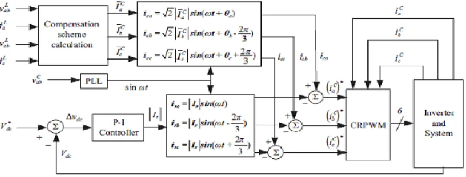
Figure 3. Closed Loop Control Diagram for DSTATCOM Controller
Figure 3 shows the block diagram of the proposed DSTATCOM controller. From the equations used for the DSTATCOM controller calculates the compensation current commands by using line-to-line voltages and line current. The instantaneous compensation currents are obtained with the aid of the synchronous signal sin wt via a PLL circuit. Additionally, the dc-link voltage is maintained by supplying a real part of compensation current |Ir| via a P-I controller.
L ca L bc L ab L ca L bc L bc L ab L ca L ab L c L b L aV
V
V
Y
Y
Y
Y
Y
Y
I
I
I
0
0
0
The paper employees a current-regulated PWM (CRPWM) inverter as the power stage of the proposed DSTATCOM. The CRPWM inverter uses the error signals from the comparison results of the reference signals and the actual compensation currents as the input. This generates the needed compensation current of the DSTATCOM for fast load compensation.
With the help of supply current in-phase (isadr, isbdr and iscdr) and quadrature phase components (isaqr, isbqr and iscqr), then computed the three-phase instantaneous reference supply currents (isar, isbr and iscr).
Isar = isadr + isaqr, isbr = isbdr + isbqr, iscr= iscdr +iscqr
The reference currents generated by the DSTATCOM is helps to provide the triggering pulses with the help of hysteresis controller.
3. DIESEL GENERATOR SET USING DSTATCOM
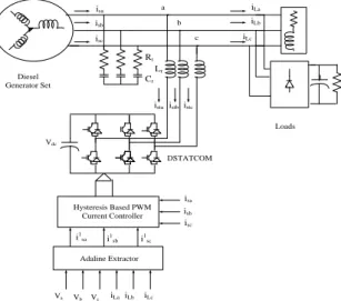
For distributing the power to some crucial equipment in remote areas the electrical energy produced by diesel engine-based unit plays an effective role. This type of distribution energy storage systems are loaded with unbalanced loads and non-linear loads. Due to this load variations causes the variations in power system parameters.
Figure 4 shows the schematic diagram for diesel energy system serves the different loads such as linear loads, non-linear loads etc.
Hysteresis Based PWM Current Controller Adaline Extractor DSTATCOM Loads Diesel Generator Set
Va Vb Vc
Vdc
iLaiLb iLc
isa isb isc iLa iLb iLc isa isc isb
istaistbistc
i1 sa i1
sb i1sc
Lr Rr Cr a b c
Figure 4. Configuration of Diesel Energy System Based Statcom Controller
4. FUZZY LOGIC CONTROLLER
Fuzzy controllers are directly using the fuzzy rules. The fuzzy inference engine system is a soft computational system which is used for analyzing the input variables in terms of logical variables i.e 0
&1.Logic involved in the fuzzy is dealing the concepts that which cannot be expressed as true or false. The Fuzzy Logic Controller main diagram is shown below.
e(t)
K1
K2
d/dt
F
u
zz
if
ic
at
io
n
Rule base
Inference mechanism
D
ef
u
zz
if
ic
at
io
n
K3 U(t)
Figure 5. Block diagram of Fuzzy Logic Controller
Three stages of Fuzzy controllers are output stage, processing stage, input stage. The input stage senses the input, processing stage generates result for each, and output stage combines the results and shows a final output value. For low cost implementation fuzzy logic is preferred
5. SIMULATION DIAGRAM AND WAVEFORMS
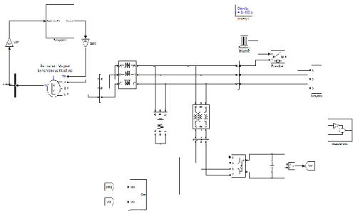
The experimental setup for the diesel generation system along with statcom controller is shown in Figure 6. Power System Block set and Simulink are used to modeling of the control diagram for main power circuit .Three-phase AC source represents the grid source and connected at the load end. DSTATCOM is a combination of voltage source converter fed capacitive reactor or distributed energy source.
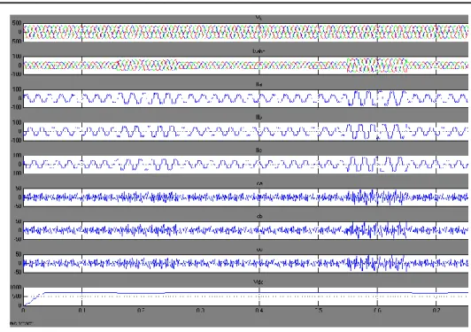
Figure 7. Simulation Results Non- Linear R-Load
The simulation diagram for the proposed diesel generation system with statcom controller is shown in Figure 7. Figure 7 shows the simulation result for output current, source currents, voltages and compensated currents of the proposed system.
The simulation result for RMS value of the line current is shown in Figure 8. And the line voltage RMS voltage is shown in Figure 9.
Figure 8. PCC Voltage without DSTATCOM during LG Fault
Table 1. Comparison of %Thd Values
TYPE Vs Is IL
PI 24.75 24.66 94.37 FUZZY 24.75 24.60 87.69 5. CONCLUSION
This paper proposed Fuzzy logic based static compensator for compensating the power quality problems in the distribution systems. The distribution static compensator is one of the type in most flexible device which is operated under voltage or current controlled modes, the current control mode is used for compensating voltage variations, unbalances and the voltage control modes is for voltage stabilizers. It has the capability for controlling the unbalances and variations in input currents. It is observed that with the help of these compensator the factor of total harmonic distributor is reduced. This paper is extended with the help of fuzzy logic controller. The main of this fuzzy controller is to reduce the settling time and also provides better control action. And also this fuzzy controller provides less total harmonic distortion as compared with the other conventional controllers.
REFERENCES
[1] IEEE Standard Criteria for Diesel-Generator Units Applied as Standby Power Supplies for Nuclear Power
Generating Stations. IEEE Std. 1996: 387-1995.
[2] B Singh, A Adya, AP Mittal, JRP Gupta. Performance of DSTATCOM for isolated small alternator feeding non-linear loads. in Proc. Int. Conf. Comput. Appl. Elect. Eng. Recent Adv. 2005: 211–216.
[3] [Online].Available:http://www.yamahageneratorstore.com/ef2800i.htm.
[4] E Acha, VG Agelidis, O Anaya-Lara, TJE Miller. Power Electronic Control in Electrical Systems. London, U.K.: Newnes. 2002.
[5] H Akagi, Y Kanazawa, A Nabae. Generalized theory of the instantaneous reactive power in three-phase circuits. in
Proc. IEEE IPEC, Tokyo, Japan. 1983: 821–827.
[6] A Chandra, B Singh, BN Singh, K Al-Haddad. An improved control algorithm of shunt active filter for voltage regulation, harmonic elimination, power-factor correction, and balancing of nonlinear loads. IEEE Trans. Power Electron. 2000; 15(3): 495–507.
[7] GD Marques. A comparison of active power filter control methods in unbalanced and non-sinusoidal conditions. in
Proc. IEEE Annu. Conf. Ind. Electron. Soc. 1998; 1: 444–449.
[8] J Nastran, R Cajhen, M Seliger, P Jereb. Active Power Filters for Nonlinear AC loads. IEEE Trans.on Power Electronics. 2004; 9(1): 92-96.
[9] LA Moran, JW Dixon, R Wallace. A Three Phase Active Power Filter with fixed Switching Frequency for Reactive
Power and Current Harmonics Compensation. IEEE Trans. On Industrial Electronics. 1995; 42(4): 402-8.
[10]LT Moran, PD Ziogas, G Joos. Analysis and Design of Three Phase Current source solid State Var Compensator,
IEEE Trans, on Industry Applications.
BIOGRAPHIES OF AUTHORS
Mr. Busi Jacob Prabhakar received his B.Tech degree in Electrical and Electronics Engineering from Sri Vani College of Engineering, Chevuturu, Vijayawada and he is pursuing M.Tech degree in Power Systems from K.L.University Vaddeswaram, Guntur .His area of intrest are power system Protection, machines, renewable energy systems, Distribution Systems and FACTS Controllers.
Mr. Srinivasarao Yelavarthi was born in 1984. He received the B.Tech. Degree in Electrical and Electronics Engineering (First class) from JNTU in 2006, and M.Tech. Degree in Computational Engineering & Networking (First class with distinction) from Amrita Vishwavidyapeetham in 2009. He is currently working as an assistant professor in KL University since 2011.and he is also pursuing PhD. His research interests Include Wavelets, Power System Protection, and FACTS.