i.LON
®
100 e3 User’s Guide
@
®Echelon, LONWORKS, LonTalk, Neuron, LONMARK, LonScanner
and the Echelon logo are trademarks of Echelon Corporation registered in the United States and other
countries. LonMaker is a trademark of Echelon Corporation. Other brand and product names are trademarks or registered trademarks of their respective holders.
NeuronChips and other OEM Products were not designed for use in equipment or systems which involve danger to human health or safety or a risk of property damage and Echelon assumes no responsibility or liability for use of the NeuronChips in such applications.
Parts manufactured by vendors other than Echelon and referenced in this document have been described for illustrative purposes only, and may not have been tested by Echelon. It is the responsibility of the customer to determine the suitability of these parts for each application.
ECHELON MAKES AND YOU RECEIVE NO WARRANTIES OR CONDITIONS, EXPRESS, IMPLIED, STATUTORY OR IN ANY COMMUNICATION WITH YOU, AND ECHELON SPECIFICALLY DISCLAIMS ANY IMPLIED WARRANTY OF MERCHANTABILITY OR FITNESS FOR A PARTICULAR PURPOSE.
No part of this publication may be reproduced, stored in a retrieval system, or transmitted, in any form or by any means, electronic, mechanical, photocopying, recording, or
otherwise, without the prior written permission of Echelon Corporation.
Printed in the United States of America. Copyright © 2002-2006 Echelon Corporation. www.echelon.com
i.LON 100 e3 User’s Guide i
Welcome
This document describes how to configure the i.LON 100 e3 Internet Server, and how to use its applications in control and data networks.
Related Documentation
The documentation for the i.LON 100 server is provided as online Adobe Acrobat PDF files and Windows help files. The i.LON 100 documentation consists of the following manuals:
• i.LON 100 e3 Hardware Guide— Describes how to assemble and wire the i.LON 100 server hardware.
• i.LON 100 e3 Programmer’s Reference—Describes how to configure the i.LON 100 using XML files and SOAP calls. This allows you to create your own applications you can use to configure the i.LON 100 server.
• IP-852 Channel User’s Guide—Describes how to configure an IP-852 channel with the Echelon LONWORKS®/IP Configuration Server. You will need this
information if you plan to use the i.LON 100 server as an IP-852 router. The following additional documents may be useful if you are using certain features of the i.LON 100. You can download these documents from Echelon’s Web site at www.echelon.com.
• LonMaker® User’s Guide—Describes how to use the LonMaker tool, which
can be used to install the i.LON 100 server in a LONWORKS network. • LNS® Programmer’s Guide—Describes how to write LNS applications that
can take advantage of the communication provided by the i.LON 100 server.
• OpenLDV™ Programmer’s Guide, xDriver Supplement — Describes how the
xDriver software can be used by an LNS or OpenLDV application to manage communications with multiple LONWORKS networks over a TCP/IP network.
The xDriver software is used to communicate with the i.LON 100 server when it is functioning as a Remote Network Interface (RNI).
What’s Included with the
i.
LON 100 Server
The i.LON 100 server includes the following components:
• i.LON 100 Device—There are eight models of the i.LON 100 Internet Server. There are versions for TP/FT-10 free topology and PL-20 power line; versions with or without a built-in analog modem; and versions with or without IP-852 routing enabled. You can also purchase an IP-852 activation key for i.LON 100 e3 servers that do not already have IP-852 routing enabled. The inputs and outputs of each model are slightly different, as noted in the i.LON 100 e3 Hardware Guide.
• i.LON 100 Quick Start Guide — This document describes how to connect the i.LON 100 hardware, and how to configure the i.LON 100’s IP information using the i.LON 100 Web pages.
• i.LON 100 CD — This CD contains the installation software for the i.LON 100 server, as well as the installation software for LNS 3 Service Pack 7, Update 1, and LonMaker 3.1 Service Pack 2, Update 1.
Hardware Requirements
Hardware requirements and recommendations for the computer running the i.LON 100 software are listed below:
• Pentium II 600 MHz or faster
• 128-MB RAM minimum
• 70 MB free hard disk space
• CD-ROM drive
• Super VGA (800 × 600) or higher-resolution display with 256 colors
• Mouse or compatible pointing device
Software Requirements
Software requirements for computers running the i.LON 100 software are listed below:
• Microsoft® Windows® XP, Windows 2000, or Windows Server 2003. Echelon recommends that you install the latest service pack available from Microsoft for your version of Windows. Screen resolution 1024x768 with large or small fonts; 800x600 with small fonts only.
• LonMaker 3.1, Service Pack 2 or better and/or LNS 3.1, Service Pack 8, Update 1 or better.
• Internet Explorer 6 or higher.
• Terminal emulator, such as Windows HyperTerminal
Table of Contents
Welcome...i
Related Documentation ...i
What’s Included with the i.LON 100 Server ...i
Hardware Requirements ...ii
Software Requirements ...ii
Table of Contents ...ii
Introduction 1 Introduction... 2
What’s New in e3 ... 2
i.LON 100 Internet Server Applications ... 3
i.LON 100 System Limits ... 4
i.LON 100 RNI Limits... 4
i.LON 100 Application Limits... 5
i.LON 100 e3 User’s Guide iii
Configuring the i.LON 100 Internet Server 9 Installing the i.LON 100 Software... 10
Connecting and Configuring the i.LON 100 Internet Server... 12
Setting Up Connections, Servers, and Services... 14
Configuring General LAN/WAN Properties... 15
Configuring LAN Connection Properties... 16
Creating and Configuring a Dial-up Connection ... 18
Creating and Configuring Servers... 22
Creating and Configuring Services... 23
Verifying i.LON 100 Connections ... 29
Configuring Modem Settings ... 29
Configuring LONWORKS Settings ... 33
Configuring LonTalk Properties ... 35
Configuring NVE Driver Properties ... 35
Configuring LNS Uplink/Downlink Properties... 37
Configuring Initiate LNS Uplink Properties ... 38
Configuring IP-852 Router Properties ... 38
Configuring Time Settings and the Astronomic Position Sensor... 39
Elevation and Azimuth... 40
Configuring the M-Bus Driver... 41
Configuring the Modbus Driver... 43
Adding Modbus Devices from Templates ... 49
Upgrading the i.LON 100 Firmware ... 49
Performing the Upgrade ... 50
Upgrading the i.LON 100 Device ... 54
Converting an e3 Server to Release 1 or e2... 55
i.LON 100 Server Security ... 55
Security Access Reset... 56
i.LON 100 Security Web Page ... 57
Configuring the i.LON 100 Applications 61 Configuration Plug-In / Web Page Overview ... 62
Getting Started With the i.LON 100 Web Pages ... 62
Getting Started With the Configuration Plug-In... 63
The i.LON 100 Shapes Stencil... 64
Adding an i.LON 100 Shape to a LonMaker Drawing ... 64
Adding i.LON 100 Functional Blocks to a LonMaker Drawing ... 65
Starting the Plug-in... 65
Creating Data Points 67 Data Points... 68
Data Point Types ... 68
Data Point Presets... 69
Data Points and the i.LON 100 Web Pages... 70
Reading and Writing Data Point Values ... 70
Modifying the Data Point Tree... 71
Configuring Data Points ... 72
Adding and Removing Presets... 74
Data Points and the i.LON 100 Configuration Plug-In... 75
Creating and Viewing Local Data Points (NVLs)... 75
Network Variable Programmatic Names ... 76
Creating and Viewing External Data Points (NVEs)... 77
Creating Data Point Presets... 81
Alarming 83 Alarming Overview ... 84
Alarm Generator... 84
Alarm Notifier... 85
Alarming with the i.LON 100 Web Pages ... 85
Configuring an Alarm Generator ... 86
Providing an Alarm Notification ... 91
Viewing the Alarm Summary and Alarm History Logs... 98
View - Alarm Summary Web Page... 98
View - Alarm History Web Page ... 100
Scheduling 103 Scheduling Overview ... 104
Creating a Schedule... 104
Planning Out Your Schedule ... 105
Example of Planning Out a Schedule ... 105
Creating an Event Scheduler with the i.LON 100 Web Pages ... 105
Adding Data Points to an Event Scheduler ... 106
Setting the Daily Schedule ... 108
Adding Exceptions to the Daily Schedule ... 110
Creating Recurring Exceptions... 112
Using the Configure – Event Scheduler – Calendar Exceptions Web Page ... 117
Viewing Event Schedulers ... 120
Logging Data 121 Data Logger Overview ... 122
Creating a Data Logger with the i.LON 100 Web Pages... 122
Extracting Data Logs ... 126
Viewing Data Logs... 126
Using a Data Logger with an Alarm Notifier... 127
Using Pulse Counter Inputs 129 Pulse Counter Overview ... 130
Using the Pulse Counter with the i.LON 100 Web Pages... 130
Using Digital Inputs/Digital Outputs 133 Overview ... 134
Using Digital Inputs With the i.LON 100 Web Pages... 134
Using a Digital Output With the i.LON 100 Web Pages... 135
Web Binding 137 Using Web Connections ... 138
Configuring Internet Explorer for Web Binding ... 139
Creating a Web Connection ... 139
Retrieving File Attachments... 143
Type Translators and Analog Function Blocks 145 Type Translator... 146
Using the Type Translator Functional Block ... 146
Creating a Custom Type Translator Rule... 148
Integrating M-Bus Devices With a Type Translator... 151
i.LON 100 e3 User’s Guide v
Step 2: Evaluating the device specification... 151
Step 3: Modifying the M-Bus Type Translator Rules ... 152
Step 4: Using the M-Bus Type Translator Shapes in LonMaker154 Analog Function Block... 155
Using the Analog Function Block... 156
Adding, Averaging, or Selecting the Minimum or Maximum of Two or More Values... 157
Comparing Data Points... 160
Sending ANSI/CEA-709.1 Packets Over IP with the i.LON 100 Server 163 Overview ... 164
Using the i.LON 100 Server as an RNI ... 167
Using the LONWORKS Interfaces Application ... 168
Switching Between the i.LON 100 RNI and a Standard LONWORKS Network Interface ... 172
Using the i.LON 100 Server as an IP-852 Router ... 172
Activating and Configuring the IP-852 Router ... 172
Creating an i.LON 100 Web Page 175 Introduction... 176
Creating a Simple Web Page... 176
Advanced Web Page Creation ... 189
Introduction to the i.LON Vision Framework ... 189
i.LON 100 Demo Web Pages ... 191
Step One: Create a Connection to the i.LON 100 Server... 192
Step Two: Create a User Directory and the Start.htm File... 195
Step Three: Customize the Login Web Page... 199
Step Four: Create Custom i.LON 100 Web Pages... 202
Using i.LON Vision Objects... 204
Data Point Status and Priority Icons ... 223
Copying and Pasting i.LON Vision Objects... 227
Contribute Image Menu Graphics ... 228
Step Five: Defining the Default Page for Your Web Site... 229
Step Six: Creating a Menu For Your Web Pages... 231
Using the Menu Edit Dialog... 233
Step Seven: Creating a Sidebar For Your Web Pages... 236
Tutorial: Using Data Point Substitution Tags... 238
Adding Security to Your Custom Web Pages ... 246
Customizing the Demo Area... 246
Using i.LON Vision While Offline... 246
Troubleshooting Web Page Designs... 247
Using Other Tools To Build i.LON 100 Web Pages ... 249
Troubleshooting 251 Troubleshooting... 252
Managing the i.LON 100 Server 255 Rebooting the i.LON 100 Server ... 256
Restoring Factory Defaults to the i.LON 100 Server ... 256
Viewing i.LON 100 System Information ... 257
i.LON 100 Model Information... 258
i.LON 100 Flash Information ... 259
Backing Up and Restoring the i.LON 100 Server... 261
Backing Up With the Configuration Plug-In... 262
Restoring or Duplicating an i.LON 100 Server ... 264
Replacing an i.LON 100 Server ... 264
i.LON 100 Console Application 267 Using the Console Application ... 268
Console Command List ... 268
Interrupting the Boot Process ... 274
The Bootrom State... 274
Updating the Bootrom... 275
Web Server Parameters Utility 277 Overview of i.LON 100 User Web Page Security... 278
Setting Access Restrictions ... 279
Users and Groups... 279
Locations... 281
Realms ... 282
Aliases... 283
Parameters ... 283
Sample WebParams.dat file ... 284
Creating a Web Page Using Web Tags 287 Overview of Creating i.LON 100 Web Pages Using Web Tags ... 288
Using the i.LON 100 Server’s Web Server ... 288
Required Hardware ... 288
Required Software ... 288
Creating The LonMaker Network ... 289
Creating Web Pages ... 289
How the HTML Code Works... 291
Using The Web Server Functional Block ... 293
Required Hardware ... 293
Required Software ... 293
Setting Up The Hardware... 293
Creating the LonMaker Network ... 293
Creating Web Pages ... 296
<iLonWeb> Web Tag Format ... 298
FUNC Attribute... 299
Func=ShowValue ... 299
FUNC=Include ... 299
FUNC=CreateSymbol ... 300
SYMBOL Attribute... 300
Data Point Symbols (NVL_, NVE_, and NVC_ Prefixes) ... 301
System Symbols (ILON_ Prefix) ... 303
Web Tag Attributes ... 306
FIELD:... 307
FORMAT: ... 307
Standard Resource File Set... 307
User Resource File Sets... 307
Built-in Formats... 308
PROPAGATE: ... 308
WAIT: ... 309
Working with Forms ... 309
Opening a Form ... 309
i.LON 100 e3 User’s Guide vii
Refresh a Form ... 311
Form Element Functions ... 311
CheckBox ... 311
Hidden ... 312
RadioButton ... 312
TextField... 313
i.LON 100 Software License Agreement 315 Software License Transfer Agreement 321 Software License Transfer Agreement ... 322
i.LON 100 e3 User’s Guide 1
1
Introduction
This chapter provides an introduction to the i.LON 100 server and its applications, as well as a roadmap to follow to get started with the i.LON 100 server.
Introduction
Thei.LON 100 e3 Internet Server is a low-cost, high-performance network interface, controller, router, and Web server that connects LONWORKS, M-Bus,
and Modbus devices to corporate IP networks or the Internet. The i.LON 100 server features a built-in Web server that allows Web access to all the data managed by the i.LON 100 server, as well as built-in applications for alarming, scheduling, and data logging. Additionally, it includes a Web binder for bridging multiple LONWORKS domains, and it provides a SOAP/XML Web services
interface for use by custom Web pages and for integration with enterprise
applications. An IP-852 routing option is available, that can be ordered with new units or purchased for e3 units without routing. The i.LON server operates on 100 – 240 VAC and can be ordered with an optional built-in 56K V.90 analog modem. Models are available for TP/FT-10 channels and PL-20 channels. The i.LON 100 server also includes built-in I/O for reading pulse meters and digital inputs, and for switching local loads. All data points and built-in I/O is accessible through either the LONWORKS or Web interfaces. The i.LON 100
server can be used as a Remote Network Interface (RNI), allowing remote access to the entire LONWORKS network using LNS or OpenLDV based tools, including
the LonMaker® Integration Tool. It can also be used with the LonScanner™
Protocol Analyzer to capture, analyze, characterize, and display ANSI/CEA-709.1 network packets either locally or remotely via the Internet.
What’s New in
e3
The e3 release of the i.LON 100 Internet Server includes the following new features:
• The i.LON Vision software, which works with Macromedia Contribute 3.1 to allow easy and efficient creation of custom i.LON 100 Web pages for creating custom monitoring and control solutions with the i.LON 100 server. You can create custom Web pages to read or write data points or view log files. i.LON Vision is described in Chapter 13, Creating an i.LON 100 Web Page.
• A new IP-852 ANSI/CEA-709.1-to-IP routing option that allow you to use the i.LON 100 server as a router on an IP-852 channel. The initial steps required to configure the i.LON 100 server as an IP-852 router are described in
Chapter 12, Sending ANSI/CEA-709.1 Packets Over IP with the i.LON 100 Server. The IP-852 Channel User’s Guide document included with the i.LON 100 software provides background information you will need when designing the IP-852 network and using the i.LON 100 server as an IP-852 router.
• Web Binder file attachment. You can send a file with a Web connection update. This make it easy to get data logs from an i.LON 100 server behind a firewall to a monitoring system outside the firewall. This feature is described in Chapter 10, Web Binding.
• Improved alarming and scheduling interfaces. The scheduling and alarming application Web pages have been updated to allow easier, quicker creation of Alarm Generators, Alarm Notifiers, and Event Schedulers. These features are described in Chapter 5, Alarming, and Chapter 6, Scheduling.
i.LON 100 e3 User’s Guide 3
• Data Logger file compression. You can now store the CSV-formatted historical log files generated by the Data Logger application in compressed format, saving flash memory space on the i.LON 100 server and reducing connection time when transferring data logs through a dial-up connection. This feature is described in Chapter 7, Logging Data.
• Modbus driver interface. You can monitor and control Modbus devices attached to an i.LON 100 server. The steps required to configure Modbus server and create Modbus data points to use with the i.LON 100 server are described in Chapter 2, Configuring the i.LON 100 Internet Server.
• Astronomical Position Sensor. You can calculate the position of the sun based on your location and time-of-day. This is useful for calculating whether it is light or dark outside without using an external light-level sensor. This is used in applications such as street lighting, where lights need to come on at dusk and go off at sunrise. This feature is described in Chapter 2,
Configuring the i.LON 100 Internet Server.
• Dynamic DNS support. Dynamic DNS allows for an Internet hostname to be assigned to a device with a varying IP address. Because the i.LON 100 server can be accessed from a known, non-changing hostname, it is possible for a Web service or user to access the i.LON 100 server without needing to track the time-varying IP address. This feature is described in Chapter 2, Configuring the i.LON 100 Internet Server.
• Support for LonScanner Protocol Analyzer access. You can use the Echelon’s LonScanner Protocol Analyzer to monitor the traffic on the channel connected to the i.LON 100 server and diagnose network problems. For more
information on using the i.LON 100 server with the protocol analyzer, see the LonScanner Protocol Analyzer User’s Guide.
i.
LON 100 Internet Server Applications
The i.LON 100 Internet Server provides the following capabilities, in addition to the new features described in the previous section:
• Alarming—The i.LON 100 server can trigger alarms based on inputs from the devices it is attached to. In response to an alarm condition, the i.LON 100 server can be configured to update any data point including a data point for a network variable in a LONWORKS device, Modbus device, or M-Bus
device, or a data point in a Web page; log the conditions to one or more data logs; or send out emails or SOAP messages notifying recipients of the alarms and the conditions that triggered them. Alarms can be configured to shut off automatically when certain conditions are met or they can be configured to require manual clearance via a Web page.
• Data Logging—The i.LON 100 server can log any data point including a data point for a network variable in a LONWORKS device, Modbus device, or M-Bus
device. These logs can be downloaded using the Internet File Transfer Protocol (FTP), retrieved using a SOAP/XML Web service, or displayed with the i.LON 100 Web pages.
• Scheduling—The i.LON 100 server can be used to update any data points based on the time-of-day, day-of-week, and date. These schedules can drive
the inputs to any data point including a data point for a network variable in a LONWORKS device, Modbus device, or M-Bus device.
• Digital Input/Output—The i.LON 100 server contains 2 built-in digital inputs and 2 built-in digital relay outputs. These can be used to monitor and control simple sensors and actuators.
• Type Translation—The i.LON 100 server can translate data from one data type to another. This is useful for integrating disparate devices, including devices on different networks and busses. For example, this can be used to connect an output on an LONWORKS device to an input on a Modbus device—
even the data types of the two data points are different.
• Pulse Metering—The i.LON 100 server contains two built-in pulse metering inputs. You can configure the i.LON 100 server to count pulses or to measure the pulse frequency from pulse output devices.
• Analog Function Processing—The i.LON 100 server contains an Analog Function Block application that you can use to perform operations on multiple analog inputs.
• Remote Network Interface—The i.LON 100 server can operate as a Remote Network Interface (RNI), allowing you to use it to connect an LNS or OpenLDV application on an IP network to a LONWORKS network. • Dial-in/Dial-out Support—The i.LON 100 server can optionally contain a
built-in modem. On these models you can configure the i.LON 100 server to dial-out and receive calls using the Internet Point-to-Point (PPP)
communications protocol.
i.
LON 100 System Limits
The following sections document the limits of the i.LON 100 RNI capabilities and of the applications that run on the i.LON 100 server.
i.LON 100 RNI Limits
The capabilities of the RNI on the i.LON 100 server are largely dependent on the software running on the host computer. When used as an LNS network
interface, the i.LON 100 server has the following limits. See the Introduction to LonWorks document or the LonMaker User’s Guide for more information about these limits:
• Up to 32768 address table entries.
• Up to 15 simultaneous outgoing transactions.
• Up to 1024 aliases.
• Up to 256 groups, with up to 15 used for incoming messages.
• Up to 4096 dynamic network variables.
• Output messages can be sent to up to 256 different destination addresses within each 24 second interval. Multiple messages can be sent to each of those destination addresses within the interval.
i.LON 100 e3 User’s Guide 5
i.LON 100 Application Limits
The i.LON 100 application has the following limits:
• Up to 4096 address table entries.
• Up to 32 simultaneous outgoing transactions.
• Up to 1024 aliases.
• The i.LON 100 application can support up to 3000 dynamic network
variables, but the i.LON 100 server will run out of memory before this limit is reached; the practical limit depends on the sizes of the defined dynamic network variables. You can check the available memory on the System Info Web page.
Getting Started
When you begin using the i.LON 100 server, follow these steps:
1. Install the i.LON 100 software and perform the initial setup and configuration tasks described in Chapter 2, Configuring the i.LON 100 Internet Server.
2. Start the i.LON 100 Web pages, or the i.LON 100 Configuration Plug-In. These tasks are described in Chapter 3, Configuring the i.LON 100 Applications.
3. Create the data points for the devices you want to use with the i.LON 100 server have been created. For more information on data points, see Chapter 4, Creating Data Points.
4. Configure the applications you want to use. Chapters 5-12 of this document describe the various applications of the i.LON 100 server. 5. Create custom Web pages for monitoring and controlling your devices.
You can use i.LON Vision to create custom Web pages as described in Chapter 13, Creating an i.LON 100 Web Page.
Table 1.1 describes the remaining chapters of this document in more detail. Table 1.1 Document Roadmap
Chapter Description Chapter 2, Configuring
the i.LON 100 Internet Server
Describes how to install the i.LON 100 software and the initial steps you should take to configure the i.LON 100 server before using any of its applications. This chapter also describes how to upgrade an i.LON 100 server running on the previous version of the i.LON 100 software to e3.
Chapter Description Chapter 3, Configuring
the i.LON 100 Applications
Provides an overview of the tools you can use to configure the i.LON 100 server: i.LON 100 Web pages and the i.LON 100 Configuration Plug-In. You should use the Web pages to configure your i.LON 100 server whenever possible. However, there are some cases where you might need to use the
Configuration Plug-In. This chapter describes those situations. Chapter 4, Creating
Data Points This chapter describes how to create data points you can use to monitor and control the devices on your network with the various applications of the i.LON 100 server.
Chapter 5, Alarming This chapter describes how to use the i.LON 100 alarming applications. This includes the Alarm Generator functional block, which you can use to generate alarms based on monitored conditions, and the Alarm Notifier functional block, which you can use to send emails and update data points based on alarm conditions.
Chapter 6, Scheduling This chapter describes how to use the i.LON 100 scheduling applications to create an Event Scheduler. You can use Event Schedulers to schedule daily, weekly and monthly updates to the data points on your network.
Chapter 7, Logging Data This chapter describes how to use the Data Logger application to save network data in logs files, and how to view the logs.
Chapter 8, Using Pulse
Counter Inputs This chapter describes how to use the i.LON 100 server’s Pulse Counter to measure electrical energy, volume, rate or flow, or power.
Chapter 9, Using Digital
Inputs/Digital Outputs This chapter describes how to use the i.LON 100 server’s two digital inputs and two digital outputs Chapter 10, Web
Binding This chapter describes how to create Web connections with the i.LON 100 server. Web Binding is a process by which you can connect data points on your i.LON 100 server directly to data points on another i.LON 100 server or to a third party Web service application or Web server such as Apache or IIS, and keep the values of those data points synchronized.
Chapter 11, Type Translators and Analog Function Blocks
This chapter describes the Type Translator and Analog Function Block applications. You can configure these applications with the Configuration Plug-In, but not with the i.LON 100 Web pages.
i.LON 100 e3 User’s Guide 7
Chapter Description Chapter 12, Sending
ANSI/CEA-709.1 Packets Over IP with the i.LON 100 Server
This chapter describes how to configure the i.LON 100 server as a remote network interface (RNI), which allows you to use the i.LON 100 server as a LONWORKS network interface, and
connect to an LNS or OpenLDV application, and how to configure the i.LON 100 server as an IP-852 router. Chapter 13, Creating an
i.LON 100 Web Page This chapter describes how to create custom Web pages for the i.LON 100 server using i.LON Vision and Macromedia Contribute.
Appendix A,
Troubleshooting This appendix describes how to diagnose and resolve problems that may occur during the installation and operation of the i.LON 100 server.
Appendix B, Managing
the i.LON 100 Server This appendix describes how to reboot the i.LON 100 server, how to restore the default manufacturer settings to the i.LON 100 server, how to view i.LON 100 system information, and how to backup and restore the configuration of the i.LON 100 server. Appendix C, i.LON 100
Console Application This chapter describes how to use the i.LON 100 server’s console application, which you can use to reboot the i.LON 100 server and perform other tasks that may be necessary, such as
updating the bootrom. Appendix D, Web Server
Parameters Utility This appendix describes how to use the i.LON 100 Web Server Parameters utility to add security to your custom Web pages. Appendix E, Creating a
Web Page Using Web Tags
This appendix demonstrates how to create Web pages that serve Web page values using web tags. You should use the i.LON Vision software to create Web pages for the i.LON 100 server, since web tags will not be supported in future releases of the i.LON 100.
Appendix F, i.LON 100 Software License Agreement
This appendix includes the software license agreement for the i.LON 100 e3 software.
Appendix G, Software License Transfer Agreement
This appendix includes an agreement that you can use to transfer an i.LON 100 software license to another organization.
i.LON 100 e3 User’s Guide 9
2
Configuring the
i.
LON 100
Internet Server
This chapter describes how to install the i.LON 100 e3 software, and the initial steps you should take to configure the i.LON 100 server before using any of its applications. It also describes how to upgrade an i.LON 100 server running the Release 1 or e2 software to use the e3 software.
Installing the
i.
LON 100 Software
To use the i.LON 100 Configuration Plug-in, you must install the i.LON 100 software. Follow the steps below to install the i.LON 100 software. Note that in order to access the i.LON 100 Web pages, you must have Internet Explorer 6 or later.
1. If you are using an LNS application, verify that you have LNS 3 SP 8 Update 1 (orlater). If you are using the LonMaker Integration Tool, verify that you have LonMaker 3.1 SP3 Update 2 (or later). These patches are available on the i.LON 100 CD-ROM, in the following locations: LNS 3 SP8 \LNS SP8 xDriver\Lns3sp8_5a.exe
LNS 3 SP8 Update 1 \LNS SP8 xDriver\Lns3sp8u1.exe
LonMaker 3.1 SP3 \LMW 3.1 SP3\lmw313.exe
LonMaker 3.1 SP3 Update 1 \LMW 3.1 SP3\lmw313U1.exe
LonMaker 3.1 SP3 Update 2 See step 3.
These patches must be installed in the order they are listed above. If you have a version of the LonMaker tool prior to Release 3.1 you must first update to LonMaker 3.1. This will bring your computer up to the latest revisions of LonMaker and LNS software. The latest service packs for LNS and the LonMaker tool are available at
www.echelon.com/downloads. You can also install LonMaker 3.1 Service Pack 3 Update 2 from the main installation window described in step 3 of this procedure.
You can verify that you have the correct versions of all software installed by clicking on the LonMaker Design Manager's title bar and selecting About Echelon LonMaker. This dialog should appear as shown in Figure 2.1.
i.LON 100 e3 User’s Guide 11 Figure 2.1 LonMaker Network Integration Tool Dialog
2. Verify that you have Internet Explorer 6, SP 1 (or later) installed on your computer. You can install Internet Explorer 6, SP 1 from the main installation window described in steps 3 and 4 of this procedure.
3. Insert the i.LON 100 e3 CD. The i.LON 100 e3 window should appear. If it does not, open the root directory of the i.LON 100 CD and double-click
Setup.exe.
4. Click Install Products to open the Install Products window.
5. To install the i.LON 100 software, select Echelon i.LON 100 e3 Software and then follow the on-screen installation prompts to install the i.LON 100 software.
6. If you plan to use the i.LON Vision software to create custom Web pages for your i.LON 100 server, you need to have Macromedia Contribute 3.1 installed on your computer. You can select Macromedia Contribute 3.1 Trial Version to install a trial version of the software. Then, select Echelon i.LON Vision Software and follow the instruction prompts to complete the installation. You must install Macromedia Contribute 3.1 before installing the i.LON Vision software. You can install the i.LON Vision software later if you will be acquiring Macromedia Contribute from another source.
Connecting and Configuring the
i.
LON 100
Internet Server
After you install the i.LON 100 software on your computer, you will connect to the i.LON 100 server and perform some initial configuration tasks. To do so, follow these steps:
1. Assemble the i.LON 100 server, as described in the i.LON e2 Hardware Guide.
2. If you are upgrading an i.LON 100 server running on a previous version of the i.LON 100 software, upgrade the i.LON 100 server’s firmware with the upgrade wizard, as described in the Upgrading the i.LON 100
Firmware section on page 49. This will allow you to use the new e3 Web pages and Plug-In features.
3. If your computer is not on the same subnet as the i.LON 100 server (192.168.1.x be default), then open a Windows command prompt on your computer and issue the following command before accessing the Welcome Web page (change “192.168.1” to the appropriate prefix for your subnet): route add 192.168.1.0 mask 255.255.255.0 %computername%
4. Open Internet Explorer 6 and enter the address of your i.LON 100 server. By default, this is http://192.168.1.222, but you may have changed that if you are upgrading an existing i.LON 100 server. The i.LON 100 Internet Server Welcome Web page appears.
5. Click Service. You will be prompted for a user name and password. Enter your user name and password, which by default are ilon/ilon.
i.LON 100 e3 User’s Guide 13 Figure 2.2 i.LON 100 Internet Server Welcome Web Page 6. Use the Network - LAN/WAN Web page to set up the i.LON 100 server’s
connections, servers, and services. For more information on the Network - LAN/WAN Web page, see the Setting Up Connections, Servers, and Services section on page 14.
7. If your i.LON 100 server is equipped with a modem, configure the modem with the Configure - Modem Web page. For more information on the Configure - Modem Web page, see the Configuring Modem Settings section on page 29.
8. Configure the LONWORKS settings for the i.LON 100 server with the
Network - LONWORKS Web Page. You will need to configure these
settings if you plan to use the i.LON 100 server as an RNI to connect an LNS or OpenLDV-based application to the LONWORKS network. You can
also use this Web page to configure the NVE driver, which manages the NVE (external) data points on the network. NVE data points are data points on other devices on the network. The i.LON 100 server can use NVE data points to monitor those devices. For more information on this Web page, see the Configuring LONWORKS Settings section on page 33.
9. If you plan to use the i.LON 100 server as a router on an IP-852 channel, activate the router option and then configure the i.LON 100 server’s IP-852 router settings. For more information on this, see the Configuring IP-852 Router Properties section on page 38.
10. Configure the i.LON 100 server’s time settings, as described in the Configuring Time Settings section on page 39.
11. Configure the M-Bus and Modbus drivers with the Network - M-Bus and Network - Modbus Web pages. These tasks are described in detail in the Configuring the M-Bus Driver and Configuring the Modbus Driver sections later in this chapter.
12. Optionally, perform a security access reset on the i.LON 100 server and set the i.LON 100 server’s security options. For more information, see the i.LON 100 Server Security section on page 55.
13. Reboot the i.LON 100 server. To do so, point to Setup, and then click Reboot on the menu to open the Setup - Reboot Web page. Click the Reboot button to reboot the i.LON 100 server. Once the i.LON 100 server has been rebooted, the new configuration settings will take effect.
Setting Up Connections, Servers, and Services
You can manage the connections, servers, and services used by the i.LON 100 with the Network - LAN/WAN Web page. Figure 2.3 shows the Network – LAN/WAN Web page.
Figure 2.3 LAN/WAN Web Page
The connections tree on the left-hand side of the Web page shows the
connections, servers and services that are currently defined on the i.LON 100 server. The top level of the tree shows i.LON 100 connections. These connections define how the i.LON 100 server communicates with other devices. The i.LON 100 server supports two types of connections:
• LAN Connection – The LAN connection corresponds to the i.LON 100 server’s 10/100-BaseT Ethernet connection. This connection is always the first connection shown in the tree, and may not be removed.
• Dial-up Connections – The i.LON 100 server may contain any number of dialup connections below the LAN connection. Each dialup connection corresponds to an ISP. By default, the i.LON 100 server contains two sample dialup connections: Freenet and T-Online. It is good practice to delete unused connections and services that are provided as examples if they are not being used.
Each connection can have one or more servers. By default, the LAN connection has a server named Turnaround Address. The Turnaround Address server refers to the i.LON 100 server, and supports only the Web Binder service. For more information on the Web Binder application, see Chapter 10, Web Binding. Each server can have one or more services that are available from the server. Each server can support one or more of the following services:
• Email (SMTP) – This service is used to send email from the i.LON 100 server.
i.LON 100 e3 User’s Guide 15
• Web Binder – This service is used to bind the i.LON 100 server to another server.
• LNS Uplink – This service is used to communicate with an LNS Server.
• Time (SNTP) – This service is used to synchronize the time and date of the i.LON 100 server with a time server on the network.
• IP-852 – This optional service is used to connect the i.LON 100 server to an IP-852 channel.
The following sections describe how to open the LAN/WAN Web page, and begin configuring the connections, servers and services on your i.LON 100 server.
Configuring General LAN/WAN Properties
To configure general LAN/WAN properties such as the IP address and host name of the i.LON 100, follow these steps:1. Point your mouse cursor to Network, and then select LAN/WAN from the drop-down menu. This opens the Network - LAN/WAN Web page.
Figure 2.4 Network - LAN/WAN Web Page
2. Make sure the top level of the connections tree is selected, and then configure the properties on the Web page. Note that all fields marked with an asterisk on the Web page require a reboot for the new values to take effect. Table 2.1 describes the properties on the Network -
LAN/WAN Web page.
Table 2.1 General LAN/WAN Properties
Property Description LAN IP Address Displays the IP address of the i.LON 100 server used by the
Ethernet LAN connection. Click Configure to change this address. See the Configuring LAN Connection Properties section below for more information on this.
Dial-in IP Address Displays the IP address of the i.LON 100 server used when the i.LON 100 receives a phone call via the internal modem. Click Configure to change this address. See the Configuring LAN Connection Properties section below for more information on this.
Property Description GPRS Network IP Address Displays the IP address used by the i.LON 100 server when it is
connected via GPRS modem. If the i.LON 100 does not currently have a GPRS connection, this property displays Not Connected. Host Name Displays the TCP/IP host name of the i.LON 100 server. When the
i.LON 100 server establishes a connection with an LNS Server, it provides its fully qualified host/domain name so the LNS Server knows which LONWORKS database to open.
By default, the i.LON 100 server’s host name is iLON100. The URL
of the i.LON 100 server is the host name followed by the DNS suffix. For example, if the host name is ilon100Alpha and the domain suffix is ABCcorp.com, the URL would be
ilon100Alpha.ABCcorp.com.
Set a unique host name if you want to have the DHCP server register the host name with the DNS server, or when you want to manually register with the DNS server administrator.
Valid characters are numbers, letters, and the hyphen (‘-’) character. This field has a maximum length of 19 characters. If you change the host name, you must reboot the i.LON 100 server for the change to take effect.
Domain Suffix The IP domain name in which the i.LON 100 server’s Ethernet Adapter is installed. This value is optional. Valid characters are numbers, letters, and the hyphen (‘-’) and period (‘.’) characters. This field has a maximum length of 132 characters.
If the Automatically Obtain IP Address check box is selected on the Setup - LAN/WAN Web page (as described in the Configuring LAN Connection Properties section below), select the Obtain
Automatically From LAN check box to obtain the domain suffix from the DHCP server. By default, this value is cleared. If you change this value, you must reboot the i.LON 100 server for the change to take effect.
3. When you have finished setting the properties on the LAN/WAN Web page, click Submit to save the changes you have made to this Web page. Click Reset to leave all fields unchanged.
Configuring LAN Connection Properties
If you are connecting your i.LON 100 server directly to a TCP/IP network via the Ethernet port, you must configure the LAN connection properties on the Setup - LAN/WAN page. To do so, follow these steps:1. Point your mouse cursor to Setup, and then select TCP/IP from the dropdown menu. The Setup - LAN/WAN Web page will open with the LAN connection selected in the tree, as shown in Figure 2.5.
i.LON 100 e3 User’s Guide 17 Figure 2.5 Setup – LAN/WAN Web Page
2. Configure the properties on the Web page. Note that all fields marked with an asterisk require a reboot before the new values will take effect. Table 2.2 describes the properties on the Web page.
Table 2.2 LAN/WAN Connection Properties
Property Description Automatically Obtain IP Address Set this option to have the i.LON 100 server obtain its IP
address, subnet mask, and default gateway from the local network’s DHCP server. If this option is set, the user has the option of obtaining the Domain Suffix (on the Network - LAN/WAN Web page – see the previous section Configuring General LAN/WAN Properties) and/or Default DNS Server (on this page) automatically by selecting the associated Obtain Automatically checkboxes. If you change this value, you must reboot the i.LON 100 server for the change to take effect. If the DHCP server cannot be contacted, the IP Address, Subnet Mask, and Default Gateway will be temporarily set to
192.168.1.222, 255.255.255.0, and 192.168.1.222, respectively. As soon as the DHCP server is contacted, the i.LON 100 server will reboot itself to take on the new IP address.
If you plan to use the i.LON 100 server as an IP-852 router, Echelon recommends that you assign the IP address manually to ensure that the i.LON 100 server uses a static IP address. See the DHCP section in Chapter 4 of the IP-852 Channel User’s Guide for more information on this.
Manually Configure IP Settings Set this option when specifying a static IP address, subnet mask, and gateway for the i.LON 100 server in IP Address, Subnet Mask, and Gateway. This option is set by default.
LAN IP Address Static IP address used by the i.LON 100 server if the Manually Configure IP Settings option is set. If you are using a static IP address, be sure that it is not in a range reserved by a local DHCP server. By default, this value is set to 192.168.1.222.
Property Description Subnet Mask Subnet mask used by the i.LON 100 server if Manually
Configure IP Settings is set. By default, this value is
255.255.255.0.
Default Gateway Gateway used by the i.LON 100 server if Manually Configure IP Settings is set. By default, this value is 192.168.1.222.
Default DNS Server
Backup DNS Server The primary and secondary DNS servers used to resolve names (i.e. LNS Server name, DNS server name, hostname, etc.). Your IT department typically provides this information. If the Automatically Obtain IP Address option is set, select the Obtain Automatically check box to obtain Default DNS Server from the DHCP server. Backup DNS Server may only be entered
manually. By default, these values are both 0.0.0.0.
3. Click Submit to save the changes you have made. Click Reset to leave all fields unchanged. If you changed the IP address of the i.LON 100 server, you will have to change your computer’s TCP/IP settings to place it on the same subnet if you want to continue to have Web access.
Creating and Configuring a Dial-up
Connection
If you will be dialing out from your i.LON 100 server to an ISP, you must create a dial-up connection for each number or GPRS service you will connect to. You must also configure the modem you will use, as described in the Configuring Modem Settings section on page 29.
The i.LON 100 server ships with two sample dial-up connections to SMTP servers (Freenet and T-Online). To create and configure an additional dial-up connection, follow these steps:
1. Open the Network - LAN/WAN Web page by pointing your mouse cursor to Network, and then selecting LAN/WAN from the drop-down menu. 2. Right click i.LON 100 at the top level of the connections tree on the
Network - LAN/WAN Web page, and then select Add Connection from the pop-up menu. A new connection will be added to the tree. The right half the Network - LAN/WAN Web page shows the dial-up connection
i.LON 100 e3 User’s Guide 19 Figure 2.6 Connection Properties
3. Configure the connection properties. Table 2.4 describes these properties. Table 2.4 Connection Properties
Property Name Connection Name Enter a name for the dial-out profile, such as the name of the ISP. When you
click Submit to save the connection, this name will appear in the tree on the left side of the LAN/WAN Web page.
Legal Characters: All ASCII characters except ‘&’, ‘<’, and ‘>’. Field Length: Up to 30 characters
Phone Number Enter the phone number to call when this dial-out connection is used. By default, this field is blank.
Legal Characters: Digits and the hyphen character. Field Length: Up to 30 characters
GPRS If you are using a GSM modem, select this check box to use the GPRS protocol to send data instead of an analog phone call. A connection will be established whenever the i.LON 100 server attempts to contact a server with the dial-up connection. Once the transaction with the server is complete, the connection will be dropped. See the documentation for your GSM modem for more information about the GPRS protocol.
Many GPRS service providers require a phone number which must be dialed when establishing a connection such as *99***1#. Consult your ISP for details on configuring the properties of your GPRS connections.
Property Name Persistent GPRS If this check box is selected, the GSM modem will request a network
connection as soon as the i.LON boots, and keep the connection open as long as the service provider allows it.
User Name Enter the user name to be used by the i.LON 100 server when connecting to an ISP. By default, this field is blank.
Legal Characters: All ASCII characters except ‘&’, ‘<’, and ‘>’. Field Length: Up to 30 characters.
Password
Re-enter Password
Enter and re-enter the password to be used by the i.LON 100 server when connecting to an ISP. The password will be displayed as all asterisks. By default, this field is blank.
Legal Characters: All ASCII characters except ‘&’, ‘<’, and ‘>’. Field Length: Up to 30 characters.
4. Select the Advanced checkbox to set additional options required if you want to use a DNS server when dialing out using the dial-out profile. Table 2.5 describes these options.
Table 2.5 Advanced Connection Properties
Property Description Remote DNS Server Enter the IP address of the DNS server to be used when dialing out using
this dial-out profile. Select the Obtain Automatically check box to obtain the DNS server address from the PPP server when connecting.
Disconnect if Idle For The idle timeout in seconds. If the connection is idle for this length of time, the call will be ended. By default, this value is 30.0 seconds. Once a PPP connection is established, it will not be released until it has been idle for this amount of time. This means that if data is being constantly sent over a PPP connection, the connection will never be dropped and any data that needs to use a second PPP connection may never be set.
Legal Characters: Floating point number greater than or equal to 0 and an increment of .1.
i.LON 100 e3 User’s Guide 21
Property Description PPP Authentication
for Outgoing Calls The PPP (Point-to-Point Protocol) authentication type to be used for outgoing calls. Select CHAP to use the Challenge Handshake Authentication Protocol, which is an authentication scheme used by PPP servers to validate the identity of the originator of a connection, upon connection or any time later.
Select PAP to use the Point-to-Point Access Protocol, which should be used if CHAP is not available, or if the user name and password that the user submitted to PAP must be sent to another program without
encryption.
Select Auto if you want the i.LON 100 server to automatically select the authentication type to connect to the ISP.
Use Dynamic DNS
Service Select the Use Dynamic DNS Service check box if the DNS server you want to use when dialing out has a dynamic IP address. Then, set the rest of the properties on the Web page.
The i.LON 100 server only supports
www.dyndns.org
as a dynamic DNS(DDNS) provider. The DDNS user must setup an account on
www.dyndns.org
and he must also setup the DDNS host name.For example, consider a case where the i.LON 100 should be accessible via host name ilon100example.dyndns.org when a persistent GPRS connection is established. The user needs to use the account with the name “user” and the password “password.” In this case, you would perform the following steps:
1. Setup a user account at
www.dyndns.org
with the user name “user”and password “password.”
2. Setup a dynamic DNS entry for host ilon100example.dyndns.org 3. Setup a persistent GPRS connection with this DDNS.
4. Test these settings by opening the following Web page:
http://ilon100example.dyndns.org. You should receive the normal iLON100 web pages via GPRS.
Host Name Enter the host name of the i.LON100 server that is registered at
www.dyndns.org. You only need to set this field if you are using the dynamic DNS service.
User Name Enter the user name defined for the DDNS server at www.dyndns.org. By default, this field is blank. You only need to set this field if you are using the dynamic DNS service.
Legal Characters: All ASCII characters except ‘&’, ‘<’, and ‘>’. Field Length: Up to 30 characters.
Property Description Password
Re-enter Password Enter and re-enter the password defined for the DDNS Server at www.dyndns.org. The password will be displayed as all asterisks. By default, this field is blank. You only need to set this field if you are using the dynamic DNS service.
Legal Characters: All ASCII characters except ‘&’, ‘<’, and ‘>’. Field Length: Up to 30 characters.
5. Click Submit to save the changes you have made to this Web page. Click Reset to leave all fields unchanged.
Creating and Configuring Servers
Each connection can contain one or more servers. A server can provide multiple services including email (SMTP) service, a Web Binder destination, LNS uplink services, time services or IP-852 routing services. By default, the LAN
connection contains the Turnaround Address server with the Web Binder service (to allow the i.LON 100 to be bound to itself), and a sample email server called mymailserver.mydomain.com. Each of the sample dial-up connections also contains a sample email server. To create an additional server, follow these steps:
1. Open the Network - LAN/WAN page by pointing your mouse cursor to Network, and then selecting LAN/WAN from the drop-down menu. 2. Right-click the connection you want to add a server to in the connections
tree, and then select Add Server from the pop-up menu. The right-hand side of the LAN/WAN Web page will appear as shown in Figure 2.7.
Figure 2.7 Server Properties
3. Set the IP or Hostname property. This is the IP address or the hostname of the server. By default, this value will be 0.0.0.0.
To access a server via hostname, DNS must be enabled on the i.LON 100 server. For more information on this, see the Configuring LAN
Connection Properties section earlier in this chapter.
4. Click Submit to save the new service. It will appear under the specified connection as the IP address or hostname entered in step 3.
i.LON 100 e3 User’s Guide 23
5. The Configured Services list indicates whether or not email, Web Binder destination, LNS uplink, time, and IP-852 routing services have been configured for the server. See the next section, Creating and Configuring Services, for more instructions on how to create and configure services on the new server.
Creating and Configuring Services
Once you have created a server as described in the previous section, you must create one or more services for it. To create a service, follow these steps:
1. Open the Network - LAN/WAN page by pointing your mouse cursor to Network, and then selecting LAN/WAN from the drop-down menu. 2. Right-click the server you want to add a service to, and then select Add
Service from the short-cut menu. The Add Service dialog will open, as shown in Figure 2.8.
Figure 2.8 Add Service Dialog
3. Select the service you want to add, and then click OK. The new service will appear below the selected server, and the right-hand side of the Network - LAN/WAN Web page will list a series of properties you can use to configure for the service.
4. Configure the service as described in one of the following sections.
Configuring the Email (SMTP) Service
If you selected the Email (SMTP) service, you can send emails through the associated server (note that the server must be an SMTP email server). The right-hand side of the Network - LAN/WAN web page will appear as shown in Figure 2.9.
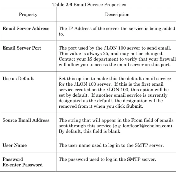
Figure 2.9 Email Service Properties
Configure the properties on the Web page, and then click Submit to save the changes. Click Reset to leave all fields unchanged.
Table 2.6 describes the email service properties.
Table 2.6 Email Service Properties
Property Description Email Server Address The IP Address of the server the service is being added
to.
Email Server Port The port used by the i.LON 100 server to send email. This value is always 25, and may not be changed. Contact your IS department to verify that your firewall will allow you to access the email server on this port. Use as Default Set this option to make this the default email service
for the i.LON 100 server. If this is the first email service created on the i.LON 100, this option will be set by default. If another email service is currently designated as the default, the designation will be removed from it when you click Submit.
Source Email Address The string that will appear in the From field of emails sent through this service (e.g. [email protected]). By default, this field is blank.
User Name The user name used to log in to the SMTP server. Password
i.LON 100 e3 User’s Guide 25
Configuring the Web Binder Destination Service
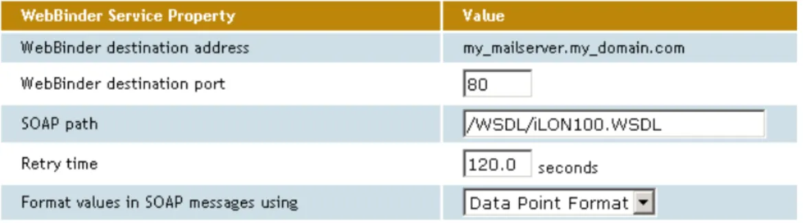
Web Binding is a process by which you can connect data points on your i.LON 100 server directly to data points on another i.LON 100 server, or to a third party Web server such as Apache or IIS, and keep the values of those data points synchronized. If you selected the Web Binder Destination service, you can use the associated server as a Web Binder destination. The right-hand side of the Network - LAN/WAN web page will appear as shown in the Figure 2.10.
Figure 2.10 Web Binder Service Properties
Configure the properties on the Web page, and then click Submit to save the changes. Click Reset to leave all fields unchanged.
Table 2.7 describes the properties you need to set to configure the Web Binder service. For more information on the Web Binder service, including instructions on how to set up a Web Binder connection, see Chapter 10, Web Binding.
Table 2.7 Web Binder Service Properties
Property Description Web Binder Destination
Address The IP Address or hostname of the server the service is being added to. Web Binder Destination
Port The port the server will use to receive Web Binder messages. By default, this value is 80, but it may be changed to any valid port number. Contact your IS department to assure your firewall is configured to allow you to access the server on this port.
SOAP Path The path to which SOAP messages should be directed on the server. This is typically the location of the WSDL or ASMX file on the destination server where it receives HTTP
requests used in a SOAP message transaction. By default, this is /WSDL/iLON100.WSDL (the default
Property Description Retry Time The i.LON 100 server will retry failed Web Binder
connection messages every 45 seconds. Use this property to set the amount of time after which the i.LON 100 server will stop retrying to send the message.
Format Values in SOAP
Messages Using This determines how the data in the SOAP messages sent to this Web Binder destination will be formatted. Select Raw Hex to format the data in raw hexadecimal format. Select Data Point Formats to format the data using the format specification assigned to the data point being updated by the SOAP message.
Configuring the LNS Uplink Service
If you selected the LNS Uplink service, you can establish an uplink LNS
connection with associated server (note that the LNS server must be running at the specified location). The right-hand side of the Network - LAN/WAN web page will appear as shown in Figure 2.11.
Figure 2.11 LNS Uplink Service Properties
Configure the properties on the Web page, and then click Submit to save the changes. Click Reset to leave all fields unchanged.
Table 2.8 describes the properties you need to set to configure the LNS uplink service properties.
Table 2.8 LNS Uplink Service Properties
Property Description LNS Uplink Address The IP Address or hostname of the server the
service is being added to.
LNS Uplink Port The port used by the i.LON 100 server to send LNS messages. By default, this value is 1628, but it may be changed to any valid port number. Contact your IS department to assure that your firewall will allow you to access the LNS server on this port.
i.LON 100 e3 User’s Guide 27
Property Description Use As Default Set this option to make this the default LNS
uplink service for the i.LON 100 server. If this is the first LNS uplink service created on the i.LON 100 server, this option will be enabled by default. If another LNS uplink service is currently
designated as the default, the designation will be removed from it when you click Submit.
Configuring the Time Service
If you selected the Time service, you can use the associated server as a time server (note that a time server must be running at the specified location). The right-hand side of the Network - LAN/WAN web page will appear as shown in Figure 2.12.
Figure 2.12 Time Service Properties
Configure the properties on the Web page, and then click Submit to save the changes. Click Reset to leave all fields unchanged.
Table 2.9 describes the time service properties you need to set to configure. Table 2.9 Time Service Properties
Property Description Time Server Address The IP Address or hostname of the server the
service is being added to.
Time Server Port The port used by the i.LON 100 server to receive time data. This value is always 123 and cannot be changed. Contact your IS department to assure that your firewall is configured to allow you to access the time server on this port.
Property Description Use As Default Set this option to make this the default time
service for the i.LON 100 server. If this is the first time service created on the i.LON 100 server, this option will be enabled by default. If another time service is currently designated as the default, the designation will be removed from it when you click Submit.
Configuring the IP-852 Configuration Server Service
If you selected the IP-852 Configuration Server, you can use the associated server as the Configuration Server for the IP-852 network the i.LON 100 server is connected to. The right-hand side of the LAN/WAN web page will appear as shown in Figure 2.13.
Figure 2.13 IP-852 Configuration Service Properties
Configure the properties on the Web page, and then click Submit to save the changes. Click Reset to leave all fields unchanged.
Table 2.10 describes the IP-852 routing properties you need to set to configure. Consult the IP-852 Channel User’s Guide for further instructions to follow when setting up the Configuration Server.
Table 2.10 IP-852 Routing Properties
Property Description IP-852 Configuration
Server Address The IP Address or hostname of the Configuration Server.
IP-852 Configuration
Server Port The port the Configuration Server will use to receive messages from the i.LON 100 server. IP-852 Router Local Port The port the i.LON 100 sever will use to receive
messages from the Configuration Server. You must license the i.LON 100 server to operate as an IP-852 router before using it on an IP-852 network. For more information on this, see Chapter 12, Sending ANSI/CEA-709.1 Packets Over IP with the i.LON 100 Server.
i.LON 100 e3 User’s Guide 29
Verifying
i.
LON 100 Connections
The i.LON 100 Internet Server includes a Web page that you can use to verify communications between your i.LON 100 server and LNS Servers, SMTP Servers, ISPs, other i.LON 100 devices, and third party Web servers. To open this Web page, point your mouse cursor to Setup, and then select Verify from the dropdown menu. The Setup - Verify Web page opens.
Figure 2.14 Setup - Verify Web Page
This Web page lists the services that have been configured on the Network - LAN/WAN Web page, including tests for the IP-852 router configuration settings and the persistent GPRS settings. By default, the Web page is configured to test all of the services. You can clear a checkbox to prevent verification of a service. To begin testing, click Start Tests. Any problems establishing communications with any of the servers will be reported.
When initiating a remote test from this web page, the i.LON server will be forced to dial out to each Dial-up connection that contains one or more services. If the i.LON server needs to break communication with this PC during that
communication, do not attempt a refresh during the process.
Testing of dial-up connections while dialed in to the i.LON 100 server will fail, because the Web page will not be able to maintain communication with the i.LON 100 after the modem disconnects and dials to another location. At any time during a test, you can click Cancel to clear all ongoing tests.
Configuring Modem Settings
Some i.LON 100 server models are equipped with an internal modem. In
addition, you can connect an external GSM modem to the Serial port. If you plan to dial-out from the i.LON 100 server, you must also create one or more dial-up connections, as described in the Creating and Configuring a Dial-up Connection section on page 18. To support dial-in connections, you must set the Enable
Dial-in option on the Security Web page, as described Dial-in the i.LON 100 Server Security section on page 55.
If your i.LON 100 server is equipped with a modem or attached to an external modem, you can configure it by pointing your mouse cursor to Setup, and then selecting Modem from the drop-down menu. The Setup - Modem Web page opens.
Figure 2.15 Setup - Modem Web Page
Configure the properties on the Modem Web page, and then click Submit to save the changes you have made. Click Reset to set all fields on this Web page back to the values they had when the page was opened.
i.LON 100 e3 User’s Guide 31 Tables 2.11 and 2.12 describe the properties you can configure on the Setup - Modem Web page.
Table 2.11 Modem Properties
Property Description Modem Select the modem that the i.LON 100 server will use. Select
Internal Analog to use the internal modem. Select External GSM Nokia 30 to 31 Series, External GSM Siemens 35 to 45 Series, or External GSM Insys GPRS 4.0 to 4.1 Series to use an external modem connected via the serial port.
Note that many GSM service provider contracts do not include provisions for establishing data-only connections. Contact your GSM provider to assure that you have data-only connections activated for your GSM contract.
User Name For Incoming
Calls The user name for incoming calls. This user name must be provided by the caller when attempting to connect to the i.LON 100 server via modem. By default, the user name is
ilon.
Field Length: Up to 30 characters. Password For Incoming
Calls/Re-enter Password The password for incoming calls. This password must be provided by the caller when attempting to connect to the i.LON 100 server via modem. The password will appear as asterisks when entered. You must reenter the password to assure that you typed it correctly. By default, the password name is ilon.
Select the Advanced check box on the Modem Web page to set advanced modem properties. Table 2.12 describes these properties.
Table 2.12 Advanced Modem Properties
Property Description Local IP Address For
Incoming Calls Set the IP address that will be assigned to incoming calls by the i.LON 100 server. By default, this is 198.162.2.2.
PPP Authentication The PPP (Point-to-Point Protocol) authentication type to be used for outgoing calls. Select CHAP to use the Challenge Handshake Authentication Protocol, which is an
authentication scheme used by PPP servers to validate the identity of the originator of a connection, upon connection or any time later.
Select PAP to use the Point-to-Point Access Protocol, which should generally used if CHAP is not available, or if the user name and password that the user submitted to PAP must be sent to another program without encryption.
Modem Country/Region Select the country in which the i.LON 100 server is located. The i.LON 100 server must be rebooted for changes to this property to take effect. This option is only available if Modem is set to Internal Analog.
Tone
Pulse This option appears only if Modem is set to Internal Analog. Select Tone or Pulse to determine whether the i.LON 100 server Internet Server’s modem will dial using touch-tone or pulse dialing. By default, this is set to Tone.
Dialing Prefix This option appears only if Modem is set to Internal Analog. If the i.LON 100 server is connected to a phone system that requires a code to be dialed to reach an outside line, enter the code here. By default, these fields are blank.
Legal Characters: Digits only Field Length: 30 characters
Delay After Prefix This option appears only if Modem is set to Internal Analog. If the Dialing Prefix field contains a prefix, enter the delay, in seconds, between the prefix being dialed and the phone number being dialed. The i.LON 100 server must rebooted for changes to this property to take effect. By default, this value is 0.0.
Legal Characters: Floating point number greater than or equal to 0 and an increment of .1.
i.LON 100 e3 User’s Guide 33
Property Description Dial Tone Waiting Select the Dial Tone Waiting check box if you want the
modem to wait for a dial tone before dialing out. PIN Number Set the PIN Number that must be send to the external
modem to send or receive calls. This option only appears if you are using an external modem.
Field Length: Up to 30 characters.
Access Point Name (APN) Set the APN hostname required by most GPRS service providers. This can be a valid IP address or a valid hostname and domain suffix pair. This option only appears if you are using an external modem.
Field Length: Up to 64 characters.
Quality of Service (QoS) Set the QoS string required by most GPRS providers. This option only appears if you are using an external modem. Field Length: Up to 30 characters.
Configuring L
ON
W
ORKS
Settings
You need to configure the server’s LONWORKS settings if you plan to use the
i.LON 100 Internet Server as a Remote Network Interface or as an IP-852 router, or if you plan to use the NVE driver to create data points on external devices. To do so, click Network on the title bar and then select LONWORKS from the