ERDAS
Spatial Modeler Language
Reference Manual
ERDAS IMAGINE
™
V8.5
ERDAS
®, Inc.
Atlanta, Georgia
Copyright 2000 by ERDAS, Inc. All Rights Reserved. Printed in the United States of America.
ERDAS Proprietary - Delivered under license agreement.
Copying and disclosure prohibited without express written permission from ERDAS, Inc.
ERDAS, Inc.
2801 Buford Highway, NE, Suite 300 Atlanta, Georgia 30329-2137 USA Toll Free: 877/GO-ERDAS (463-7327) Phone: 404/248-9000 Fax: 404/248-9400 User Support: 404/248-9777 www.erdas.com Acknowledgments Warning
All information in this document, as well as the software to which it pertains, is proprietary material of ERDAS, Inc., and is subject to an ERDAS license and non-disclosure agreement. Neither the software nor the documentation may be reproduced in any manner without the prior written permission of ERDAS, Inc.
Specifications are subject to change without notice.
Trademarks
ERDAS and ERDAS IMAGINE are registered trademarks; CellArray, ERDAS Stereo Analyst, IMAGINE Developers’ Toolkit, IMAGINE OrthoBASE, IMAGINE OrthoMAX, IMAGINE Vector, and IMAGINE VirtualGIS are trademarks. Other brands and product names are the properties of their respective owners. IMAGINE OrthoBASE/ IMAGINE OrthoBASE Pro Version 8.5 1999-2001. .
Table of Contents
Table of Contents
Section I
Introduction to SML . . . 1
Introduction . . . 1 Conventions . . . 1 Words enclosed in < > . . . 1 Strings . . . 1 Numbers . . . 1 Statements . . . 2 Object Types . . . 2 Data Types . . . 2 Variables . . . 3 Windows . . . 3 Working Window . . . 3Setting Windows on Layers . . . 3
Bin Functions . . . 4
Purpose of Bin Functions . . . 4
Example of a Bin Function . . . 4
Types of Bin Functions . . . 4
Default Bin Function for Output Data File Types . . . 6
Modeler Language Statements . . . 7
General Syntax . . . 7
Statements . . . 7
Comments . . . 7
Case . . . 8
Declaration Statements . . . 9
Declaration Statement Format . . . 9
SCALAR Declarations . . . 10
TABLE Declarations . . . 10
Associating Table Variables With Descriptors and Color Tables . . . 11
Examples of Table Declarations . . . 12
Associating Table Variables With Vector Attributes . . . 13
MATRIX Declarations. . . 14 RASTER Declarations . . . 15 Using Files . . . 15 File Parameters . . . 17 Existence Parameters . . . 17 Access Parameters . . . 18
Data Type Parameters . . . 18
Default Data Types . . . 20
Layer Type Parameters . . . 20
Interpolation Parameters . . . 21
Window Specification . . . 21
Area of Interest Specification . . . 21
Statistics Parameters . . . 22
Table of Contents
Edge Extension Specification . . . 23
Examples of Raster Declarations . . . 23
Data Type Examples . . . 25
VECTOR Declarations . . . 25
Parameters . . . 26
Window Specification . . . 26
Area of Interest Specification . . . 26
Cellsize Specification . . . 27
Feature Type Specification . . . 27
Rendering Method Specification . . . 28
Expressions . . . 29 Constants . . . 29 Binary Constants . . . 29 Integer Constants . . . 29 Float Constant . . . 29 Complex Constants . . . 30 Color Constants . . . 30 String Constants . . . 31 Variable References . . . 31
Using Operators and Functions . . . 31
Table Subexpressions . . . 32
Matrix Subexpressions . . . 32
Raster Layer Stacks . . . 33
Assignment Statements . . . 35
Example Assignments . . . 35
Data Type Assignment Compatibility . . . 35
Object Type Assignment Compatibility . . . 35
ASCII Input-Output Statements . . . 37
SHOW Statement . . . 37 READ Statement . . . 37 WRITE Statement . . . 37 VIEW Statement . . . 38 Setting Windows . . . 39 SET WINDOW . . . 39 SET CELLSIZE . . . 40
Other SET Statements. . . 40
SET AOI . . . 40
SET DEFAULT <datatype> . . . 41
SET DEFAULT ORIGIN . . . 41
SET DEFAULT INTERPOLATION . . . 41
SET DEFAULT STATISTICS . . . 42
SET TILESIZE . . . 42
SET RANDOM SEED . . . 42
QUIT Statement . . . 43
Statement Blocks . . . 43
Flow Control . . . 45
Conditional Branching . . . 45
Table of Contents
Macro Definitions . . . 46
Running the Spatial Modeler . . . 47
Running from IMAGINE . . . 47
Model Maker . . . 47
Running from the Command Line . . . 47
Model Arguments . . . 48
Command Line Options . . . 49
Statistics Computation and Descriptor Column Output. . . 50
Errors . . . 51
Syntax Errors . . . 51
Processing Errors . . . 51
Common Causes of Errors . . . 51
Standard Rules for Combining Different Types . . . 53
Data Types . . . 53
COLOR Data Type . . . 54
Object Types . . . 54
SectionII
SML Function Syntax . . . 57
Function Types . . . 57 Point Functions . . . 57 Neighborhood Functions . . . 57 Global Functions . . . 57 Zonal Functions . . . 58 Layer Functions . . . 58 Combination Functions . . . 58Modeler Function Categories . . . 59
Analysis . . . 61
CLUMP (Clump - Contiguity Analysis) . . . 62
CONVOLVE (Convolution) . . . 64
CORRELATION (Correlation Matrix From Covariance Matrix) . . . 65
CORRELATION (Correlation Matrix From Raster). . . . 66
COVARIANCE (Covariance Matrix) . . . 68
DELROWS (Delete Rows from Sieved Descriptor Column) . . . 70
DIRECT LOOKUP (Map Integer Values Through Lookup Table) . . . 72
EIGENMATRIX (Compute Matrix of Eigenvectors) . . . 73
EIGENVALUES (Compute Table of Eigenvalues) . . . 74
HISTMATCH (Histogram Matching) . . . 75
HISTOEQ (Histogram Equalization). . . 76
HISTOGRAM (Histogram) . . . 78
LINEARCOMB (Linear Combination) . . . 80
LOOKUP (Map Input Values Through Lookup Table Using Bin Function). . . 81
PRINCIPAL COMPONENTS (Principal Components) . . . 82
RASTERMATCH (Raster Matching) . . . 84
SIEVETABLE (Get Sieve Lookup Table) . . . 86
STRETCH (Stretch) . . . 87
Arithmetic . . . 89
+ (Addition) . . . 90
Table of Contents
- (Negation) . . . 92 * (Multiplication) . . . 93 / (Division) . . . 94 MOD (Modulus) . . . 95 ! (Factorial). . . 96 Bitwise . . . 97& (Bitwise And) . . . 98
| (Bitwise Or) . . . 99
^ (Bitwise Exclusive Or) . . . 100
~ (Bitwise Not) . . . 101
Boolean . . . 103
AND (Logical And) . . . 104
OR (Logical Or) . . . 105
NOT (Logical NOT) . . . 106
Color . . . 107
COLOR (Create Color Scalar) . . . 108
HUE (Get Hue from RGB) . . . 109
IHSTOBLU (Get Blue from Intensity, Hue, and Saturation) . . . 111
IHSTOGRN (Get Green from Intensity, Hue, and Saturation) . . . 112
IHSTORED (Get Red from Intensity, Hue and Saturation) . . . 113
IHSTORGB (Get Red, Green and Blue from Intensity, Hue and Saturation). . . 114
INTENS (Get Intensity from RGB) . . . 115
RGBTOIHS (Get Intensity, Hue and Saturation from Red, Green and Blue). . . 116
SATUR (Get Saturation from RGB) . . . 117
STACK (Convert FLOAT TABLE to COLOR SCALAR). . . 118
UNSTACK (Convert COLOR SCALAR to FLOAT TABLE) . . . 119
Conditional . . . 121
CONDITIONAL (Conditional) . . . 122
EITHER...IF...OR....OTHERWISE (Select on Binary Test) . . . 123
INDEX (Index - Find Matching Item on List) . . . 124
PICK (Pick - Get nth Item on List) . . . 125
Data Generation . . . 127
MAPX (Create Raster Containing X Map Coordinates) . . . 128
MAPY (Create Raster Containing Y Map Coordinates) . . . 129
MATRIX (Create Matrix from List of Scalars). . . 130
MATRIX (Read Matrix from Kernel Library) . . . 131
MATRIX SERIES (Create Matrix Containing 2-D Series) . . . 132
PIXELX (Create Raster Containing Column Number) . . . 133
PIXELY (Create Raster Containing Row Number) . . . 134
RANDOM (Generate Random Values) . . . 135
STACKLAYERS (Stack Raster Layers) . . . 136
TABLE (Create Table from List of Scalars) . . . 137
TABLE SERIES (Create Table Containing Series) . . . 138
Descriptor . . . 139
. (Map Raster Through Descriptor Column). . . 140
:: (Read Descriptor Column or Color Table) . . . 141
Distance . . . 143
CIRC (Test if Inside Unit Circle). . . 144
Table of Contents
RECT (Rectangle) . . . 146
SEARCH (Search - Proximity Analysis) . . . 147
TRI (Triangle) . . . 148
Exponential . . . 149
EXP (Exponential) . . . 150
LOG (Natural Logarithm) . . . 151
LOG10 (Common Logarithm). . . 152
POWER (Raise to Power) . . . 153
SQRT (Square Root) . . . 154
Focal (Scan) . . . 155
BOUNDARY (Boundary) . . . 156
FOCAL DENSITY (Focal Density) . . . 158
FOCAL DIVERSITY (Focal Diversity) . . . 160
FOCAL MAJORITY (Focal Majority) . . . 162
FOCAL MAX (Focal Maximum) . . . 164
FOCAL MEAN (Focal Mean) . . . 166
FOCAL MEDIAN (Focal Median) . . . 168
FOCAL MIN (Focal Minimum) . . . 170
FOCAL MINORITY (Focal Minority) . . . 172
FOCAL RANK (Focal Rank). . . 174
FOCAL SD (Focal Standard Deviation) . . . 176
FOCAL STANDARD DEVIATION (Focal Standard Deviation) . . . 178
FOCAL SUM (Focal Sum) . . . 180
Global . . . 183
GLOBAL DIVERSITY (Global Diversity) . . . 184
GLOBAL MAJORITY (Global Majority) . . . 186
GLOBAL MAX (Global Maximum) . . . 188
GLOBAL MEAN (Global Mean) . . . 190
GLOBAL MEDIAN (Global Median) . . . 192
GLOBAL MIN (Global Minimum) . . . 194
GLOBAL MINORITY (Global Minority) . . . 196
GLOBAL SD (Global Standard Deviation) . . . 198
GLOBAL STANDARD DEVIATION (Global Standard Deviation) . . . 200
GLOBAL SUM (Global Sum) . . . 202
Matrix . . . 205
MATDIV (Matrix Division) . . . 206
MATINV (Matrix Inverse) . . . 207
MATMUL (Matrix Multiplication) . . . 208
MATRIXTOTABLE (Convert Matrix to Table). . . 209
MATTRANS (Matrix Transpose) . . . 210
TABLETOMATRIX (Convert Table to Matrix). . . 211
Other . . . 213
ABS (Absolute Value). . . 214
ANGLE (Angle). . . 215
BINARY (Convert to Binary). . . 216
CEIL (Ceiling) . . . 217
COMPLEX (Convert to Complex). . . 218
CONJ (Complex Conjugate). . . 219
DELTA (Delta) . . . 220
Table of Contents
FLOAT (Convert to Float) . . . 222
FLOOR (Floor) . . . 223
GAMMA (Gamma) . . . 224
IMAG (Imaginary Part) . . . 225
INTEGER (Convert to Integer). . . 226
INV (Multiplicative Inverse) . . . 227
ODD (Test if Odd) . . . 228
REAL (Real Part) . . . 229
ROUND (Round) . . . 230
SIGN (Sign) . . . 231
SINC (Sinc) . . . 232
STEP (Step). . . 233
TRUNC (Truncate). . . 234
WHOLE (Test if Whole Number) . . . 235
Relational . . . 237
EQ (Equality) . . . 238
GE (Greater Than or Equal). . . 239
GT (Greater Than) . . . 240
LE (Less Than or Equal) . . . 241
LT (Less Than). . . 242
NE (Inequality) . . . 243
=~ (Case Insensitive String Equality). . . 244
!~ (Case Insensitive String Inequality) . . . 245
ISALLTRUE (Test for All Non-zero) . . . 246
ISNONZERO (Test for Non-zero) . . . 247
Size . . . 249
CELLAREA (Area of Grid Cells) . . . 250
CELLUNITS (Cell Size Units) . . . 251
CELLX (X Cell Size). . . 252
CELLY (Y Cell Size). . . 253
LAYERHEIGHT (Height of Raster Layer) . . . 254
LAYERWIDTH (Width of Raster Layer) . . . 255
NUMCOLS (Number of Columns) . . . 256
NUMLAYERS (Number of Layers). . . 257
NUMROWS (Number of Rows) . . . 258
Stack. . . 259
STACK DIVERSITY (Stack Diversity) . . . 260
STACK MAJORITY (Stack Majority) . . . 261
STACK MAX (Stack Maximum) . . . 262
STACK MEAN (Stack Mean) . . . 263
STACK MEDIAN (Stack Median). . . 264
STACK MIN (Stack Minimum) . . . 265
STACK MINORITY (Stack Minority) . . . 266
STACK SD (Stack Standard Deviation) . . . 267
STACK STANDARD DEVIATION . . . 268
STACK SUM (Stack Sum) . . . 269
Statistical (Local) . . . 271
DENSITY (Local Density) . . . 272
DIVERSITY (Local Diversity) . . . 273
Table of Contents
MAX (Local Maximum) . . . 275
MEAN (Local Mean) . . . 276
MEDIAN (Local Median). . . 277
MIN (Local Minimum) . . . 278
MINORITY (Local Minority) . . . 279
RANK (Local Rank) . . . 280
SD (Local Standard Deviation). . . 281
STANDARD DEVIATION (Local Standard Deviation) . . . 282
SUM (Local Sum) . . . 283
String . . . 285
CAT (Concatenate Strings) . . . 286
LENGTH (Length of String) . . . 287
LOWERCASE (Lowercase Conversion) . . . 288
MATCHES (String Wildcard Match) . . . 289
UPPERCASE (Uppercase Conversion) . . . 290
Surface . . . 291
ASPECT (Aspect). . . 292
DEGREE SLOPE (Degree Slope) . . . 293
PERCENT SLOPE (Percent Slope) . . . 294
RELIEF (Shaded Relief). . . 295
Trigonometric . . . 297
ACOS (Arccosine) . . . 298
ACOSH (Hyperbolic Arccosine) . . . 299
ASIN (Arcsine) . . . 300
ASINH (Hyperbolic Arcsine) . . . 301
ATAN (Arctangent) . . . 302
COS (Cosine) . . . 303
COSH (Hyperbolic Cosine) . . . 304
SIN (Sine). . . 305
SINH (Hyperbolic Sine) . . . 306
TAN (Tangent) . . . 307
TANH (Hyperbolic Tangent) . . . 308
Zonal . . . 309
SUMMARY (Cross Tabulation) . . . 310
ZONAL DIVERSITY (Zonal Diversity) . . . 311
ZONAL MAJORITY (Zonal Majority) . . . 312
ZONAL MAJORITY COUNT (Zonal Majority Count) . . . 313
ZONAL MAJORITY FRACTION (Zonal Majority Fraction). . . 314
ZONAL MAX (Zonal Maximum from Summary) . . . 315
ZONAL MAX (Zonal Maximum from Two Rasters) . . . 316
ZONAL MEAN (Zonal Mean from Summary) . . . 317
ZONAL MEAN (Zonal Mean from Two Rasters) . . . 318
ZONAL MEDIAN (Zonal Median) . . . 319
ZONAL MIN (Zonal Minimum from Summary) . . . 320
ZONAL MIN (Zonal Minimum from Two Rasters) . . . 321
ZONAL RANGE (Zonal Range from Summary) . . . 322
ZONAL RANGE (Zonal Range from Two Rasters) . . . 323
ZONAL SD (Zonal Standard Deviation from Summary). . . 324
ZONAL SD (Zonal Standard Deviation from Two Rasters) . . . 326
Table of Contents
ZONAL STANDARD DEVIATION (from Two Rasters) . . . 330
Section III
Indexes . . . 333
Index of Symbols . . . 333 Index of Keywords . . . 334Section I
Introduction to SML
Introduction
TheSpatial Modeler Language is a script language that is designed for GIS modeling and image processing applications. The Spatial Modeler language allows you to define simple or complex processing operations outside ofModel Maker, the graphical user interface in the Spatial Modeler component. Models created with Model Maker can be edited with the Spatial Modeler Language. However, the models which are created or edited using the Spatial Modeler Language cannot be accessed from Model Maker.Operations that you can perform with the Spatial Modeler include:
• mathematical operations on raster layers (adding, subtracting, multiplying, ratioing, or other image algebra functions)
• convolution filtering
• neighborhood analyses (analyzing a pixel based on the values of neighboring pixels) • subsetting and mosaicking
• principal components analysis • proximity analysis
• contiguity analysis
• descriptor table manipulation
Conventions The following conventions are used in this On-Line Help document:
Words enclosed in < >
When you see words with < > around them, you need to substitute these words with the proper information. For example, when you see the following in this document:
SCALAR <name>;
you would substitute the actual name of the variable so that the actual statement syntax would be something like:
SCALAR scalefactor;
Strings
A string is a group of words or characters. You must use quotation marks to enclose a string. Numbers
A number can either be a floating-point number or an integer and can either be positive or negative (i.e. 2.5, -2.5, 2 or -2).
Introduction to SML
Statements A model consists primarily of one or morestatements. Each statement falls into one of the following categories:
• Declarations - define objects to be manipulated within the model • Assignments - assign a value to an object
• SHOW andVIEW statements - allow you to see and interpret results from the model • SET statements - define the scope of the model or establish default values used by the
Spatial Modeler
• Macro Definitions - define substitution text associated with a macro name. • QUIT statement - end execution of the model
The Spatial Modeler Language also includesflow control structures, so that you can use conditional branching and looping in your models andstatement block structures, which cause a set of statements to be executed as a group.
Object Types The basic entities which can be manipulated within the Spatial Modeler Language are called objects. Each object falls into one of the following categories:
• SCALAR - a single numeric value, color, or character string.
• TABLE - a series of numeric values, colors, or character strings. A table has one column and a fixed number of rows. Tables are typically used to store columns from a descriptor table or a list of values which pertains to the individual layers of a multi-layer image file. For example, a table with 4 rows could be used to store the maximum value from each layer of a 4-layer image file.
• MATRIX - a set of numbers arranged in a two-dimensional array. A matrix has a fixed number of rows and columns. Matrices may be used to store convolution kernels or the neighborhood definition used in neighborhood functions. They can also be used to store covariance matrices, eigenvector matrices, or matrices of linear combination coefficients. • RASTER - a single layer or multi-layer array of pixel data. Rasters are typically used to
contain and manipulate data from image files.
• VECTOR - vector data in either a vector coverage or annotation layer can be read directly into the modeler, converted from vector to raster, then processed similarly to raster data. The modeler cannot write to coverages or annotation layers.
The size of a RASTER is defined by a window, which will be discussed inWindows. Data Types Each object within the Spatial Modeler stores data in one of the following data types:
• BINARY - either 0 (FALSE) or 1 (TRUE)
• INTEGER - integer values from -2,147,483,648 to 2,147,483,647 (signed 32-bit integer) • FLOAT - floating point data (double precision)
• COMPLEX - complex data (double precision)
• COLOR - three floating point numbers in the range 0.0 to 1.0 representing intensity of red, green, and blue
Introduction
Variables Variables are objects in the Spatial Modeler which have been associated with a name using a
Declaration statement. The declaration statement defines the data type and object type of the variable. The declaration may also associate a raster variable with certain layers of an image file or a table variable with a descriptor table.Assignment statements are used to set or change the value of a variable.
Windows Awindow is used to define the size and resolution used for a raster object. A window is a rectangle defined by an upper left (x,y) coordinate pair and a lower right (x,y) coordinate pair. These coordinates may be in either map units for georeferenced data or pixel units for non-georeferenced data.
If the coordinates are in map units, the window also contains an x and y cell size which defines the resolution of each pixel. If the coordinates are in pixel units, the cell size is assumed to be 1 pixel.
Working Window
A window called theWorking Window defines the size and resolution for all raster objects in the model. Each raster object, regardless of the size or resolution of the file with which it may be associated, is treated as having the size and resolution defined by the Working Window. When the file is read by the Spatial Modeler, the input data will be resampled, truncated, or padded with background values (normally 0) as needed so that the raster object matches the Working Window.
By default, the Working Window will be the union of the extents of all input layers in the model. The default cell size of the Working Window will be the minimum of the input cell sizes from all input layers.
The Working Window can be changed using theSET WINDOW andSET CELLSIZE statements. Setting Windows on Layers
When you declare a variable which is associated with an existing file, you have the option of setting a window for the variable. If the file is georeferenced, you may set the window in either map or pixel coordinates. If a pixel coordinate window is specified for a georeferenced file, the pixel coordinates are converted to map coordinates, and the resulting map coordinate window is used. If the file is not georeferenced, you may set the window in pixel coordinates only. If the Spatial Modeler tries to read data outside the window you have set, the background value will be read. If you do not set a window when declaring a variable, the effective window for each layer of the variable will be the extent of the corresponding layer in the image file.
Introduction to SML
Bin Functions
Purpose of Bin FunctionsAt the completion of a model, the Spatial Modeler will compute statistics and a histogram for each output raster layer. The histogram will be stored in a descriptor table for the output layer. The model may also output other descriptor columns to a descriptor table. SeeAssociating Table Variables With Descriptors and Color Tables.
Bins are used to group ranges of data values together for better manageability.Histograms and other descriptor columns for 1, 2, 4 and 8-bit data are easy to handle, since they contain a maximum of 256 rows. However, to have a row in a descriptor table for every possible data value in floating point, complex, and 32-bit data would yield an enormous amount of information.
Example of a Bin Function
Suppose we have a floating point data layer with values ranging from 0.0 to 1.0. We could set up a descriptor table with 100 rows with each row or bin corresponding to a data range of .01 in the layer.
The bins would look like the following:
Then, for example, row 23 of the histogram table would contain the number of pixels in the layer whose value fell between .023 and .024.
Types of Bin Functions Thebin function establishes the relationship between data values and rows in the descriptor table. There are four types of bin functions used in IMAGINE image layers:
Bin Number Data Range
0 X < 0.01 1 0.01 <= X < 0.02 2 0.02 <= X < 0.03 . . . 98 0.98 <= X < 0.99 99 0.99 <= X
Bin Functions
• DIRECT - one bin per integer value. Used by default for 1, 2, 4, and 8-bit integer data, but may be used for other data types as well. The direct bin function may include an offset for negative data, or data in which the minimum value is greater than zero. For example, a direct bin with 900 bins and an offset of -601 and would look like the following:
• LINEAR - establishes a linear mapping between data values and bin numbers, as in our first example, mapping the data range 0.0 to 1.0 to bin numbers 0 to 99.
The bin number is computed by:
where:
Bin Number Data Range
0 X <= -600.5 1 -600.5 < X <= -599.5 . . . 599 -2.5 < X <= -1.5 600 -1.5 < X <= -0.5 601 -0.5 < X < 0.5 602 0.5 <= X < 1.5 603 1.5 <= X < 2.5 . . . 898 296.5 <= X < 297.5 899 297.5 <= X
bin = numbins * (x - min) / (max - min) if (bin < 0) bin = 0
if (bin >= numbins) bin = numbins - 1
bin = resulting bin number
numbins = number of bins
x = data value
min = lower limit (usually minimum data value)
Introduction to SML
• LOG - establishes a logarithmic mapping between data values and bin numbers. The bin number is computed by:
• EXPLICIT - explicitly defines mapping between each bin number and data range.
Explicit bin functions are not accessible from the current version of the Spatial Modeler Language. They are only accessible through the C Programmers’ Toolkit.
Default Bin Function for Output Data File Types
• 1, 2, 4, and 8-bit integer layers:
Direct binning. Number of bins equals 2, 4, 16, and 256 respectively. • 16 and 32-bit integer layers:
If the difference between the maximum and minimum data values is less than 256, uses direct binning with an offset of the minimum data value; number of bins is: maximum -minimum + 1
If the difference is greater or equal to 256, linear binning from min to max with 256 bins is used by default.
• Floating point layers:
Linear binning from min to max, 256 bins. • Complex layers:
Linear binning from minimum magnitude to maximum magnitude, 256 bins. The complex values are converted to magnitude before computing bin number.
The declaration statement has options to override the default binning by setting the desired bin function type and number of bins for the output layer. See the sectionBin Function Specification
under Raster Declarations.
bin = numbins * (ln (1.0 + ((x - min)/(max - min)))/ ln (2.0)) if (bin < 0) bin = 0
General Syntax
Modeler Language
Statements
The Spatial Modeler Language includes several basic statements that you will use together to create models. These statements include:
• Declaration statements • Assignment statements • Visual output statements • SET statements
• Macro Definitions
• QUIT statement
Expressions are used in building statements.
General Syntax
A model may contain an almost unlimited number of lines of text.The indentation of the lines that are used in the example models here are used for clarity only— they are not necessary. However, if used, they will make your models more readable.
Statements Each statement in a model makes one definition or calculation. A statement may occupy more than one line. A semicolon must mark the end of each statement. The following statement is legal: YYYYYYYYYYYY = max ( AAAAAAAAAAAA, BBBBBBBBBBBB, CCCCCCCCCCCC, DDDDDDDDDDDD, EEEEEEEEEEEE, FFFFFFFFFFFF ) + 127;
Most syntax errors are caused when the semicolon is left off the end of a line. The line that is missing the semicolon is the line preceding the one in which the error is detected. For example, if a semicolon is missing on line 7, the error will appear on line 8.
Comments Any line that begins with a# character is considered a comment line, and will be ignored by the Modeler. An exception is theMacro Definition statement, which begins with #define. Comments can also be on lines with valid statements. Any text after a # is a comment (unless # is followed bydefine). Comment lines can be embedded anywhere within the model.
A comment does not need to end with a semicolon. However, if a comment is on the same line as a statement, the statement must end with a semicolon, and the# character must follow the semicolon.
The following lines contain comments. The text after the# is ignored by the Modeler.
#
# this is a comment
# # # # # # # # # # # # # # # # # # # # # # # # # # # this model worked on Tuesday
# RASTER abc file "xyz.img";
RASTER abc file "real.img"; # this is what I meant to do
Blank lines are also ignored by the Modeler.
You may also specify comments using the character sequences/* and*/. Any text which is between/*and*/ is ignored by the modeler. Comments delimited by /* and*/ may span multiple lines. For example:
/* This is an example of
a comment which spans several lines in a model */
Case The case of characters (e.g., UPPER CASE vs. lower case) is not recognized by the Modeler. Therefore, any text within a statement can be upper case or lower case, and the case does not need to be consistent within the model.
In the examples in this documentation, upper case is used for keywords, and lower case is used for variable names and other user-defined text. This is used for clarity and is not essential.
Declaration Statements
Declaration
Statements
Adeclaration statement establishes a variable in the model. It defines: • the name and size of the variable,
• its data type and • object type.
There are five types of declarations statements used in the Modeler:
SCALAR TABLE MATRIX RASTER VECTOR Declaration Statement Format
The basic format of the declaration statement is:
<datatype> <objecttype> <name> <sizedef> <other parameters>; where:
<datatype> Data type, either BINARY, INTEGER, FLOAT, COMPLEX, COLOR, or STRING. If the data type is omitted, the data type defaults to INTEGER.
<objecttype> Object type, either SCALAR, TABLE, MATRIX, RASTER, or VECTOR. If the object type is omitted, the object type defaults to SCALAR.
<name> The name you specify for the variable. The name must start with a letter and consist entirely of letters, numbers, and the underscore character (_). You cannot use any of thekeywords defined in the Spatial Modeler Language as variable names.
<sizedef> Sets the number of rows in a table, the number of rows and columns of a matrix, or the number of layers in a raster variable. The<sizedef> may also include a origin specifier, which specifies what index is to be used to identify the first row, column, or layer. The origin is usually either 0 or 1.
The<sizedef> component is not used for scalars or vectors, and may be omitted in the declaration of other types. If the variable is associated with existing file data, the size will be derived from the file. Otherwise, the size will be set on the first assignment to this variable.
<other parameters> May be used to associate a raster variable with an image file, or a table with a descriptor column, or set various parameters used when creating a new image file.
The<other parameters> used in associating rasters and tables with files are discussed in the following pages of this document.
SCALAR
Declarations
SCALAR variables may be declared with one of the following statements:
<datatype> SCALAR <name>;
or
SCALAR <name>;
or
<datatype> name;
If<datatype> is omitted, the data type defaults toINTEGER. If a variable is declared without an object type, then it defaults toSCALAR.
TABLE Declarations
The basic format of aTABLE declaration is the following:<datatype> TABLE <name> <sizedef>;
<datatype> and/or<sizedef> may be omitted. If<datatype> is omitted, data type defaults to INTEGER.
<sizedef> is one of the following:
[<size>]
[<origin>:<size>] [<origin>:]
<origin> is an integer constant specifying the index for the first row of the table. For example, if a table is declared as:
TABLE bob [0:7];
thenbob [0] is the first row of the table andbob [6] is the last row.
If<origin> is omitted, the origin will be the default table origin. The pre-set default table origin is zero. The default table origin may be reset using theSET DEFAULT ORIGIN TABLE statement, or may be set using thePreference Editor.
TABLE Declarations
<size> is a numeric scalar expression specifying the number of rows in the table variable. If <size> is non-integer, it will be converted to integer. If<size> is omitted, the number of rows will be set either by the descriptor table size or by the first assignment to the variable. If the table is associated with a descriptor table as described in the next section, the size of the descriptor table may determine the size of the declared table.
Associating Table Variables With Descriptors and Color Tables
TABLE variables may be associated in the declaration statement with a descriptor table column from an image file. The descriptor table column may already exist or be created by the model. • If the descriptor table column already exists, the column is read into the table variable
from the file. At the end of model execution, the table will be written back to the file with any new values that may have been assigned to the table by the model.
• If the descriptor table column does not already exist, the column will be created at the
end of model execution and values written into the file.
SeeStatistics Computation and Descriptor Column Output for more information on writing descriptor table columns.
The format for declaring a table associated with a descriptor column or color scheme is:
<datatype> TABLE <name> <sizedef> DESCRIPTOR <raster-exp> :: <descriptorname>;
or
COLOR TABLE <name> <sizedef> COLORTABLE <raster-exp>;
<datatype> and <sizedef> are described in the previous section,Basic Table Declarations. <raster-exp> is a raster expression which must represent a single layer raster object associated with a layer of an image file. The layer may already exist, or it may be a layer which will be created by this model. The<raster-exp> must be a reference to a raster variable, or a single layer of a raster variable, i.e.,<raster-exp> is either:
<raster-variable>
or
<raster-variable> (<layer-number>)
The<layer-number>, if present, must be an integer constant.
<descriptorname> is a string constant which specifies the name of the descriptor column to be associated with this variable. This may be an existing descriptor column, or the name of a new column to be created by the Modeler. If the descriptor column exists, the data type of the column must match the data type specified by the declaration. If the column does not exist, it will be created using the data type of this table variable.
The current version of the Modeler always defaults toINTEGER type, regardless of the data type of the associated descriptor table, and the type of the variable must match the type of the descriptor column.
If eitherDESCRIPTOR orCOLORTABLE is present in the declaration, and the descriptor table exists for the layer associated with the<raster-exp>, the number of rows will be set to the number of rows in the descriptor table for that layer. Otherwise, the number of rows for the table will be deferred until the first assignment statement assigning a value to the variable name. At that point, the number of rows in the expression being assigned to this variable determines the size.
TheCOLORTABLE keyword may be used only with a table ofCOLOR data type. The values found in the “Red,” “Green,” and “Blue” descriptor columns will be read into this table, or if these columns do not exist, the Modeler will create them.
Only one table variable may be associated with each descriptor column for a single layer. If you try to associate more than one table variable with the same descriptor column of the same layer, an error occurs. Also, since theCOLORTABLE keyword associates a table variable with the “Red,” “Green,” and “Blue” columns of a descriptor table, you may not associate another table variable with any of these three descriptor columns for the same layer.
Examples of Table Declarations
Please read the following sections before continuing with these examples:
• RASTER Declarations
• Variable References
• Raster Layer Stacks
• Bin Function Specification
Examples
TABLE tom;This declares an INTEGER TABLE namedtom of undefined size. The number of rows intom will be defined when an assignment is made totom.
RASTER in FILE OLD INPUT "infile.img";
STRING TABLE clnames DESCRIPTOR in :: "Class_Names";
This declares the table clnames and associates it with theClass_Names column of the descriptor table for the single layer in the existing fileinfile.img. The number of rows in clnames will be the number of bins in the descriptor table. The fileinfile.img must contain exactly one layer, or the Modeler will report an error.
RASTER in FILE OLD INPUT "mobbay.img";
FLOAT TABLE hist DESCRIPTOR in (3) :: "Histogram";
This time, the tablehist is associated with the histogram for layer 3 ofmobbay.img.
The current version of the Modeler always defaults toINTEGER type, regardless of the data type of the associated file data.
RASTER out FILE NEW OUTPUT "newfile.img";
TABLE Declarations
In this example,newfile.img is a new file, so the descriptor table has not been created yet. Thus the size ofclnames is undefined after the declaration, and will be defined by the first
assignment toclnames. The descriptor table fornewfile.img is not created until the statistics are computed at the end of model execution.
After the descriptor table is created, theClass_Names column is added, and the data in clnames is written to the column. If there are more rows inclnames than bins in the descriptor table, only the rows up to the number of bins are written out. If there are more bins in the descriptor table than rows inclnames, the remaining rows in the descriptor column will be initialized to"".
Also, note that the number of layers in theRASTER variableout was left undefined in its declaration. The declaration ofclnames assumes that out has only one layer, and in fact actually defines the number of layers inout to be one.
FLOAT TABLE hist DESCRIPTOR out (3) :: "Histogram";
This time, however, the number of layers inout is undefined whenout (3) is referenced in the declaration ofhist. This causes an error to be reported.
RASTER in FILE NEW INPUT "infile.img"; COLOR TABLE clrtab COLORTABLE in;
This declares the color table clrtab to be associated with the Red, Green, and Blue columns of the descriptor table for the single layer in the existing fileinfile.img.
Associating Table Variables With Vector Attributes
TABLE variables may also be associated in the declaration statement with an attribute of a vector coverage or an annotation layer. This is very similar to associating a table with a descriptor column from a raster image file. For vector coverages, the attribute may already exist may or be created by the model:
• If the attribute already exists, the attribute data is read into the table variable from the
file. At the end of model execution, the table will be written back to the attribute file with any new values that may have been assigned to the table by the model.
• If the attribute does not already exist, the attribute will be created at the end of model
execution and values written into the file.
For annotation layers, only the Name and Description can be treated as attributes. Either of these may be read from and/or written into. No new attributes for annotation can be created. The format for declaring a table associated with a attribute is:
<datatype> TABLE <name> <sizedef> ATTRIBUTE <vector-variable> :: <attributename>;
<datatype> and <sizedef> are described in the sectionBasic Table Declarations. The default data type isINTEGER, regardless of the type of attribute.
<attributename> is a string constant which specifies the name of the attribute to be associated with this variable. For vector coverages, this may be an existing attribute, or the name of a new attribute to be created by the Modeler. For annotation layers, <attributename> must be either “Name”or“Description”;
IfATTRIBUTE is present in the declaration, and the attribute table exists for the coverage or layer associated with the<vector-exp>, the number of rows will be set to the number of rows in the attribute table. Otherwise, the number of rows for the table will be deferred until the first assignment statement assigning a value to the variable name. At that point, the number of rows in the expression being assigned to this variable determines the size.
Only one table variable may be associated with each attribute for a single coverage or layer. If you try to associate more than one table variable with the same attribute, an error occurs.
MATRIX
Declarations
The basic form of a matrix declaration is:
<datatype> MATRIX <name> <sizedef>;
<datatype> and/or<sizedef> may be omitted. If<datatype> is omitted, data type defaults to INTEGER.
Matrix objects may not be declared asCOLOR orSTRING data types.
<sizedef> is one of the following:
[<rows>, <columns>]
[<roworigin>:<rows>, <columnorigin>:<columns>] [<roworigin>:, <columnorigin>:]
<roworigin> and<columnorigin> are integer constants specifying the index for the first row and first column of the table. For example, if a matrix is declared as:
MATRIX biff [1:3, 0:4];
then the elements of the matrix would be arranged as:
If<roworigin> and<columnorigin> are omitted, the origin for both rows and columns will be the default matrix origin. The pre-set default table origin is zero. The default matrix origin may be reset using theSET DEFAULT ORIGIN MATRIX statement or may be set using thePreference Editor.
<roworigin> and<columnorigin> must be constants.
biff [1,0] biff [1,1] biff [1,2] biff [1,3]
biff [2,0] biff [2,1] biff [2,2] biff [2,3]
RASTER Declarations
<rows> and<columns> are numeric scalar expressions specifying the number of rows and columns in the matrix variable. If<rows> or<columns> is non-integer, it will be converted to integer. If<rows> and<columns> are omitted, the number of rows and columns will be deferred until the first assignment statement assigning a value to the variable name. At that point, the number of rows and columns in the expression being assigned to this variable determines the size of the matrix.
RASTER
Declarations
The most basic format of a raster declaration is:
<datatype> RASTER <name> <sizedef>;
<datatype> and/or<sizedef> are optional. If<datatype> is omitted, data type defaults to INTEGER.
Raster objects may not be declared asCOLOR orSTRING data types.
<sizedef> is one of the following:
(<size>)
(<origin>:<size>) (<origin>:)
<origin> is an integer constant specifying the index for the first layer of the raster. For example, if a raster is declared as:
RASTER buffy (0:7);
thenbuffy (0) is the first layer of the raster andbuffy (6) is the last layer.
If<origin> is omitted, the origin will be the default raster origin. The pre-set default raster origin is one. The default table origin may be reset using theSET DEFAULT ORIGIN RASTER
statement or may be set using thePreference Editor.
<origin> must be a constant.
<size> is a numeric scalar expression specifying the number of layers in the raster variable. If <size> is non-integer, it will be converted to integer.
If<size>is omitted, the number of layers will be set by the first assignment to the variable. If the variable is associated with a raster file as described in the next section, the number of layers may be determined by the file.
Using Files RASTER variables may be associated with one or more layers of an image file within the declaration statement. The image file may be either an already existing file, a new file, or new layers within a file which the Modeler will create. There is a variety of keywords which you may use in the declaration to control the data type and various other parameters used when creating a new image file.
The format for declaring a raster variable associated with a file is:
<datatype> RASTER <name> <sizedef> FILE <file parameters> <layernames>;
<datatype> and<sizedef> are described in the previous section,Basic Raster Declarations. If<size>is omitted from <sizedef>, the number of layers will be set either by the number of layers specified in<layernames> or by the first assignment to the variable. If the
<layernames> component is present in the declaration, the number of layers for the raster may be determined by<layernames>. (See the examples at the end of this section.) Otherwise, the number of layers for the raster will be deferred until the first assignment statement assigning a value to the variable name. At that point, the number of layers in the expression being assigned to this variable determines the size.
<file parameters> may be any combination of parameters which specify how new layers should be created, criteria to test against existing layers, or how layers are to be read. File parameters include: OLD 64 BIT NEW 128 BIT DELETE_IF_EXISTING SINGLE INPUT DOUBLE OUTPUT THEMATIC INTEGER CATEGORICAL FLOAT ATHEMATIC COMPLEX CONTINUOUS
SIGNED NEAREST NEIGHBOR
UNSIGNED BILINEAR INTERPOLATION
1 BIT CUBIC CONVOLUTION
2 BIT WINDOW <windowspec>
4 BIT AOI <aoi-specification>
8 BIT BIN <binfunctionspec>
16 BIT EDGE REFLECT
32 BIT EDGE FILL
U1 UNSIGNED_1_BIT U2 UNSIGNED_2_BIT U4 UNSIGNED_4_BIT U8 UNSIGNED_8_BIT U16 UNSIGNED_16_BIT U32 UNSIGNED_32_BIT
RASTER Declarations
These parameters will be discussed in detail in the next section.
<layernames> is aSTRING constant which may contain either the name of a file or the name of a file followed by a list of layers from the file.
For example:
"/usr/data/mobbay.img"
would specify all layers in the file/usr/data/mobbay.img.
"/usr/data/mobbay.img(:Layer_4,:Layer_2,:Layer_1)"
specifies layers 4, 2, and 1 (in that order) from/usr/data/mobbay.img.
If explicit layer names are included in the<layernames> component, and a size is specified in the declarations (with <sizedef>), the number of layers must match the number specified in the size. If no layer names are specified, the total number of layers in the file must match the specified size (from <sizedef>). SeeExamples of Raster Declarations.
The Modeler will create temporary files for raster variables which are not associated with file layers. These temporary files will be deleted when the Modeler finishes executing the model.
These temporary files will be created in the “Temporary File Directory” specified in the
Preference Editor. The default is/tmp. If there is not enough space in/tmp for these files, you may wish to change the directory in which the Modeler creates temporary files by changing the preference.
File Parameters The following keywords and parameters may be inserted in any order between theFILE keyword and the<layernames> parameter. Generally, these keywords specify how new files or layers are to be created, or test conditions on existing files.
Existence Parameters
Existence parameters specify whether the layers named in<layernames> are expected to already exist at the time the model is run. They include:
OLD If OLD is present, the layers must already exist. Otherwise, an error is reported.
S8 SIGNED_8_BIT S16 SIGNED_16_BIT S32 SIGNED_32_BIT F32 FLOAT_SINGLE F64 FLOAT_DOUBLE C64 COMPLEX_SINGLE C128 COMPLEX_DOUBLE
NEW If NEW is present, the layers must not exist. If they do, an error is reported.
DELETE_IF_EXISTING IfDELETE_IF_EXISTING is present, and the layers already exist, they will be deleted immediately, and then recreated by the model.
If none of the existence parameters is present, the Modeler will open the layers if they exist, or create them if they do not exist.
Access Parameters
Access parameters specify access to the layers. They include:
INPUT Specifies that only read access is allowed to these layers. An error occurs if the model assigns a value to the associated variable.INPUT andNEW, orINPUT and DELETE_IF_EXISTING are incompatible.
OUTPUT Specifies read and write access to layers.
If no access parameter is specified, read and write access are permitted. Data Type Parameters
Thedata type parameters control which of the following data types is used for the layers specified in the declaration:
INTEGER Specifies one of the integer data types.
FLOAT Specifies one of the floating point data types.
COMPLEX Specifies one of the complex data types.
SIGNED Specifies a signed integer type.
UNSIGNED Specifies an unsigned integer type.
1 BIT 1-bit unsigned integer.
2 BIT 2-bit unsigned integer.
4 BIT 4-bit unsigned integer.
8 BIT 8-bit integer data (signed or unsigned).
16 BIT 16-bit integer data (signed or unsigned).
32 BIT 32-bit integer data (signed or unsigned) or single precision float.
64 BIT Specifies double precision float or single precision complex.
128 BIT Specifies double precision complex.
SINGLE Specifies single precision float or complex. FLOAT is used unless COMPLEX is specified or default is COMPLEX type.
DOUBLE Specifies double precision float or complex. FLOAT is used unless COMPLEX is specified or default is COMPLEX type.
RASTER Declarations
These data type parameters may be used together in any consistent combination. If any ambiguity about the data type persists after all data type parameters are specified, the default data types are used to resolve the ambiguity.
An error is reported if contradictory data type parameters are specified such asSIGNED FLOAT, 32 BIT COMPLEX, orSINGLE 16 BIT. An error will also be reported if redundant data type parameters are used together such as SIGNED S32.
Layers of image files in IMAGINE may be any of the following data types: U1
UNSIGNED_1_BIT
1-bit unsigned integer.
U2
UNSIGNED_2_BIT
2-bit unsigned integer.
U4
UNSIGNED_4_BIT
4-bit unsigned integer.
U8
UNSIGNED_8_BIT
8-bit unsigned integer.
U16
UNSIGNED_16_BIT
16-bit unsigned integer data.
U32
UNSIGNED_32_BIT
32-bit unsigned integer data.
S8
SIGNED_8_BIT
8-bit signed integer.
S16
SIGNED_16_BIT
16-bit signed integer data.
S32
SIGNED_32_BIT
32-bit signed integer data.
F64
FLOAT_DOUBLE
Specifies double precision float.
C64
COMPLEX_SINGLE
Specifies single precision complex.
C128
COMPLEX_DOUBLE
1-bit unsigned integer 2-bit unsigned integer 4-bit unsigned integer 8-bit unsigned integer 8-bit signed integer 16-bit unsigned integer 16-bit signed integer 32-bit unsigned integer 32-bit signed integer
32-bit (single precision) floating point 64-bit (double precision) floating point 64-bit (single precision) complex 128-bit (double precision) complex
If the specified layers already exist, these parameters are checked against the data type of the layers. If the layer data type is incompatible with the data type parameter, an error is reported. Default Data Types
If the specified layers do not exist, the data type of the variable defines the default data type for the new layers. The default data types are:
• BINARY variable: 1-bit unsigned integer • INTEGER variable: 8-bit unsigned integer
• FLOAT variable: 32-bit (single precision) floating point • COMPLEX variable: 64-bit (single precision) floating point
The default file data types for each modeler data type may be altered using theSET DEFAULT <datatype> statement or using thePreference Editor.
Layer Type Parameters Layer type parameters include:
THEMATIC CATEGORICAL ATHEMATIC CONTINUOUS
These parameters identify layers as either thematic (categorical), or athematic (continuous). Various programs in IMAGINE will treat thematic and athematic data differently.
• THEMATIC orCATEGORICAL - use thematic layers • ATHEMATIC orCONTINUOUS - use athematic layers
• THEMATIC andCATEGORICAL are incompatible with signed integer, floating point, and complex data, and these combinations will cause errors.
RASTER Declarations
Interpolation Parameters
Interpolation parameters determine the resampling method that will be used if an existing layer is not the same resolution as the Working Window.
NEAREST NEIGHBOR
BILINEAR INTERPOLATION CUBIC CONVOLUTION
The default interpolation isNEAREST NEIGHBOR. The default interpolation type may be changed using theSET DEFAULT INTERPOLATION statement or using thePreference Editor. New layers are always the same resolution as the Working Window, so interpolation is not used for new layers.
Window Specification
Thewindow specification sets a window on input layers. The format of the window specification is:
WINDOW <upper-left-x>, <upper-left-y> : <lower-right-x> <lower-right-y> MAP
or
WINDOW <upper-left-x>, <upper-left-y> : <lower-right-x> <lower-right-y> PIXEL
or
WINDOW <upper-left-x>, <upper-left-y> : <lower-right-x> <lower-right-y> FILE
The coordinates in the window specifications must be constants. Window specifications are ignored for output layers.
SeeSetting Windows for more information about layer windows. Area of Interest Specification
TheAOI specification sets an area of interest on input layers. The format of the AOI specification is:
AOI <filename>
<filename> is a string constant containing the name of a file that contains an area of interest. When the data file is read, areas outside the AOI will be set to the background value. The AOI specification is ignored if used in the declaration of an output file.
AOI NONE
See also theSET AOI statement for setting an area of interest on a model. Setting an AOI on an input file rather than on the model changes when the AOI is applied. For example, using the SEARCH function on a layer with an AOI would cause the function to search only from search class pixels inside the AOI. On the other hand, SEARCH applied to a file without an AOI, but inside a model with an AOI, would search from all search class pixels in the Working Window. The AOI is then applied to the output of the SEARCH function.
Statistics Parameters
Statistics parameters determine which values in the data file will be used or ignored for the computing of final statistics or inGlobal functions. Statistics parameters include:
USEALL <backgroundvalue>
Use all values present in the data file for computing statistics or global functions. <backgroundvalue> is optional and is not used if present.
IGNORE <backgroundvalue>
Ignore <backgroundvalue> when computing stats and global functions.<backgroundvalue> may be omitted, in which case zero values are ignored.
<backgroundvalue>, if present, must be a numeric constant.
The default for statistics isUSEALL. The default statistics computation may be changed using theSET DEFAULT STATISTICS statement, or using thePreference Editor.
Bin Function Specification
Thebin function specification controls the bin function used in new output layers. The bin function specification may indicate:
• the type of bin function,
• the type and number of bins or type, • number of bins, minimum and maximum.
If the bin function is completely specified, the descriptor table for each layer is created when the layer is created. If the bin function is only partially specified, the descriptor table is not created until the end of model execution, at which time statistics are computed, and the minimum and maximum used for the bin function are derived from the statistics. SeeBin Functions for an explanation of how bin functions are used.
The general format of a bin function specification is:
BIN <binfunctionspec>
However, the bin function specification may be any of the following formats:
BIN DIRECT DEFAULT
Use direct binning. The number of bins and offset are derived from statistics. The offset will be the minimum value (rounded to integer if necessary), the number of bins will be:
RASTER Declarations
maximum (rounded if necessary) - minimum + 1
Exception: ifTHEMATICis present, zero is used as the minimum, rather than the minimum file value. In this case the number of bins is:
maximum + 1
BIN DIRECT <numbins> BINS
Use direct binning, with an offset of zero, and<numbins> bins.
BIN DIRECT <numbins> BINS FROM <min> TO <max>
Use direct binning, offset<min>,<numbins> bins.<numbins> must equal<max> -<min> + 1.
BIN LINEAR <numbins> BINS
Use linear binning,<numbins> bins. Min and max are derived from statistics.
BIN LINEAR <numbins> BINS FROM <min> TO <max>
Use linear binning,<numbins> bins,<min> and<max> specified.
BIN LOG <numbins> BINS
Use logarithmic binning,<numbins> bins. Min and max are derived from statistics.
BIN LOG <numbins> BINS FROM <min> TO <max>
Use logarithmic binning,<numbins> bins,<min> and<max> specified.
<numbins>,<min> and<max> must be constants.
Edge Extension Specification
Theedge extension specification specifies how the edge of the data file is to be handled by neighborhood functions. Since the focus or kernel used by the neighborhood function typically extends beyond the edge of the data, the function must generate data values for pixels outside the edge. The specification is:
EDGE REFLECT
or
EGDE FILL
EGDE REFLECT specifies that data file values should be reflected around the edge of the data file to generate pixels outside the edge.EGDE FILL specifies that pixels outside the edge of the data are given the background value. The default isEDGE FILL.
Examples of Raster Declarations
This declares a raster variable namedjoe, which is not associated with a file. The number of layers injoe will be determined when an assignment is made tojoe.
RASTER bob (3);
This declares a raster variable namedbob with three layers.
RASTER henry FILE OLD "/usr/data/mobbay.img";
This declares a raster variable namedhenry, which is associated with all the layers of the existing file /usr/data/mobbay.img. If/usr/data/mobbay.img does not exist, the file parameterOLD causes an error to occur. The variablehenry has the same number of layers as the file/usr/data/mobbay.img.
RASTER bob (3) FILE OLD "/usr/data/mobbay.img";
This declares a raster variable namedbob, which is associated with all the layers of the existing file/usr/data/mobbay.img. If/usr/data/mobbay.img does not exist, the file parameterOLD causes an error to occur. The variablehenry is declared to have three layers. If
/usr/data/mobbay.img does not have exactly three layers, an error occurs.
RASTER muddy FILE OLD
"/usr/data/mobbay.img(:Layer_4,:Layer_2,:Layer_1)";
This declares a raster variable namedmuddy, which is associated with the listed layers of the existing file/usr/data/mobbay.img. The variablemuddy will have three layers, since three layers were listed in the<layernames> component.
RASTER skipper (3) FILE OLD
"/usr/data/mobbay.img(:Layer_1,:Layer_2)";
This will cause an error to occur, sinceskipper is declared to have three layers, but two layers were listed in the<layernames> component.
RASTER susie FILE NEW "/usr/data/newfile.img";
This will create a new image file named/usr/data/newfile.img. The number of layers in the file, and the number of layers in the variablesusie will be determined when an assignment is made to the variablesusie. If the file/usr/data/newfile.img already exists, the file parameterNEW will cause an error to occur.
RASTER jill FILE NEW
"/usr/data/newfile.img(:Layer_1,:Layer_2)";
This declares the variablejill with 2 layers. If:Layer_1or :Layer_2 is the name of an existing layer in the file/usr/data/newfile.img, an error occurs.
RASTER sam (3) FILE DELETE_IF_EXISTING "/usr/data/newfile.img";
This creates a new file named/usr/data/newfile.img with three layers. If there already existed a file called/usr/data/newfile.img, it is deleted first. Since no layer names are specified, the layers will be given the default names :Layer_1, :Layer_2,and :Layer_3.
VECTOR Declarations
Data Type Examples
Any data parameters in the declaration will modify the data type for the output layers based on the defaults. For example:
INTEGER RASTER a FILE NEW SIGNED "/usr/data/newfile.img";
Specifies that the layers of/usr/data/newfile.img will be 8-bit signed integer type.
You may specify any data type for the layers, regardless of the data type of the variable. For example, the following are valid declarations:
BINARY RASTER b FILE DOUBLE COMPLEX "/usr/data/complexfile.img";
COMPLEX RASTER c FILE 1 BIT "/usr/data/binaryfile.img";
The data types are converted automatically when reading from or writing to the file layers.
VECTOR
Declarations
Vector data in either a vector coverage or annotation layer can be read directly into the modeler, converted from vector to raster, then processed similarly to raster data. This is accomplished by declaring a VECTOR variable, which functions similarly to a read-only RASTER variable. The modeler cannot write to coverages or annotation layers.
VECTOR variables must be associated with an existing vector coverage or annotation layer within the declaration statement. The format for declaring a vector variable is:
<datatype> VECTOR <name> COVER <parameters> <covername>;
or
<datatype> VECTOR <name> ANNOTATION <parameters> <layername>;
<datatype> is optional. If<datatype> is omitted, data type defaults toINTEGER.
Vector objects may not be declared asCOLOR orSTRING data types.
Vector objects always have only one layer.
COVER indicates that <covername> is the name of a vector coverage.ANNOTATION indicates that <layername> is the name of a file containing an annotation layer.
<parameters> may be any combination of parameters which specify how vector layers are rasterized. Parameters include:
LINE,POINT andPOLYGON parameters are used only for coverages, not annotation layers.
These parameters will be discussed in detail in the next section.
<covername> is aSTRING constant which contains the name of a coverage. <layername> is aSTRING constant which contains the name of an annotation file. Parameters The following keywords and parameters may be inserted in any order between theCOVER
keyword and the<covername> parameter or between theANNOTATION keyword and the <layername> parameter. Generally, these keywords specify how the vector data is to be rasterized.
Window Specification
Thewindow specification sets a window on the input layer. The format of the window specification is:
WINDOW <upper-left-x>, <upper-left-y> : <lower-right-x> <lower-right-y> MAP
The coordinates in the window specifications must be constants. SeeSetting Windows for more information about layer windows. Area of Interest Specification
TheAOI specification sets an area of interest on the input layer. The format of the AOI specification is: AOI <filename> WINDOW <windowspec> AOI <aoi-specification> CELLSIZE <cellsizespec> LINE POINT POLYGON RENDER TO TEMPFILE RENDER TO MEMORY
VECTOR Declarations
<filename> is a string constant containing the name of a file that contains an area of interest. When the data file is read, areas outside the AOI will be set to the background value. The AOI specification is ignored if used in the declaration of an output file.
AOI NONE
This indicates that no area of interest is to be used.
See also theSET AOI statement for setting an area of interest on a model. Setting an AOI on an input file rather than on the model changes when the AOI is applied. For example, using the SEARCH function on a layer with an AOI would cause the function to search only from search class pixels inside the AOI. On the other hand, SEARCH applied to a file without an AOI, but inside a model with an AOI, would search from all search class pixels in the Working Window. The AOI is then applied to the output of the SEARCH function.
Cellsize Specification
TheCELLSIZE specification sets the default cell size to use in rendering the vector data. The format of the CELLSIZE specification is:
CELLSIZE <x-size> , <y-size> <units> <x-size> and<y-size> are numeric constants.
<units> is eitherMETERS,FEET,INCHES,RADIANS, or any other units listed in the file $IMAGINE_HOME/etc/units.dat. Units and coordinates from input layers are converted to the units specified here, if necessary.
The vector data will always be rasterized to the cell size of theWorking Window. If there is a SET CELLSIZE statement in the model which sets an explicit cell size for the Working Window, this parameter will be ignored. Otherwise, this cell size specification is used in computing the Working Window cell size using the cell size rule. SeeSetting Windows for more info.
If there is no SET CELLSIZE statement specifying an explicit cell size, and no input RASTER layers to establish the cell size of the Working Window, a CELLSIZE specification is required in the VECTOR declaration to establish the cell size to use for the Working Window. If the Working Window cell size has not been established by the time the modeler attempts to read from the vector data, an error is reported.
Feature Type Specification
Thefeature type specification is one of the following: LINE
POINT POLYGON
The feature type specification determines which type of features are to be rasterized from a vector coverage. Feature type specifications may only be used with vector coverages, not with annotation layers. If this specification is not present the feature type to be rasterized is determined from the types of features present in the coverage.
Rendering Method Specification
Therendering method specification specifies how the vector data should be rendered by the modeler. The two options are
RENDER TO TEMPFILE RENDER TO MEMORY
RENDER TO TEMPFILE specifies that the entire vector coverage or annotation layer will be rasterized into a temporary file up front by the modeler, and subsequently is treated as any other raster temp file.RENDER TO MEMORY specifies that the vectors or annotation are rendered tile by tile into memory without using any temporary disk space. Rendering tile by tile may be efficient enough when there is a relatively small number of relatively simple vector features to be rendered. However, if there is a large number of complicated features each with a large geographic extent, it is likely that rendering to a temporary file will be much more efficient, although it would require more disk space. If no rendering method is specified,RENDER TO MEMORY is used by default.
The temporary files will be created in the “Temporary File Directory” specified in the
Preference Editor. The default is/tmp. If there is not enough space in/tmp for these files, you may wish to change the directory in which the Modeler creates temporary files by changing the preference.
Expressions
Expressions
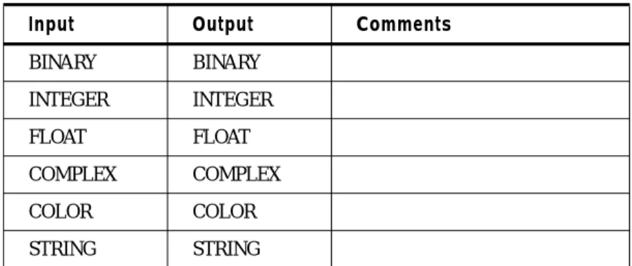
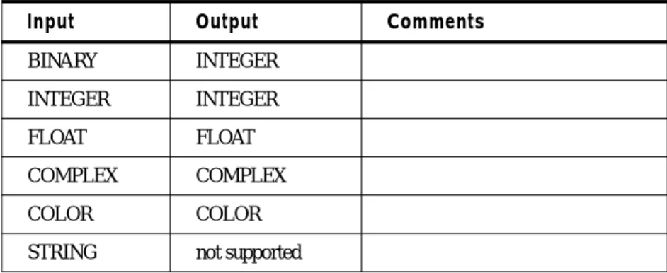
Expressions are the basic building blocks of most Modeler statements. Expressions consist of constants and variables linked together by operators and functions. Every expression represents an object in the Modeler. An expression has adata type and anobject type. The data type and object type for an expression are determined by the types of the constants and variables it is built from, together with theStandard Rules for combining types for each operation or function involved.It is possible to create expressions which have data and object type combinations which are not supported in variabledeclarations, such as color matrices and string rasters.
Constants Constants areSCALAR objects with a fixed value. Constants may be any data type. There are six types of constants:
• Binary • Integer • Float • Complex • Color • String
Each type is explained in the following: Binary Constants
Integer Constants
Any numeric value between -2,147,483,648 and 2,147,483,647 which does not contain a decimal point or scientific notation is an integer constant.
Examples:
601 -43
Float Constant
A numeric value containing a decimal point, in scientific notation, or outside the 32-bit signed integer range.
TRUE value of 1 or "true" logical value
DEFAULT value of 1 or "true" logical value