1
Cooking Systems using Aluminum Foam
Senior Project by: Ryan Mizukami
Advisor: Dr. Nathan Heston Administration: Department of Physics,
California Polytechnic State University, San Luis Obispo
2
Abstract
In developing countries, the use of wood burning fires for cooking is cause for illness and death. With this in mind, research was conducted to develop a solar cooking device capable of cooking
2 𝑘𝑔 of soup within 15 mins in order to reduce the negative impacts of cooking with wood.
Current methods of solar-based cooking, such as solar concentrators and solar tube ovens, are impractical. A small 100 𝑊 solar panel is a cost-effective way to produce energy but will not produce enough power to cook within a reasonable amount of time. Even if it is assumed that all of the energy produced by the panel is transferred into the soup, it will take about 2 ℎ𝑜𝑢𝑟𝑠 to bring it to a boil. To allow for the use of solar panels, thermal batteries utilizing phase change materials were researched. Thermal batteries can store energy produced throughout the day and release it when the user is ready to cook. In solar-based technologies, a common substance used as a phase change material to store is erythritol. Erythritol is a sugar-substitute that has a heat of
fusion ranging from (315 − 379.59) 𝐽/𝑔 but it also has a low conductivity at 0.733 𝑊/𝑚𝐾
when it is a solid. Due to low conductivity, if a thermal battery is made with only erythritol the rate of heat transfer will rapidly decrease to an unusable power. This is caused by a layer of solid erythritol that hinders heat flow. To increase the thermal conductivity, the battery can be laced with a metallic foam. Production of the suggested battery was not possible so a weighted average
for the conductivity was determined to be 71.6 𝑊/𝑚𝐾. The new conductivity allows for a rate
3
Table of Contents
1. Introduction ... 4
1.1. Commonly Seen Cooking Design ... 4
1.2. Background on Heat Transfer ... 6
1.3. Metallic Foam ... 10
1.4. Experiment ... 13
1.5. Thermal Batteries ... 15
1.6. Application of Metallic Foams Within Thermal Batteries ... 16
2. Usages ... 18
2.1. Current Alternatives to Gas Cooking in Developing Countries ... 18
2.2. Replacement for Current Technology ... 18
3. Experimental Possibilities ... 20
3.1. Efficiency ... 20
3.2. Usage of Thermal Batteries ... 20
3.3. Suggested Testing of Solar Powered Cooker ... 21
4. Conclusion ... 21
4.1. Potential Usage of Unit ... 21
4.2. Heating System ... 22
4
1. Introduction
1.1: Commonly Seen Cooking Designs
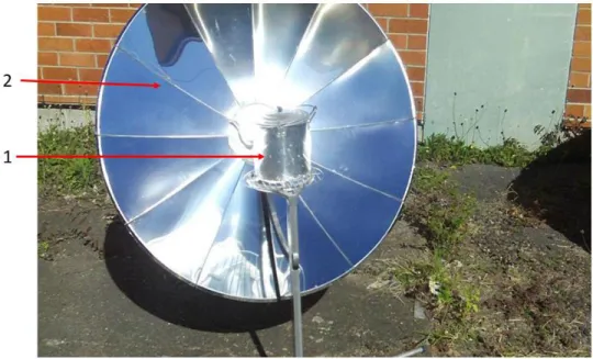
There are three main ways to use the sun’s energy to cook meals: solar concentrators, solar tube ovens and solar panels. Solar concentrators work with the concept of taking a large area of sunlight and focusing it towards a smaller area. A common design for this type of cooker utilizes mirrors and a single pot
Figure 1 – Picture of a solar cooker using a solar concentrator.1
The figure above shows a pot, labeled as 1, which contains the food that is intended to be cooked and a large mirror, labeled as 2, which directs a large area of sunlight onto the pot in order to heat what is inside of it. An advantage of this cooking method is that it takes almost all of the energy that is incident on the mirrors and directs it towards the pot; thus, heating the contents and allowing the food inside to be cooked. Another advantage is that these types of cookers do not need to be very elaborate. They can be made from carboard boxes that have a reflective surface such as aluminum foil, making them cheap to manufacture. Even though this method can utilize most of the energy that is incident on the mirrors, the solar concentrator needs to be constantly readjusted so that the sun is directed at the mirrors. Additionally, solar concentrators will only cook food during day light hours because they rely on a constant supply of solar energy. These units are often overlooked because of how large they need to be, how often they need to be readjusted, and they are not aesthetically pleasing.
Another method of solar cooking is through the use solar tubes. These consist of two concentric glass tubes that contain an absorbing material.2 The absorbing material captures heat from the
5 the unit insulated, allowing it to retain heat better than solar concentrator cookers. It is common to see solar tube ovens utilize solar concentrators because the tubes have a small amount of surface area that can be exposed to the sun at a time.
Figure 2 – Picture of a GoSun Solar Tube Oven.3
In the figure above the solar concentrator, labeled as 1, collects the sunlight and focuses it on the solar tube, labeled as 2. A metal tray, labeled as 3, is placed inside of the concentric cylinders and is where the food intended to be cook is held. The GoSun solar tube oven shown in Fig. 2 has a capacity of 145 𝑜𝑧 or about 9 𝑙𝑏 of food. Much like cooking with solar concentrators, solar tube cookers gather energy from the sun and focus it on the absorptive layer. Additionally, the solar tube has a vacuum between the concentric tubes which acts as insulation and allows the unit to absorb and retain energy. Together, these make the solar tube oven highly efficient at gathering and storing energy from the sun.
A disadvantage to these units is that the tray that holds the food to be cooked is similar to a drawer. If food spills or gets smashed, it would be difficult to clean when compared to a standard pot. Just like the solar concentrator cookers, these units must be used outside, aligned with the sun and only act as solar cookers during day hours. Another disadvantage to the solar tube cooker is that they are expensive and average at $1.90 per Watt.3 This means that a cooker that
can output 200 𝑊 would cost about $400.
6 have a more normal cooking station. The wires that are attached to the solar panel can also be used to store energy within a battery to charge phones or power lights during night hours.
1.2: Background on Heat Transfer
The amount of energy needed to boil 2 𝑘𝑔 of water with an initial temperature of 20°𝐶 is
670 𝑘𝐽. If a 100 𝑊𝑎𝑡𝑡 solar panel is used and all energy produced is transferred into the water it will take 1.8 ℎ𝑜𝑢𝑟𝑠 to boil. This is too long to be used for cooking. An alternative way to utilize solar panels for cooking is to store energy throughout the day and then release it when cooking. One way to do this is by using a battery which stores the energy generated. The battery can then power the solar cooker when in use.
When looking at how to store energy in a battery, qualities such as capacity, cost, lifespan and the round-trip efficiency should be considered. Round-trip efficiency can be defined as the ratio of energy put into storage to energy retrieved from storage. A larger round-trip efficiency indicates less energy lost due to storage. Solar batteries are great at dispersing the energy that they have stored throughout the day but they do have a limited lifespan and averages $400 per
kilowatt hour (kWh).6 A more cost-effective way to store the captured energy is within thermal batteries that utilize Phase Change Materials (PCMs). Materials used as a PCM have a high
storage density around the phase change temperature7 and a long lifespan. An example of a
thermal battery is one made with erythritol.
There are two ways that PCMs can store energy: by changing their temperature and by changing their phase. Looking at the equation for heat required to change a material’s temperature
𝑄 = 𝑚𝑐Δ𝑇, (1) where 𝑚 is the mass of the material, 𝑐 is the specific heat of the material, and Δ𝑇 is the change in temperature of the material, the amount of heat required to change the temperature of a material is dependent on how much the temperature has changed. A larger temperature change will require more heat. The relationship between heat and changing phase is defined as
𝑄 = 𝑚𝐿, (2) where 𝑚 is the mass of the material and 𝐿 is the latent heat of the material. A good PCM will have the ability to store energy in both a change in temperature and a change in phase. This means that the material holds both a high specific heat as well as a high heat of fusion. It should also have a dependable freezing behavior such that it does not deform the container that it is housed within as it goes through phase changes. Some other qualities that can be considered are if the material is corrosive, if it will destroy the container that it is housed in, if the material is heavy so the unit cannot be easily transported and if the material is expensive.
7 Table 1 – Thermal Properties of Erythritol7
𝑐𝑠 [ 𝐽
𝑔𝐾] 𝑐𝑙[
𝐽
𝑔𝐾] 𝐿 [
𝐽 𝑔]
1.38 2.76 315 − 379.59
In Table 1, 𝑐𝑠 is the specific heat when erythritol is a solid, 𝑐𝑙 is the specific heat when erythritol
is a liquid and 𝐿 is the latent heat of erythritol. As stated above, erythritol has fairly good heat storage through both the specific heat as well as the phase change process. By using the energy gathered from the solar panels, resistor-based heating elements will melt the PCM and charge the thermal battery. After the battery is charged, the heat can be transferred from the battery to the food by placing the two in contact.
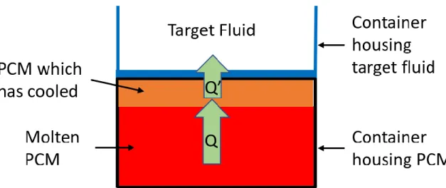
Figure 3 - Contained PCM when it is still molten in contact with a container housing target fluid.
8 Figure 4 -Contained PCM after some has cooled creating a barrier.
After the barrier is formed, the rate of heat transfer, in Watts, that is transferred from the molten PCM to the water will be reduced. The expression of heat transfer by conduction is
𝑄̇ =Κ𝐴Δ𝑇
𝑑 , (3)
where 𝑄̇ is the time rate of change of heat, Κ is the thermal conductivity of the material, 𝐴 is the surface area of the objects in contact, Δ𝑇 is the temperature difference between the water and the molten PCM and 𝑑 is the thickness of the material. In Fig. 4, 𝑑 is the thickness of the solid erythritol that separates the molten PCM from the container housing the water. The longer the unit is in use, the more energy is transferred from the PCM to the water, thus increasing 𝑑. For erythritol, the thermal conductivity of the solid state and the liquid state are on the same order of magnitude and can be seen in the following table
Table 2 – Thermal Conductivity of Erythritol7
Κ𝑠 [
𝑊
𝑚𝐾] Κ𝑙 [
𝑊 𝑚𝐾]
0.733 0.326
9 A wide 3-quart stock pot has a diameter of about 10 𝑖𝑛 or 0.254 𝑚 and a thickness of 1.5 𝑚𝑚. To determine if the pure erythritol battery would be reasonable for cooking, Fig. 3 will be
utilized. When cooking a boiling substance, the temperature difference between the molten PCM and the water will be about 20 𝐾. The molten erythritol and the container housing the water are separated by a layer of solid erythritol. Using Eqn. 3, which describes the rate of heat transfer through conduction, the output of the battery can be found. Unit conversions to the data on the stock pot must first be performed.
𝑑𝑖𝑎𝑚𝑒𝑡𝑒𝑟 = 10 𝑖𝑛 = 0.254 𝑚
𝐴 =𝜋𝑑
2
4 =
𝜋 (0.254 𝑚)2
4 = 0.0507 𝑚
2
𝑑 = 𝑡ℎ𝑖𝑐𝑘𝑛𝑒𝑠𝑠 𝑜𝑓 𝑠𝑜𝑙𝑖𝑑 𝑒𝑟𝑦𝑡ℎ𝑟𝑖𝑡𝑜𝑙 𝑙𝑎𝑦𝑒𝑟
Δ𝑇 = 20 𝐾
Now that all the information is properly formatted, the rate of heat transfer for pure erythritol battery, can be calculated for a thin 1 𝑚𝑚 layer of erythritol.
𝑄̇ =𝐾𝐴Δ𝑇 𝑑 =
(0.733 𝑚𝐾)𝑊 (0.0507𝑚2) (20𝐾)
0.001 𝑚 = 743 𝑊.
As heat is transferred from the molten erythritol, through the solid layer, into the water, the rate of heat transfer will decrease because the thickness of the solid layer increases. Fig. 4 is a good depiction to what could occur during this process. Eqn. 3 can again be used to see how the buildup affects the rate of heat transfer. First, if the layer of solid erythritol is 10 𝑚𝑚 thick, the rate of heat transfer is
𝑄̇ =(0.733 𝑊
𝑚𝐾)(0.0507𝑚2) (20 𝐾)
0.01 𝑚 = 74.3 𝑊.
Next, if the layer is 40 𝑚𝑚 thick, the rate of heat transfer becomes
𝑄̇ =(0.733 𝑊
𝑚𝐾)(0.0507𝑚2) (20 𝐾)
0.04 𝑚 = 18.6 𝑊.
10
1.3: Metallic Foam
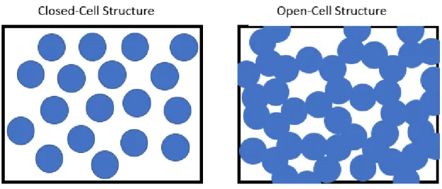
A metallic foam is a structure that is made of a metal with a large percentage of its volume as gas-filled pores. Within a closed-cell structure the pores are sealed whereas in an open-cell structure the pores connect creating an interconnected network8.
Figure 5 – Simple diagram of the two different structures of metallic foam adapted from Herring Paper9 where the blue area represents open space and the white area represent where metal is present.
Due to the ability to sustain large strains and stresses without fatal damage, closed-cell foams are often utilized in energy-absorption. Open-cell foams are often used for thermal dissipation or conduction because of their high thermal conductivity coupled with the surface area due to the
porous structure of the foam10. When working with a solar energy-based cooker using metallic
foams, it is vital to allow the PCM to fill the metallic foam so the open-cell network is utilized.
There are many techniques that can be used to produce both types of foams; however, because open-celled foam is used, the production of closed-celled foams will not be discussed. The common industrial method of production for open-celled foam is Foaming of Melts by Gas Injection.11 This process requires the injection of gases, typically nitrogen or argon, into the molten metal and then letting the structure cool and harden. These bubbles usually rise to the top of the molten metal fairly quickly causing the sample to lack the desired foam structure. A way to combat the speed of the rising gas is to increase the viscosity of the metal by adding ceramics. However, by doing so the strength of the sample may be lowered and become brittle. Some other ways to produce metallic foams are through Lost Foam Casting and the Soluble Material
Method.
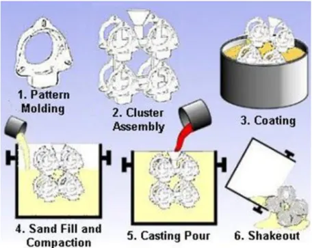
11 Figure 6 – Process of lost foam casting.12
In order to perform this method, the user must first create the shape of the object they are trying to make as depicted in Fig. 6, parts 1 and 2. Next, the assembled object is to be packed into the sand. This is most effective when given a pouring basin and a vent. As molten metal is poured, the evaporated foam has a channel where it can escape as described in part 5. Once the aluminum has cooled, it can be removed from the sand and it will have the shape of the foam that was previously in its place. Due to the difficulty of creating a structure, especially a porous structure that allows for flow of molten PCM out of foam, this method is not commonly used.
The more commonly used method to produce metallic foam, and the process that was used during this experiment is the Soluble Material Method. This requires the material to have a higher melting temperature than the metal being used to create the structure and the ability to be removed from the structure after the molten metal has set. A common material used is sodium chloride, also known as table salt, which is water soluble and easily accessible.13
12 The foam can be made with a furnace, vacuum chamber, table salt pellets, metal to form the structure, some inert gas, and a container for housing.
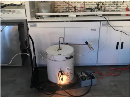
Figure 7 – Set up for creating metallic foam.
The vacuum chamber and the container both need to be made of a metal that has a much higher melting point than the target metal. Steel is commonly used because of its high melting point. In this experiment, a stainless-steel container was used to hold the salt and aluminum because
stainless steel has an approximate melting point of 1400°𝐶 and aluminum has an approximate
melting point of 700°𝐶.
13
1.4: Experiment
Figure 8 – Process to manufacturing using the Soluble Material Method.
After the materials needed are obtained, the process shown in Fig. 8 can begin.
1. Salt is poured into the stainless-steel container and the aluminum is placed on top.
Figure 9 – Aluminum atop a bed of salt then placed into the vacuum chamber.
The whole container is inserted into the vacuum chamber and then sealed. After the vacuum chamber is placed into the furnace, a vacuum is activated until a pressure of about 50 𝑡𝑜𝑟𝑟 is achieved. The furnace can now be powered to heat the salt and aluminum. Using a Proportional-Integral-Derivative (PID) controller, which monitors and regulates the internal temperature, the mixture will rise to about 700 degrees Celsius.
14 As seen in Fig. 7, there is no way to see inside the vacuum chamber to check if the salt has melted unless the lid of the furnace is removed and the vacuum chamber is unsealed. This is impossible at the working temperature, so the process needs to be done multiple times in order to ensure the proper temperature was maintained. It was found that the sample needs to be heated to 700°𝐶 and left there for 2 ℎ𝑜𝑢𝑟𝑠 and 30 𝑚𝑖𝑛𝑢𝑡𝑒𝑠 for the aluminum to completely melt.
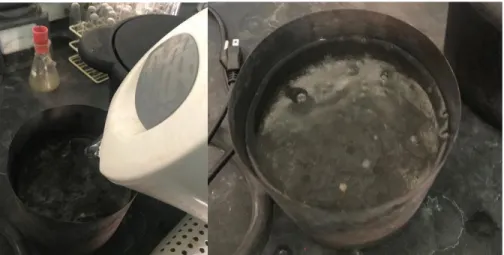
3. The chamber is then cooled and water is poured into the container to dissolve the salt. It was found that heating the water helped with the removal of the salt structure.
Figure 10 – Water being added to the sample to dissolve the salt from the structure.
4. After the salt has been dissolved, the sample can be extracted from the mold.
Figure 11 – Completed metallic foam.
It is then rinsed to ensure all the salt was removed and the density of the sample was calculated. Measurements such as height, diameter, and weight were recorded and used for calculation.
Next, this value was compared to the known density of Aluminum, 2.7 𝑔/𝑐𝑚3. The sample had a
15 𝑉 =𝜋𝑑
2
4 =
(3.7𝑐𝑚)(𝜋)(13.8𝑐𝑚)2
4 = 553.4 𝑐𝑚
3
𝜌𝑠𝑎𝑚𝑝𝑙𝑒 =
430𝑔
553.4 𝑐𝑚3 = 0.78
𝑔 𝑐𝑚3
Finally, a ratio between the density of the sample and the density of aluminum was determined. For the sample above, the calculation was,
𝜌𝑠𝑎𝑚𝑝𝑙𝑒
𝜌𝐴𝑙 =
0.78 𝑔/𝑐𝑚3
2.7 𝑔/𝑐𝑚3 = 0.288.
A value of 0.288 meant that the produced sample had a density that was about 29% of a sample
of aluminum with the same size and shape.
1.5: Thermal Batteries
Thermal batteries are devices that store and release thermal energy. They have many different designs; however, the basic principle is the same for all. They are devices that utilize materials in order to store energy for later usage.9 These devices can also be used in the opposite way where
16 Figure 12 – Diagram showing a GHEX unencapsulated thermal battery.
Next, the encapsulated thermal battery is one where the material that is storing the energy is isolated from its surroundings. This means that the ability to store and dissipate heat is entirely dependent on the material itself. A key factor in encapsulated thermal batteries is the Volumetric Heat Capacity (VHC) which is the volume specific heat capacity. If a material has a high VHC then it means that it can store large amounts of heat with less volume.15 Similarly to the mass dependent heat capacity, the volumetric heat capacity will vary with both state and temperature of the material. Generally, water is chosen due to its large heat capacity and availability. However, if there is a system that cannot contain the expansion of water when it freezes or a wider temperature range is required, then another material can be used.
Lastly, the PCM based thermal battery is one where materials change phase from a solid to a liquid (freezing), a liquid to a gas (evaporating), or a solid to a gas (sublimation). During these processes a large amount of energy is required but the temperature of the material remains constant. For this type of battery, the amount of heat that is needed to change the phase of a material is typically larger than the amount of heat needed to change the temperature of the same material from room temperature to its melting temperature. This is true for erythritol and why it can be used as a medium to store energy for a PCM thermal battery.
1.6: Application of Metallic Foams Within Thermal Batteries
17 rate of change of heat is inversely proportional to the thickness of the material. Additionally, as time goes on, the thickness of the layer will increase and the heat flow will decrease even more,
making the cooker less likely to cook food. As shown above, when there is a 5 𝑚𝑚 layer the rate
of heat transfer is 29% of its initial rate.
As it can be seen from Eqn. 3, the heat flow is proportional to the contact area of the two
surfaces and again inversely proportional to the thickness of the layer that the heat needs to flow through. The addition of metallic foam can increase the contact area between the two surfaces as well as decrease the thickness of the layer that the heat needs to travel through.
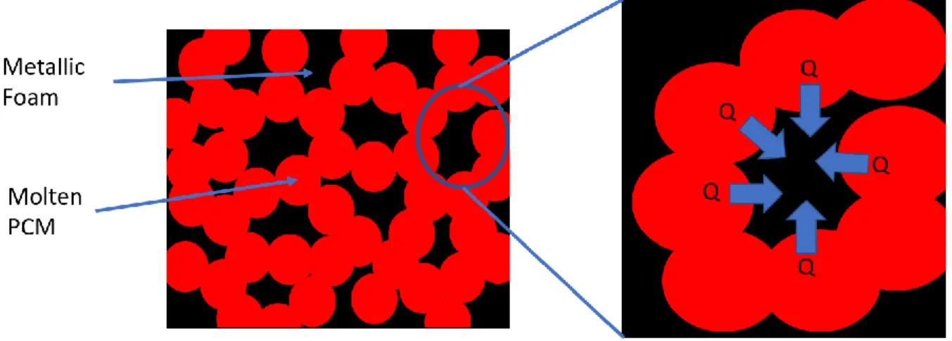
Figure 13 – Addition of metallic foam increasing efficiency.
Fig. 13 shows that when metallic foam is used with PCMs the surface area that allows heat transfer increases because each cell has molten PCM within it. Another consequence of using the foam is that the thickness of the material that the heat needs to travel through is minimized. The
thermal conductivity of aluminum is 237 𝑊/𝑚𝐾 so if it is laced within the PCM the overall
conductivity of the material will also rise.
An estimation for the thermal conductivity of the new battery was calculated through a weighted average. Aluminum foam takes up 30% of the battery and the rest is filled with erythritol.
Κ = (0.3) (237 𝑊
𝑚𝐾) + (0.7) (0.733 𝑊
𝑚𝐾) = 71.6 𝑊 𝑚𝐾
The new conductivity can be used within Eqn. 3 to find what the rate of heat transfer will be when metallic foam is integrated into the battery. When there is a 10 𝑚𝑚 layer of solid erythritol, the rate of heat flow becomes
𝑄̇ = (71.6 𝑊
𝑚𝐾)(0.0507 𝑚2)(20 𝐾)
18 When there is a 40 𝑚𝑚 layer of solid erythritol, the rate of heat transfer becomes
𝑄̇ =(71.6 𝑊
𝑚𝐾)(0.0507 𝑚2)(20 𝐾)
0.04 𝑚 = 1815 𝑊.
Calculations confirm the rate of heat transfer is significantly higher when aluminum foam is introduced into the battery. A larger rate of heat transfer will decrease the amount of time needed to cook food.
2: Usages
2.1 Current Alternatives to Gas Cooking in Developing Countries
About half Earth’s population rely on biomass and coal as sources of energy to cook and do not have access to the clean gas burning stoves that are commonly used in countries like the United
States of America.17 The most common ways to cook food are: roasting, boiling, steaming,
baking and frying. In order to cook, many people living in third world countries use wood fires to get the energy needed. A downside to wood fires is that they create a large amount of smoke and when cooking is done indoors large amounts of particles from incomplete combustion,
carbon monoxide, and other toxic products can lead to health issues.16 Both the women who
traditionally do the cooking as well as small children who are in the homes are subject to the possibility of contracting respiratory problems.
2.2: Replacement for Current Technology
19 Figure 14 – Proposed design of solar cooker.
This design has the inner container holding the fluid being used to cook, often water. It is encased inside another container with the PCM, metallic foam and has heating elements placed throughout it. The heating elements will utilize Direct Current (DC) electricity generated from a solar panel and supply the necessary energy to push the PCM through the phase change. The last layer is an insulating layer that surrounds the whole unit. The unit will be able to be charged as long as the solar panels supply electricity to the heating elements regardless of water being present in the main container.
If it is assumed that the unit will have 1𝑘𝑔 of PCM and will go through the phase change to cook soup at 100 °𝐶, using the values in Table 1, the amount of energy available is
𝑄 = 1 𝑘𝑔 ×1000 𝑔 1 𝑘𝑔 ×
1.38 𝐽
𝑔 𝐾 × (120 − 100) = 27,600 𝐽 = 27.6 𝑘𝐽.
Erythritol has a range of values for its latent heat and so if the average value is taken then when the PCM goes through the phase change process it will have
𝑄 = 1 𝑘𝑔 ×1000 𝑔 1 𝑘𝑔 ×
347.29 𝐽
𝑔 = 347295 𝐽 ≅ 347 𝑘𝐽.
20
3. Experimental Possibilities
3.1: Efficiency
The main goal of this device is to provide a way for people in developing countries to cook food while avoiding the dangers of using wood burning fires. However, if the cost to install and utilize the cooker is too large, the product will not be used. Due to the lack of moving parts and simple insulation of the outer layer, the maintenance for the system will be minimized. Additionally, solar panels can allow for the cooking device to be powered at a low cost. By adding additional solar panels, the amount of generated power can be increased.
An important thing about the metallic foam is that after it is created the thermal conductivity must remain high. Pure sodium chloride should be used to ensure no chemical reactions occur during manufacturing. There also must be good thermal conductivity between the container housing the PCM and the metallic foam that is within it. Using a thermal epoxy allows good thermal conductivity between the two materials as well as securing the foam to the container.
3.2: Usage of Thermal Batteries
The proposed solar cooker makes use of a single large thermal battery in the form of a cookpot that contains PCM and aluminum foam. It is used to store thermal energy to create a hot surface as the day progresses. It can also be utilized at night while the solar panels are not collecting energy. This means the efficiency of the thermal battery is vital to the operation of the unit as a whole. A way to test the efficiency and seek to improve the system is that each thermal battery can be connected to a heating element which charges the battery and then letting it transfer its stored energy to some mass of water. Different qualities of the battery that can be changed are9:
- Pore Size: the size of salt crystals which are used in the production of metallic foam
- Pore Density: how many salt crystals per volume
- Shape of Battery: Just flat at the bottom or encases the inner container as shown in Fig. 14
- Type of PCM within the metallic foam
- Material of the foam itself: Copper vs Aluminum
21
3.3: Suggested Testing of Solar Powered Cooker
Experimentation of the cooker is simple after the specifications are finalized. A good start is to determine how much PCM is needed to store the required energy to cook a meal. From this determination the unit can be assembled to hold the required amount of PCM. For example, 1110 𝑘𝐽 of energy are needed to cook 2 𝑘𝑔 of soup. If erythritol is used, 2.25 𝑘𝑔 of PCM is needed. Next, the cooker must be hooked to a DC generator and the heating elements powered for a given amount of time. This is followed by water being put into the main container and then measured to see how much the temperature of the water changes. Changes that could be made after initial testing are the amount of power supplied and how long the heating elements are powered.
Data that should be recorded includes
- If heating from the PCM is uniform throughout the unit
- The rate that heating occurs
- How long it takes to fully charge the unit
- The maximum temperature the inner container can achieve
While testing is being completed, the qualities that were adjusted before can be changed to better fit the final design. An example is if the thermal battery is too large then the solar panel might not be able to properly supply enough power to charge it. Conversely, if the thermal battery is too small then it might not be able to store enough heat energy to properly cook food. The total cost of the unit still needs to be kept in mind during the adjustments because if it becomes too high then it will not be bought.
4. Conclusion
4.1: Potential Usage of Unit
22 gather the required energy. If a large solar panel, rated at 200 𝑊𝑎𝑡𝑡𝑠, is used then it will only need 1.54 hours of sunlight to gather the same amount of energy. Both of these times are practical because we have about 8 hours of day light thus allowing for multiple charges of the thermal battery if needed.
4.2: Heating System
An issue of using a solar powered cooker is that it only gathers energy during sunlit hours. If the device is to be used during the night, the addition of thermal batteries can be used to store energy for heating when the solar panels are not collecting energy. Due to the intended purpose of this unit, which is cooking, a rapid release of the stored energy within the battery and an increase in the thermal conductivity with metallic foam is essential. Without the metallic foam, the purely erythritol battery with at least a 40 𝑚𝑚 layer will transfer energy at 18.6 𝐽/𝑠. A small
microwave has an output of 1000 𝐽/𝑠 so the battery without any metallic foam will not be able
to cook food at a reasonable rate. A battery that has both erythritol and the metallic foam, with the same layer, will be able to transfer energy at a rate of 1815 𝐽/𝑠. This is higher than both the small microwave and the pure erythritol battery.
23
5. Works Cited
1. Feminine, William. "Best Solar Cooker In 2019 (Top 10 Reviews)". Renewable Energy Picks,
2020, https://renewableenergypicks.com/best-solar-cooker/.
2. "Evacuated Tube Collector For Solar Hot Water System". Alternative Energy Tutorials, 2020,
https://www.alternative-energy-tutorials.com/solar-hot-water/evacuated-tube-collector.html.
3. "Gosun Fusion-Manual_V2_ENG.Pdf". Gosun.Com, 2019,
https://www.dropbox.com/s/u5g6ih8tv3cup1a/GoSun%20Fusion-Manual_V2_ENG.pdf?dl=0.
4. Cengiz, Mehmet Sait, and Mehmet Salih Mamiş. "Price-Efficiency Relationship For Photovoltaic
Systems On A Global Basis". International Journal Of Photoenergy, vol 2015, 2015, pp.
1-12. Hindawi Limited, doi:10.1155/2015/256101.
5. "Top 10 Cheapest (Best Value) Solar Panels - Energy Informative". Energy Informative, 2020,
https://energyinformative.org/cheapest-best-value-solar-panels/. 6. "Cost Of Solar Batteries | Energysage". Energysage.Com, 2020,
https://www.energysage.com/solar/solar-energy-storage/what-do-solar-batteries-cost/#:~:text=Solar%20batteries%20range%20from%20%245%2C000,installation%20or%20addit ional%20necessary%20equipment.
7. Höhlein, Stephan et al. "Thermophysical Characterization Of Mgcl2·6H2O, Xylitol And Erythritol
As Phase Change Materials (PCM) For Latent Heat Thermal Energy Storage (LHTES)". Materials
(Basel), vol 10, no. 4, 2017, Accessed 3 June 2020.
8. Liu, Peisheng, and Guo-Feng Chen. Porous Materials. Elsevier, 2014.
9. Herrin, Hunter. "Solid State Refrigeration Units Exploring Thermoelectric Heat Pumps And Metallic Foam". California Polytechnic State University, San Luis Obispo, 2018.
10. Aref, Hassan, and J. W Phillips. Mechanics For A New Millennium. Kluwer Academic Publishers,
2005, pp. 57-74.
11. Banhart, John. "Manufacturing Routes For Metallic Foams". JOM, vol 52, no. 12, 2000, pp.
22-27. Springer Science And Business Media LLC, doi:10.1007/s11837-000-0062-8.
12. The Lost Foam Casting Process: Part One :: Total Materia Article". Totalmateria.Com, 2020,
https://www.totalmateria.com/page.aspx?ID=CheckArticle&site=ktn&NM=387.
13. Jinnapat, Appichart, and Andrew Kennedy. "The Manufacture and Characterisation Of Aluminum Foams Made By Investment Casting Using Dissolvable Spherical Sodium Chloride Bead
Preforms". University Of Nottingham, 2011.
14. "Underground Geo Heat Exhanger Types (GHEX)`". Californiageo.Org, 2020,
https://www.californiageo.org/geothermal-basics-ground-heat-exchangers/ground-loop-ghex-types/. Accessed 7 June 2020.
15. "Volumetric Heat Capacity - An Overview | Sciencedirect Topics". Sciencedirect.Com, 2020,
https://www.sciencedirect.com/topics/engineering/volumetric-heat-capacity.
16. Mbatchou Ngahane, Bertrand Hugo et al. “Effects of cooking fuel smoke on respiratory symptoms
and lung function in semi-rural women in Cameroon.” International journal of occupational and
environmental health vol. 21,1 (2015): 61-5. doi:10.1179/2049396714Y.0000000090
17. Atitebi, Ayomide. "In Africa, Many Women Die Of Pollution From Cooking | Climate
Tracker". Climate Tracker, 2020, http://climatetracker.org/in-africa-many-women-die-of-pollution-