I
NVERTED
F
LUORESCENCE
M
ICROSCOPE
F
INAL
D
ESIGN
R
EPORT
P
RESENTED BY
Trevor Brown
[email protected]
Makenzie Kamei
[email protected]
Eduardo Miranda
[email protected]
Enoch Nicholson
[email protected]
California Polytechnic State University
San Luis Obispo
Spring 2020
6-5-2020
P
REPARED FOR
Benjamin Hawkins
Hans Mayer
ii
Statement of Disclaimer
iii
A
BSTRACT
The Inverted Fluorescence Microscope senior project team at Cal Poly, San Luis Obispo designed, assembled, and tested a proof-of-concept inverted fluorescence microscope for the university’s Microfabrication Laboratory. Administrators of the laboratory wished to use fluorescence for research and experiments involving cell growth and flow visualization on the micro-scale, and did not have the budget to purchase one of the costly commercially available options. The scope of this design challenge was to produce a low-cost inverted fluorescence microscope employing available optical components and additional readily sourced parts to expand the use of fluorescence microscopy accessible to undergraduate students in the Microfabrication Laboratory.
iv
T
ABLE OF
C
ONTENTS
Abstract ... i
Table of Contents ... i
Table of Appendices ... i
Table of Figures ... i
Table of Tables ... i
1
Introduction ... 1
2
Background ... 1
2.1
Customer Research ... 1
2.2
Product Research ... 2
2.2.1
Nikon Ti-2E ... 2
2.2.2
OPTIKA IM-3 ... 3
2.2.3
Olympus IXplore Standard ... 3
2.2.4
Motic AE31 and Zeiss Primovert iLED... 4
2.2.5
DropletKitchen ... 4
2.3
Patent Search ... 6
2.4
Technical Research ... 7
2.4.1
Books and Book Chapters ... 7
2.4.2
Journal Articles ... 8
2.4.3
Web Resources... 10
2.5
Standards and Regulations ... 10
2.6
3D Printing ... 11
3
Objectives ... 11
3.1
Design Considerations... 12
3.2
Quality Function Deployment ... 13
3.3
Engineering Specifications and Risk Assessment ... 13
4
Concept Design Development ... 15
4.1 Process ... 15
4.1.1 Functional Decomposition ... 15
4.1.2 Concept Sketching ... 16
4.1.3 Concept Modeling ... 16
4.1.4 Sponsor Feedback ... 17
v
4.2.1
Light Source ... 18
4.2.2
Objective Lens ... 20
4.2.3
Mounting the Optics ... 20
4.2.4
Fluorescence Detection ... 21
4.3
Stage ... 23
4.3.1
Ideation ... 23
4.3.2
Proposed Manufacturing Process ... 24
4.4
Frame ... 25
4.4.1
Ideation ... 25
4.4.2
Selection Process ... 27
4.4.3
Possible Risks ... 27
4.5
Final System Integration ... 27
4.5.1
Concept CAD ... 27
4.5.2
Concept Prototype ... 29
4.5.3
Design Hazards / Potential Risks ... 29
5
Final Design ... 30
5.1
Optical System ... 30
5.1.1
Brightfield Mode ... 31
5.1.2
Fluorescence Mode ... 32
5.1.3
Mounting the Optics ... 34
5.1.4
Analysis... 38
5.2
Stage ... 39
5.2.1
Actuator Mounting ... 39
5.2.2
Spring Return System ... 40
5.2.3
Sample Holding ... 42
5.3
Electrical Controls ... 43
5.3.1
Actuator Hardware ... 43
5.3.2
Control System Wiring ... 44
5.3.3
Software Development... 47
5.3.4
Preliminary Testing ... 48
5.4
Structural Prototype... 49
5.5
Design Changes Post CDR ... 50
5.5.1
Modified Imaging System... 50
vi
5.6
Satisfaction of Specifications ... 52
5.7
Safety Considerations ... 53
6
Manufacturing ... 54
6.1
Procurement ... 54
6.2
Manufacturing ... 54
6.3
Assembly ... 55
6.3.1
Stage Mounting ... 55
6.3.2
Frame Assembly ... 56
6.3.3
Control System Integration ... 56
6.3.4
Optical Alignment ... 56
6.3.4
Remote Assembly ... 57
7
Design Verification ... 58
7.1
Prototype ... 58
7.2
Testing ... 59
8
Project Management ... 61
9
Recommendations ... 63
10
Conclusions ... 64
vii
T
ABLE OF
A
PPENDICES
Appendix A: House of Quality
Appendix B: Gantt Charts
Appendix C: Concept Sketches
Appendix D: Concept Models
Appendix E: Microfabrication Lab Inventory
Appendix F: Pugh Matrices
Appendix G: Table of Indicator Dyes
Appendix H: Concept CAD
Appendix I: Conceptual Bill of Materials
Appendix J: Bill of Materials
Appendix K: Engineering Drawing Package
Appendix L: Pseudo Code
Appendix M: Wiring Diagram
Appendix N: Actuator Control Code
Appendix O: Vendor Information
Appendix P: Vendor-Supplied Specification and Data Sheets
Appendix Q: Purchase List (As Presented to Sponsors)
Appendix R: Failure Modes and Effects Analysis
Appendix S: Design Hazard Checklist
Appendix T: Operator’s Manual
Appendix U: Test Procedures
viii
T
ABLE OF
F
IGURES
Figure 2.2.1. Nikon Ti-2e Inverted Fluorescence Microscope……….……2
Figure 2.2.2. OPTIKA IM-3 Inverted Fluorescence Microscope………....…….3
Figure 2.2.3. Olympus IXplore Standard Inverted Microscope………..…………..3
Figure 2.2.4. Motic AE31 and Zeiss Primover iLED Microscopes……….4
Figure 2.2.5. DropletKitchen microfluidic droplet generator………..……… ………4
Figure 2.3.1. “Microscope Especially Inverted Microscope” Patent……..………...7
Figure 2.4.1. Fluorescein fluorophore and filter spectral properties………..………..8
Figure 2.4.2. Kahle fluorescence image of endothelial cells………...9
Figure 2.6.1. Example 3D printer………...11
Figure 3.0.1. Boundary Sketch of Project Solution Space……….……….12
Figure 4.1.1. Decomposition of Project Scope ……….………..……15
Figure 4.1.2. Initial Stage Concept Drawing….……….……….16
Figure 4.1.3. Z-axis Transverse Concept Model ………17
Figure 4.2.1. Optical Pathway Sketch ………18
Figure 4.2.2. Broadband Emission Spectrum Comparison……….19
Figure 4.2.3. Beamsplitter Schematic Diagram………..22
Figure 4.2.4. Dichroic Mirror and Beamsplitter Transmission Spectra Comparison………….…22
Figure 4.3.1. Early Stay Concept Drawings………23
Figure 4.3.2. Conceptual Model of Stage.………..24
Figure 4.3.3. Promising Stage Image……….……….25
Figure 4.4.1. Breadboard and Cage Frames……….………...26
Figure 4.4.2. Cage Concept Model……….26
Figure 4.5.1. Concept CAD Model……….28
Figure 4.5.2. Conceptual Microscope Model……….……….29
Figure 5.1.1. Main Optical Components…..………..30
Figure 5.1.2 Brightfield Mode Light Path……….………..32
Figure 5.1.3. Fluorescence Excitation Light Path..………...………..33
Figure 5.1.4. Fluorescence Emission Light Path………..………..34
ix
Figure 5.1.6. Indicator Dye Comparison: Fluorescein vs. Alexa Fluor 488…………..…………..37
Figure 5.1.7. Objective Mounting Bracket FEA………...………..38
Figure 5.2.1. Stage CAD Model……….…..………..39
Figure 5.2.2. Stage Actuator Mounting ………..40
Figure 5.2.3. Spring Return Brackets………..41
Figure 5.2.4. Stage Pull Test Setup………....41
Figure 5.2.5. Plot of Springs in System Constraints.………..42
Figure 5.3.1. L293D Pinout Diagram……….………...………...43
Figure 5.3.2. Arduino Upgrades……...……….45
Figure 5.3.3. Wiring Diagram………...……….45
Figure 5.3.4. Joystick Orientation…...………...46
Figure 5.3.5. Arduino Mega Flow…...………...46
Figure 5.4.1. Structural Prototype………..49
Figure 5.5.1. Optics Changes Post CDR..………..51
Figure 5.5.2. Stage Plate Post CDR……..………..52
Figure 6.3.1. SolidWorks Model for Critical Design Review……….57
Figure 6.3.2. Remote Assembly……….58
Figure 7.1.1. Verification Prototype……..……….59
Figure 7.1.2. Verification Prototype Testing Setup...……….60
Figure 7.1.3. Brightfield Test Result...…..……….61
x
T
ABLE OF
T
ABLES
Table 2.2.1. Comparison of Products in Relation to Their Specifications..………5
Table 2.3.1. Patent Search Results………..……….……...….6
Table 3.3.1. Inverted Fluorescence Microscope Engineering Specifications..………...13
Table 5.3.1. Arduino Mega to L293D Pin Correspondence………....………...45
Table 5.3.2. Arduino Mega to Actuators Pin Correspondence ………...…………...46
Table 5.3.3. Arduino Mega to Joystick Pin Correspondence ………...…………...46
Table 5.3.4. L293D to Actuator Pin Correspondence……….………...…………...47
Table 5.5.1. Dovetail Imaging System Components……….………...…………...50
1
1
I
NTRODUCTION
The primary project objective was to create a low-cost inverted fluorescence microscope for use in the Cal Poly Microfabrication Laboratory. Our team was comprised of four undergraduate students studying Mechanical Engineering at Cal Poly San Luis Obispo. This project was brought to the department by Dr. Benjamin Hawkins and Dr. Hans Mayer of Cal Poly San Luis Obispo.
A fluorescence microscope imparts energy to a specimen injected with an indicator dye by illuminating it with a specific wavelength of light. This energy causes the indicator die to fluoresce, emitting light at a longer wavelength than the excitation light used. The fluorescent emission is sent through a filter cube, which blocks all wavelengths of light not desired for the selected dye used. Commercially available models of microscopes capable of fluorescence can cost upwards of $30,000. This high price necessitated the creation of a low-cost version to make fluorescence microscopy accessible to Cal Poly students. This microscope will allow students to perform research projects including the study of how fluids react within microfluidic channels as well as the inspection of cell growth.
The following report captures the results of the design process, detailing the background research conducted, the problem’s scope and requirements, a timeline for efficient project management, and documentation of the final design selected for each microscope subsystem based on extensive iteration, analyses, and testing.
2
B
ACKGROUND
Our project research was focused predominantly in three main categories: customer research, product research, and technical research. Customer research entailed sponsor meetings, investigation of the available workspace in the Cal Poly Microfabrication laboratory, and discussion of design goals and requirements. Product research involved comparing out-of-budget, commercially available microscopes as well as do-it-yourself style home projects to the desired quality and capabilities of our product. Most of our knowledge on the physics of fluorescence, the anatomy and components of microscopes, and the application of fluorescence microscopy was derived from technical research in the form of journal articles and textbook chapters.
2.1
C
USTOMER
R
ESEARCH
2
• Low cost (achieved by employing available components and making use of rapid prototyping) • Utilizes available camera, optical components, and filter set for proof-of-concept testing • Makes use of rapid prototyping for appropriate microscope parts
• Modular and adaptable for future projects • Changeable objectives
• Changeable filters (ability to switch cubes as well as individual filters) • Modular camera attachment (uses standard camera attachment port) • Swappable actuators
• Room for experiments
• Inverted configuration • Manual and computer control of stage
• Operable by 400-level student in the Microfabrication class
2.2
PRODUCT RESEARCH
Our goal was to design and create a low-cost microscope, but when searching for similar products, we quickly found that a majority of the commercially available research microscopes cost well over $5,000. However, we were able to collect plenty of valuable information regarding dimensions, tolerances, and specifications for stage and optical components from the online data sheets provided for these high-end microscopes.
2.2.1 Nikon Ti-2E
Figure 2.2.1. Nikon Ti-2E Inverted Fluorescence Microscope [1]
Currently, there are many inverted microscopes on the market developed by various companies. Each of these microscopes have more functions than what we are designing and at a higher cost. For example, Nikon has its Eclipse Ti-2 series inverted microscope [1]. The microscope has capabilities such as a large field of view at 25 mm and a Z-axis stabilizer to reduce vibrations in the system to maintain focus on the specimen. Being one of the more robust inverted microscopes, the Ti-2 series has a “fly-eye” lens within the epi-fluorescence* illuminator to ensure uniform illumination [1]. Impressively, the stage uses motorized and mechanical maneuverability on its main body, condenser, nosepiece and other components. As a final touch, Nikon added sensors to assist users and auto-detect errors to increase user performance.
3
2.2.2 OPTIKA IM-3
Figure 2.2.2. OPTIKA IM-3 Inverted Fluorescence Microscope [2]
OPTIKA is an Italian company that constructs microscopes in various configurations. Unfortunately, not much could be gathered from their specifications outside of their catalog. From the information found, OPTIKA’s IM-3 inverted microscope is capable of two types of fluorescence imaging: mercury unforced cooling luminescence and LED. Along with these fluorescence types, the IM-3 exhibits a fixed 250x160 mm stage which can be fitted to become mechanically maneuvered, if requested [2]. Other features can be added to the microscope such as a UV fluorescence protection plate and replaceable objectives for its 3-lens objective turret. OPTIKA has pushed for longevity with their microscope which is rated with a 65,000-hour lifetime on its X-LED illumination system along with reducing electricity by 90% with its 8W light source [2].
2.2.3 Olympus IXplore Standard
Figure 2.2.3. Olympus IXplore Standard Inverted Microscope [3]
4
2.2.4 Motic AE31 and Zeiss Primovert iLED
(a) Motic AE31 [4] (b)Zeiss Primover iLED [5]
Figure 2.2.4. Two inverted fluorescence microscopes (a) by Motic and (b) Zeiss
The AE31 microscope series by Motic is similar to the previous three microscopes in its technological capabilities. The main difference is the fluorescence imaging must be done using one of their attachments and three filter cubes to conduct epi-fluorescence imaging [4]. The AE31 has a large stage (200x260 mm) with the option to add auxiliary extension plates. Encouraging a large workspace, the AE31’s standard condenser has a working distance of 72mm which can be increased to 231mm if the condenser body is fully removed. Zeiss produced a similar microscope, in which they reduced the complexity for user to overcome with the Primovert iLED [5]. The Primovert iLED has Epi-Fluorescence capabilities and can use its integrated camera and the Labscope imaging app for the iPad™ to observe a specimen outside of the workspace.
2.2.5 DropletKitchen
A project similar to our potential design is produced by DropletKitchen. Each of the materials required are detailed on their website, downloadable for 3D printing or a listed to be purchased at a store. The light source is small high-powered LED and its structure is made of acrylic. The required optics consist of a lens with a focal length of 50 or 100 mm. The design is adaptable and can allow for a mechanical stage or camera holder [6]. Because large portions of the body are 3D printed, the cost of production is significantly lower.
5
The key specifications of each of the microscopes have been placed into Table 2.2.1 below. As stated previously, current state-of-the-art microscopes are expensive in comparison to what to be developed by our team. The closest microscope to our potential design is the microscope produced by DropletKitchen regarding cost. Some of the microscopes listed are not initially equipped with fluorescence microscopy capabilities. Because of this complication, the costs listed are the costs listed on each off their respective websites and quotes would be required to find the true price.
Table 2.2.1. Comparison of Products in relation to their specifications
Products Cost Specifications
Nikon Ti-2e $38,995
• LED light source
• Fly-eye lens for uniform illumination • Motorized and Manual 114x73 mm stage • Camera Port and motorizing focusing unit
OPTIKA IM-3 $4,706
• X-LED illumination system with a 50k hour lifetime • HBO or LED fluorescence
• Camera port with multiple adapters • 250x160 mm fixed stage
Olympus IXPlore
Unknow n.
• Motorized 114x75 mm stage
• Motorized long working distance universal condenser • Filter wheels and shutters
• 8 position motorized or encoded fluorescence mirror turrets
Motic AE31 $3,395
• 200 x 260mm Stage • Centering Telescope
• Condenser with a working distance of 72mm • Possible Epi-fluorescence with 3 filter cubes with
attachment
Ziess Primovert $5,190
• Epi-fluorescence
• Transmitted light brightfield • UV protection plate
DropletKitchen Varies
• Interchangeable objectives
6
2.3
P
ATENT
S
EARCH
Developing an acceptable baseline for the design process required investigating existing patents. Understanding what is patented and the ideas that have generated them is very important, especially when designing commercial products. While our team was not creating a product for market, researching patents related to fluorescence microscopy still very useful information. Patents contain important general ideas and communication strategies despite the lack of technical information. Descriptions of a patent are supposed to be general to provide less of a barrier of entry to understanding thus providing succinct descriptions, and useful graphical communication tools. Table 2.3.1 summarizes the results of our patent search. All the documents found related to high end, commercial, research grade instruments. The products that these patents described fall outside of the scope of this project, but the communication tools and general ideas were useful.
Table 2.3.1. Patent Search Results
Patent Title
Patent / Application
Number
Highlights / Description of Patent
Inverted Microscope Having A
Variable Stage Position [7] US 6160662 A
Patent by Nikon for an inverted microscope, not fluorescence. The figures illustrate
microscope component layout well.
Fluorescence Microscope [8] EP 1666947 B1 This is a fully enclosed and computerizes microscope.
Compact, High-resolution Fluorescence And Brightfield Microscope And Methods Of Use [9]
US 9494783 B2
This patent lays out important component relationships in its list of claims. It also has
informative schematics.
Microscope Especially Inverted Microscope [10]
US 2005/0099679 A1
This is a patent application for an inverted microscope. It has exemplary examples of
how to graphically communicate microscope form and function.
Inverted Microscope [11] EP 2003481 B1
This is a fully enclosed and compact microscope design. It has a removable cover
that allows for stage access. Inverted-design Optical
Microscope [12] US 4210384A
This patent is for a compact inverted microscope with a deployable light source.
7
Figure 2.3.1. Example of clear graphical communication of a microscope’slight pathway. This sketch was taken from US Patent Application Publication: US 2005/0099679 A1, “Microscope Especially Inverted Microscope” [10].
United States Patent, US 9494783 B2, for a “Compact, High-resolution Fluorescence and Brightfield Microscope And Methods Of Use” provides an extremely comprehensive list of 18 claims that overview every microscope component. This list also highlights critical relationships between components. For example, the patent describes its illumination and detection system as being “fixedly mounted relative to one another” [9]. The patent then continues to state that this relationship allows the whole system to move together. Details like this helped us highlight important features to include in our final design.
2.4
T
ECHNICAL
R
ESEARCH
Peer-reviewed journal articles, textbooks and chapters, and websites for various biomedical organizations provided substantial sources of technical knowledge when building familiarity with the principles of fluorescence microscopy. An understanding of how optical components work together to produce an image was paramount in the construction of a microscope, especially considering the available parts were not necessarily designed for fluorescence applications.
2.4.1 Books and Book Chapters
8
Figure 2.4.1. (a) Spectral properties of fluorescein, denoting excitation andemission spectral maxima, compared to (b) its particular corresponding filter set. [13].
In Fundamentals of Light Microscopy and Electronic Imaging (Chapter 11), Murphy and Davidson explore the characteristic quantities of fluorescence and specifications that determine the choice of fluorophore for a specific application, including spectral region, Stokes’ shift, quantum efficiency, photostability, and spectral profile of the illuminator [14]. Included is a table of the properties of commonly used fluorescent dyes, noting spectral excitation and emission maxima, the color of fluorescence, and the corresponding standard filter set. For our microscope, proof-of-concept testing is designed for a single filter set and complementary fluorophore, so the choice of dye or filter combination is not necessarily a heavy design consideration. However, understanding the main principles of how a fluorescence microscope operates to produce fluorescent images was knowledge that we deemed essential for creating a satisfactory product.
2.4.2 Journal Articles
In “An Inexpensive and Simple-to-Use Inverted Fluorescence Microscope: A New Tool for Cellular
Analysis,” Kahle accounts her fluorescence microscopy design challenge; it had similar goals and constraints to ours, including an emphasis on minimizing cost [15]. Kahle notes some of her discoveries:
• A light source must be of adequate intensity and spatial uniformity; an LED satisfies this requirement.
• LED light sources can have high emission angles, so it is important to collimate the beams before passage through the excitation filter.
9
Kahle’s microscope used a 40 objective lens at 1.8 fps (0.5 second exposure). She obtained images of appreciable quality; in the primary stages of conceptual design, we needed to determine our own specifications in relation to the 4 objective lens we purchased.
Figure 2.4.2. Bovine pulmonary artery endothelial cell images tagged with its appropriate fluorophore (MitoTracker Red CMXRos, Alexafluor 488 phalloidin) collected with Kahle’s inverted fluorescence microscope setup. [15].
“Portable, Battery-Operated Fluorescence Field Microscope for the Developing World,” recounts Miller and his team’s approach to a design challenge of devising and fabricating a simplified portable fluorescence microscope, implementing components and techniques, such as rapid prototyping, that minimize cost for more accessible use [16].
• Optical illuminating components held in alignment by a single housing component, which was SLA printed in ABS plastic.
• High magnification (up to 1000) and resolution were achieved in brightfield mode by use of a macro lens and a doublet (achromat) lens onto monochrome CCD imagers.
• Final product cost $480 USD, and reproduction is estimated at $230 USD.
Improvements to resolution can be made by the addition of a condenser lens and higher quality objectives, we considered the factor during our own design process.
In “Advances in the Design of the Inverted Prismatic Microscope”, MacArthur details components of one
10
2.4.3 Web Resources
“Molecular Expressions – Fluorescence Microscopy” is a website administered by Michael Davidson through a variety of links, images, articles, and applets, details processes of choosing light sources, aligning optics, troubleshooting, and optimizing microscope configurations [18].
Davidson details means through which to optimize microscope image quality and specifies causes for diminished performance.
• To achieve uniform brightness, known as Kohler illumination, proper alignment of arc lamps is crucial. We may need to follow this procedure if we decide to use the Xenon-arc lamp as excitation illumination.
• Tungsten-halogen lamps are useful for traditional brightfield illumination, while Xenon-arc lamps are better for fluorescence applications.
• Even the slightest overlap in spectral profiles of excitation and emission filters can reduce fluorescence.
• Objective lenses of lower magnification (longer focal length) produce brighter images.
“Infinity Corrected Optics,” an article featured on Microscope World organization’s website, examines the benefits of the advancements made in infinity-corrected objective lenses [19]. Purchasing such a lens was a heavy consideration when designing an optical path and eventually ordering parts; infinity correction allows for auxiliary components to be placed in the optical path without significantly compromising focus. Making this specification, however, increased the difficulty of sourcing an objective lens of appreciable quality while minimizing cost.
2.5
S
TANDARDS AND
R
EGULATIONS
Standards and regulations were considered to make sure that the new product was made properly and operates safely during the design process. These standards provide a designer with insight when creating a new design. Without standards and regulations, proper design base points are not apparent and prevent the assurance of design results are sound.
ASTM Standard E883-11 “Standard Guide for Reflected-Light Photomicrography” explains the requirements and possible routes for constructing a reflected light microscope. This standard lists the common methods and ratios used in microscopes of this nature, such as:
• Preferred magnifications
• How photomicrographs should be reproduced, so that someone viewing the photograph is able to tell what the photograph is and its magnification
• Optical systems, and how the components must interact to get the desired image • Light sources and filters, as well as how to illuminate the sample
• Focusing
• Film processing techniques for microphotographs,
11
2.6
3D
P
RINTING
Throughout the course of our project, we utilized 3D printing as a method of fabricating and iterating components. Specifically, we used this method of rapid prototyping to create concept models used in the concept prototype [22]. In addition, we created low-cost versions of mounting brackets used in various locations, such as the stage and overhead beam. Industry is widely using additive manufacturing techniques for rapid prototyping, with a variety of materials. Some 3D printers are capable of fabricating metal and ceramic parts, which proves to be unnecessary for our project because the material can cost a significant amount. Also, the components we used for our project did not require the properties that these materials offer. The 3D printer used for our project is a Fused Deposition Modeling (FDM) unit where the material is pushed through an electrically heated nozzle [21]. Typically, the material is a form of plastic such as Polylactic Acid and Acrylonitrile butadiene styrene, or commonly referred to as PLA and ABS respectively. Our project utilizes PLA, as it is widely available, offers adequate properties, and does not require a lot of post processing.
Figure 2.6.1. Example of a 3D printer similar to the one in the Micro-fabrication lab [23]
The 3D printer displayed in Figure 2.6.1 is similar to the 3D printer we have in possession. Stepper motors are used move the nozzle in two axes and the table in one independently. The software required to operate the 3D printer is a CAD software, like SolidWorks®, and 3D printer software to communicate between the computer and the printer itself. Another way to load a model into the printer is to upload the CAD file onto an SD card and load the SD card into the 3D printer. Through this simple process, fixtures and other components can be made with plastic.
3
O
BJECTIVES
12
Figure 3.0.1. Boundary sketch of our project solution space.3.1 D
ESIGN
C
ONSIDERATIONS
According to Dr. Mayer and Dr. Hawkins, the following considerations should be employed when designing the microscope:
• Low cost construction through rapid prototyping or using already acquired materials. • Open and Modular for interchangeability of parts such as optical filters and objectives.
• Infinity corrected optical components. In this case, infinity corrected means that image distance is set to infinity to create a parallel optical path to the camera without needing to account the objective’s optical distance.
• Modular camera attachment so multiple cameras can be interchanged with one another. • Large open space on stage for future experiments and to prevent obstructions.
• Consistency of focus while the stage travels.
• Computer driven actuators will work in tandem with the manual controlled portion of the stage. These actuators must also be able to be replaced.
13
3.2 Q
UALITY
F
UNCTION
D
EPLOYMENT
To ensure that we provided the best solution to the problem, we employed the use of the quality function deployment. The House of Quality contains sections for each of the questions asked pertaining to the project. The House of Quality has each section organized to display how each item influences one another. As shown in Appendix A,the “who” section details the customers of our project which are Professor Mayer, Professor Hawkins and 400 level students. Their wants and needs are detailed adjacent to the “who” section, with how each want ranks with each customer in terms of importance, in the “how” and “what” sections. These sections can be seen interacting through assigning correlations. Leading competitors are placed in the “now” section with their ranking determined on how well each satisfies customer needs. The competition is also compared to engineering specifications in the “how much” section through target values. The House of Quality allowed for a better view of what was asked by our sponsors and was used to determine the final specifications discussed in the next section.
3.3 E
NGINEERING
S
PECIFICATIONS AND
R
ISK
A
SSESSMENT
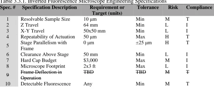
Engineering problems can be defined using specifications. They are used to identify and quantify important design considerations. Table 3.3.1 provides a list of the specifications that we believed were critical to defining our problem. Each specification has an associated risk level (high, medium or low). The level relates to the amount of difficulty we believed was present in meeting a specification. Low risk specifications could be met with simple initial design choices. This category is comprised of size and motion requirements. Medium risk specifications required a finer degree of component selection / design. For example, to achieve our target resolvable sample size, we needed to ensure we chose adequate optical components. High risk specifications identify areas that we knew needed special design consideration. These specifications were subject to a high degree of tolerance stack up and were difficult to satisfy without diligent consideration. The table also includes the values we hoped to achieve for each specification, an assessment of risk, and the method we intended to use to verify each specification. Each of the methods include inspection (I) and testing (T).
Table 3.3.1. Inverted Fluorescence Microscope Engineering Specifications
Spec. # Specification Description Requirement or Target (units)
Tolerance Risk Compliance
1 Resolvable Sample Size 10 μm Min M T
2 Z Travel 64 mm Min L I
3 X-Y Travel 50x50 mm Min L I
4 Repeatability of Actuation 50 μm Max H T
5 Stage Parallelism with Frame
0 μm ±25 μm H T
6 Clearance Above Stage 50 mm Min L I
7 Hard Cap Budget $3,000 Max M I
8 Microscope Footprint 2x3 ft Max L I
9 Frame Deflection in Operation
TBD TBD M T
10 Detectable Fluorescence Any Min M T
14
• Resolvable Sample Size
The sample size resolvable by the microscope is determined by the objective used. When using a 4X objective, this microscope should be able to detect a feature 10 μm in diameter.
• Z Travel This microscope was designed with one objective initially, but it has the travel flexibility to accommodate various objective sizes.
• X-Y Travel The microscope’s X-Y travel had to be large enough to fully utilize the range of our linear actuators (50x50 mm). This provided enough travel fully observe any microfluidics experiment.
• Repeatability of Actuation
The stage is positioned with two 850G Series Linear Actuators, which are repeatable to approximately 40 μm. To verify the final prototype’s actuation repeatability, we intended to create a test cycle in which the stage is moved to a variety of points, and then back to the start. The stage should be able to end within 50 μm of its starting position. During our last day of testing we qualitatively checked the system’s repeatability. A quantitative test was not possible.
• Stage Parallelism with Frame
It is extremely important for our microscope to maintain focus. To verify that our stage stays within 25 μm of parallel to the base. We hoped to verify that our system stays parallel by using a dial indicator (quantitative), and by observing if our microscope stays focused on a 50 μm deep microfluidic channel over a 50 mm travel. Due to time constraints this was not possible.
• Clearance Above Stage
Ample clearance must be left above the stage to allow for microfluidic tubing, and other experimental equipment. We were careful to design the upper gantry of the microscope with sufficient clearance.
• Hard Cap Budget
Minimizing costs wherever possible allowed us to spend what we have on higher quality optics. We fully utilized rapid prototyping to stay under budget.
• Microscope Footprint
Our microscope had to fit within the 2x3 ft optical bread board that we have been provided for construction.
• Detectable Fluorescence
Fluorescence detection is highly dependent of the camera and light source used. Any level of detectable fluorescence using the equipment currently available in the Microfabrication Laboratory is sufficient to verify that the optics are functional. Unfortunately, we were not able to purchase the components needed to test fluorescence imaging.
We believed that actuation repeatability and parallelism would be our two most challenging specifications to satisfy. Both were highly dependent on the quality of the components we use, and the level of precision with which they align. By identifying these risks early and considering them throughout the design process, we prevented them from presenting a problem.
15
4
C
ONCEPT
D
ESIGN
D
EVELOPMENT
This section overviews the idea refinement process used to converge upon a single design concept. This development process was applied to our project in three subsystems: optical pathway, microscope stage, and frame. During the ideation and design distillation phase, we quickly realized that due to the nature of the project, the design choices made for each subsystem had minimal interdependence; therefore, ideation for each subsystem was tackled individually and the best alternatives for each were chosen and developed further. Each optimized subsystem was then integrated into the final design. After defining the problem, establishing quantitative specifications, and identifying budget constraints, we were able to begin searching for microscope components and develop potential configurations to maintain progress towards a final design concept.
4.1
P
ROCESS
To generate as many ideas as possible before analyzing the strengths and pitfalls of each design concept, we followed a standard engineering design process. Functional decomposition, brainstorming and ideation, sketching, modeling, and meeting with sponsors to gain feedback promoted the eventual convergence upon a single concept design to move forward with. Due to the nature of this project, the process was applied to each of three subsystems, and then integrated into one final design.
4.1.1 Functional Decomposition
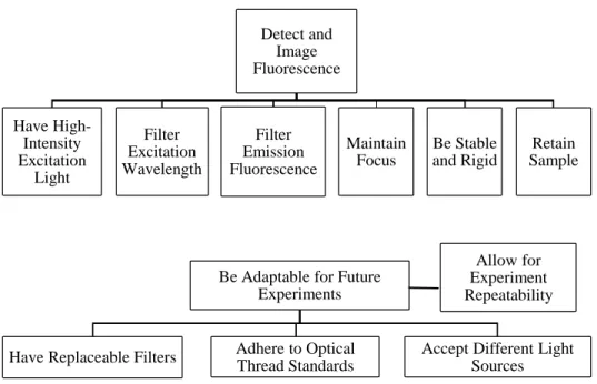
Prior to brainstorming and generating solutions, it was necessary to first identify the main functions that our final product will accomplish, determine their interdependencies, and define the critical subfunctions that would result in detecting and imaging fluorescence. The functional decomposition of our project is displayed below in Figure 4.1.1.
Figure 4.1.1. Decomposition of project scope into general functions, subfunctions, and dependencies. Detect and Image Fluorescence Have High-Intensity Excitation Light Filter Excitation Wavelength Filter Emission Fluorescence Maintain Focus Be Stable and Rigid Retain Sample
Be Adaptable for Future Experiments
Have Replaceable Filters Adhere to Optical Thread Standards
Accept Different Light Sources
16
4.1.2 Concept Sketching
In the context of our project, ideation began with group discussion and individual concept sketches for each microscope subfunction. From the ideation, an early design of the stage can be seen in Figure 4.1.2. Leaders for each respective subsystem illustrated two concepts and presented them to the group in a team meeting. Proposals were also brought to project sponsors for feedback and suggested improvements for design concept refinement. A comprehensive list of all concept sketches is detailed in Appendix [C].
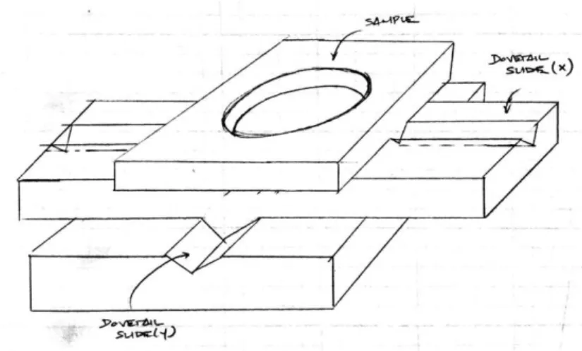
Figure 4.1.2. Sketch of one of our initial X-Y stage concepts implementing slides. Note: we are aware that the slides pictured are not dovetail slides.
4.1.3 Concept Modeling
17
Figure 4.1.3. A “quick and dirty” concept model of a z-axis traversingmechanism for maintaining focus on the sample of interest, constructed with plastic building bricks.
4.1.4 Sponsor Feedback
Ultimately, much of the decision-making process was facilitated by sponsor communication and feedback. We presented initial concepts for the optical pathway, stage, and frame to our sponsors, who would either confirm or suggest modifications based on budget and feasibility. Both the objective lens and the stage, our primary high-cost design components, needed to be found and purchased at a discounted price, prompting us to maintain continuous sponsor contact via email and meetings.
In the following sections, we detail solution concepts for each microscope subsystem, the design factors considered in the ideation process, and the selection of a single concept to proceed with using decision matrix analysis and controlled convergence.
4.2 O
PTICAL
P
ATHWAY
Ideation for the microscope’s optical pathway was rigid since there is little flexibility regarding required optical elements or alignment of these components. However, based on our previously defined engineering specifications and constraints implemented by our project sponsors and the availability of components, some decisions needed to be made concerning the light source, objective lens, filters, and corresponding indicator dyes to have the best chances of creating a final product capable of imaging fluorescence.
Prior to initial ideation and brainstorming, we took inventory of all the optical components available for use in the Microfabrication Laboratory and determined which additional components we needed to purchase and which we could manufacture or print ourselves. A listing the parts at our disposal is detailed in Appendix [E].
18
proof-of-concept testing. Shown in Figure 4.2.1 is a sketch of the target optical pathway devised from sponsor feedback and suggestion. The following subsections detail selection of specific components.
Figure 4.2.1. Sketch of the optical pathway agreed upon by
project team and sponsors.
4.2.1 Light Source
We envisioned the final inverted microscope being equipped with both brightfield and fluorescence capabilities; this required two different light sources and two optical pathways that do not interfere with one another. Brightfield illumination is simple – sufficient brightness can be achieved with one of the Fiber-Lite fiber optic illuminators in the lab, and the neck of the cable adapter can be secured with a collar-setscrew assembly for position adjustment.
19
to be captured by the camera. Further research confirmed that upon exciting the specimen, energy losses result in fluorescence with longer wavelength and much weaker intensity than its supplied excitation light.
Our final design employs the use of a single-wavelength LED and driver, which will provide a higher intensity light source than that of the broad-spectrum. The LED will provide only a single specified excitation wavelength. Despite this, the design can be adapted for different fluorophores and filter sets simply by replacing the LED with one of a different wavelength corresponding to that application. Figure 4.2.2 shows the excitation wavelength spectra of both light sources.
.
(a)
(b)
Figure 4.2.2. A comparison of (a) the broad-range emission spectrum of the Deuterium-Halogen lamp [24] and (b) the spectrum of a single-wavelength LED [25].
In future iterations of this microscope design, given an larger budget, it would be advantageous to utilize a high-power LED built for microscopy to bombard the specimen with greater intensity excitation light. ThorLabs sells its Solis Series LED’s for prices on the order of $1300.00 and accompanying drivers for $525.00. While this extends far outside of this project’s specified budget, a more powerful single-wavelength Solis LED or a white light Solis LED coupled with an excitation filter would result in higher intensity and more easily detectable fluorescence.
20
4.2.2 Objective Lens
Following extensive analysis of our budget and inventory of the optical components available in the Microfabrication Lab, it was resolved that a high-quality objective lens would likely be the greatest budget expense. Therefore, compiling a thorough list of viable options was crucial before converging on a final item to purchase.
Searches pursued the following criteria: • 10X Magnification
• Designed for Epi-Illumination • Infinity-Corrected
• Long Working Distance • Less than $1,000
• Common Thread Standard
The Mitutoyo Plan Apo 10X sold by Edmund Optics was one of the first objective lenses found that was in-range with respect to budget and met the desired specifications; this lens became the “datum” to which all other alternatives were compared to. A Pugh Matrix for selecting an optimal objective for imaging fluorescence using these criteria is included in Appendix [F]. The results obtained were acknowledged as a guideline for a final decision.
Ultimately, after discussing the listed options with our project sponsors, we concluded that the most practical step forward was to purchase a cheaper objective lens (under $100) from eBay for proof-of-concept and alignment purposes. We intend to replace it later with a higher quality, more expensive objective lens once the optical pathway and all other components are established.
Following this plan, we purchased the AmScope Fluor Plan 4X, which can later be upgraded to the Edmund Mitutoyo Plan Apo 10X or another AmScope with higher magnification. One caveat we needed to remain aware of was that AmScope objectives follow an older thread standard than the more current products; we chose to find an adapter for a different thread standard. Also, considering the smaller magnification objective had both a shorter length and working distance, we needed to allow for sufficient z-travel to accommodate a much larger, long working distance objective.
4.2.3 Mounting the Optics
Nearing the detail design phase, one of the greatest considerations before proceeding with a final product concept was the means by which the objective, filter cube, and other components of the optical train would be oriented and mounted under the stage.
The first concept was a simple machined aluminum block, with internal RMS threads on one end to mount the objective, external S1 threads on the other to fix the filter cube, and an 8-32 tapped hole on the bottom face to attach the optical assembly to a standard-series post so that it would be further fixed to a slide or to the breadboard table. After careful consideration, this option was ruled out due to the difficulty of manufacturing the fine threads necessary for interfacing to optical components. Cost of materials would be lower than commercially available options, but the cost of tooling would outweigh the alternatives greatly. It was also noted that a block would be not be as elegant as other options.
21
allow for the objective to be coupled to the filter cube. This assembly also required an RMS threaded collar to mount the objective, by which half of the threads would be occupied by the base of the lens, the other half by the adapter. This method was preliminarily determined to be the most cost-effective since one of the adapters is already available in the clean room; this would bring the expenses for coupling parts down to ~$37. However, upon further consideration, we decided that other options would better prevent any potential shifting of the optics.
Attachment of the objective lens and filter cube assembly by cage optical components ensures structural integrity of this section of the optical train due to multiple points of contact and the ability to fasten each cage rod using small setscrews. Another viable option is to use an RMS threaded cage plate to mount the objective and four 1/4" cage rods to attach this assembly to the filter cube, which is compatible with cage optical parts. A caged optical system is the most structurally sound of the three in a primarily vertical optical train; however, it was determined later in the design process that using an infinity-corrected objective allowed for much more flexibility in the design.
After consultation with Cal Poly Optics professor, Dr. Glen Gillen, we decided to mount only the objective in its vertical position and to fix all other optical components horizontally to the breadboard to minimize the number of components underneath the stage and mitigate the risk of misalignment, using a 45º plane mirror between them. Theoretically, an infinity-corrected objective allows an infinite distance from the shoulder of the objective (the typical location of the lens itself) to the tube lens; in practice, this distance is usually restricted to 100-200mm to minimize aberration, but this was still ample space to extend the optical train in a horizontal configuration.
To provide adequate rigidity and to prevent any rotation of the objective during microscope operation, we designed a 3-D printed bracket to hold an RMS-threaded mount and to interface with the z-axis focusing translation stage. A Pugh Matrix exploring the described design options is in Appendix [F] and specifics of this design are detailed in the Final Design Concept (Chapter 5).
4.2.4 Fluorescence Detection
To observe fluorescence, it was necessary to have a mirror at an oblique angle of incidence (typically 45) to efficiently reflect light in the excitation band and transmit light in the emission band [26]. In commercially available fluorescence microscopes, a dichroic mirror provides this additional filtering. Upon deliberation with our project sponsors, we decided to instead use a beamsplitter for our application for the following reasons:
(1) A 50:50 beamsplitter differs from a dichroic mirror in that it is not wavelength-selective; it simply splits a beam of light in two, transmitting half and reflecting half. Since beamsplitters are wavelength independent, they have the flexibility of working with any set of filters, improving the adaptability of our microscope for different samples and indicator dyes. A diagram of a 50:50 beamsplitter and differences in the wavelengths transmitted between the dichroic mirror and beamsplitter and can be seen in Figures 4.2.3 and 4.2.4 respectively.
(2) No additional filtering is required to further isolate the excitation light since we are using a single-wavelength LED light source.
22
Figure 4.2.3. Schematic diagram of how a 50:50 beamsplitter functions. 50%of the incident light is reflected 90 while 50% is transmitted [27].
(a) Dichroic Mirror (b) Beamsplitter
Figure 4.2.4. Comparison of the transmission spectra of (a) a short pass dichroic mirror (% transmission denoted by blue line) and (b) a 50:50 beamsplitter cube [25].
23
4.3
S
TAGE
The stage of a microscope is an essential piece of hardware. It rigidly locates the sample and allows the user to finely position it within observation field. Because the stage also serves as an experimental platform, it enables the microscope user to attach other experimental devices that must travel with the sample throughout observation.
4.3.1
Ideation
Our initial Functional Decomposition yielded four functions that related directly to the stage: rigidity, repeatability, motion, and sample retainment. Using these functions to guide the ideation process, we created concept sketches of the stage mechanism. Figure 4.3.1 show two of our earliest sketches.
-
-(a) Linear Rail with Optical Slide Block (b) Dual Optical Slide Block
- -
Figure 4.3.1. Two of the earliest concept drawings of the stage. Figure 4.3.1a shows a stage that rides on linear rails in one axis, and on an optical slide block in the other. The rail axis is driven by a stepper motor / timing belt, while the slide axis is driven by a linear actuator. The sample is held with an over-hung, old fashioned, mechanical stage (not drawn in detail). The stage in Figure 4.3.1b has both axes driven by linear actuators connected to optical slides. The stage is designed to hold a sample in a petri dish cantilever over the microscope optics.
24
-
-(a) Collapsed (b) Actuated
- -
Figure 4.3.2. This show two positions of the stage concept model that we created.
Our team utilized Pugh Matrices to settle on a direction forward for the stage. Because the functions have little interdependence, we were able to apply this design tool to stage form and actuation separately (included in Appendix F). They showed us that the best stage form utilized purchased optical slides. The other form options that we considered could not compete with the alignment ease, and axis parallelism that a purchased stage offers. Because a new stage is cost prohibitive, our purchasing options are confined to used equipment. We initially struggled to find viable used stage options, so we began to lean towards completely manufacturing the stage. Our first round of Pugh Matrices did not indicate a clear choice for stage actuation. Ball screws, optical actuators, and micrometers all produced the same score. After some review, we added a category for cost. This addition shifted the results, giving optical actuators the highest score.
We took our preliminary ideation findings to our sponsors for review and asked their thoughts on manufacturing a stage. They emphasized the importance of stage parallelism and raised valid concerns regarding our ability to achieve this specification with the tooling available to us. They also discussed the importance of having a large experimental platform to anchor experimental tools like micro fluidic lines. This led us to question our initial assumption that overhanging the sample was the best way to facilitate microfluidics experimentation. Hanging lines have the potential to catch and dislodge the sample. Without a large support platform, this could lead to damage of the optical components under the stage. Drawing from both our ideation results and sponsor comments, we decided that the best stage design involved retrofitting a used stage to use the linear actuators available in the Microfabrication Laboratory.
4.3.2
Proposed Manufacturing Process
25
• The addition of physical stops or limit sensors on each travel axis.
• The removal of the stage center to allow for inverted observation. We plan to fabricate removable plates for the stage center to allow for the adjustment of the viewing field.
• The attachment of our linear actuators to each stage axis. This may require the fabrication of coupling pieces.
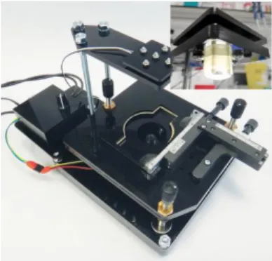
• The creation of threaded mounting holes on the stage surface.
-Figure 4.3.3. Image of one of the stages that we purchased. This option has a good deal of room underneath, and pre-aligned attachment points for actuators.
4.4 FRAME
Like the stage, a rigid frame is a necessity in a microscope’s reliability. The frame secures the components and allows the microscope to function. Experiments can also be secured onto the frame so the sample may be observed. This is especially important for this type of microscope, as often there are parts of an experiment that do not need to be directly observed through the lens.
4.4.1 Ideation
26
-
-(a) Breadboard frame (b) Cage Frame
- -
Figure 4.4.1. (a) Shows an optical breadboard which allows for components to be placed wherever they need to be in premade holes; (b) is a sample cage design for the frame, consisting of a cube-like structure that encases the entirety of the microscope, allowing for components to be attached to the outside. The breadboard is sturdy but has the possibility of being cluttered with components. The cage allows for vertical mounting but will not be as strong as the breadboard.
Following the design and purchase of the stage, we needed to include a way to have Z-Axis travel within our microscope. This can either be done by moving the sample up and down, or by moving the optical components below the stage up and down while maintaining the distances between the optical components.
After the initial ideation process, concept models were created to demonstrate basic ideas and assess functionality. We did not create a concept model of the optical breadboard, since these are readily available for purchase; therefore, we would not need to construct one should we decide on this design. Figure 4.4.2 shows a concept model of the cage-like frame.
-Figure 4.4.2. Concept model of cage-like structure for frame design. Shown with stage attached to the bottom rail, and brightfield light hanging from top shining on the
27
4.4.2 Selection Process
After taking inventory of the components available for our use, we found an optical breadboard, and decided to implement it in our design. We planned to incorporate an overhead frame, consisting of one beam connected to posts on either side and attached to the breadboard. The frame is be made of 80/20 T-slot aluminum and is attached to the base using brackets. We chose to incorporate the Z-Axis travel by moving the optical components beneath the stage. This was decided to alleviate the possibility of stretching or disconnecting the microfluidic lines that will be connected to the sample. This frame design is shown in the concept CAD model.
4.4.3 Possible Risks
Our frame design is relatively simple, with no moving parts. After analysis of the design, the only apparent risk or hazard associated with the frame is the breadboard. Because the optical breadboard is heavy, it provides a hazard if it were to fall on someone. To eliminate this risk, we thought about the breadboard on either a solid table surface or atop a cart that is weighted down.
4.5 F
INAL
S
YSTEM
I
NTEGRATION
Following the selection of the best design direction for each subsystem, these solutions were integrated into a final main microscope system. To illustrate our intended path forward, we built a conceptual SolidWorks model and a conceptual prototype from readily purchased materials.
4.5.1 Concept CAD
28
-(a)
-(b)
Figure 4.5.1. (a) Isometric view of Concept CAD model; (b) Side view of concept CAD model, showing details of fluorescence components and optical pathway.
29
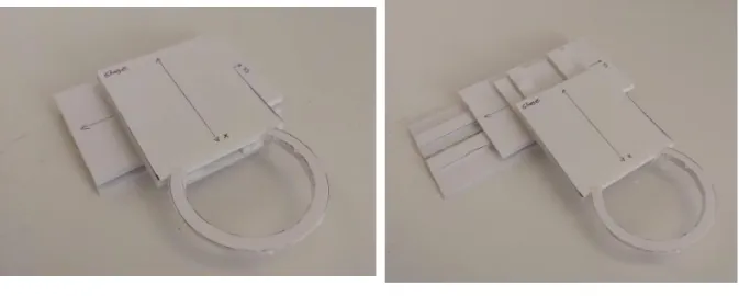
4.5.2 Concept Prototype
The CAD model proved to be useful starting point, but we understood what we wanted from the project by building a physical concept prototype, as shown in Figure 4.5.2. We built our model out of plywood, PVC, and PLA. The two processes that we used in the prototyping were 3D printing and laser cutting. This gave us an easily modifiable physical way to explore our design space. Right away we saw that we were not spatially confined. We had the room to place our stage slides wherever we needed on the breadboard. We also realized that it will be challenging to ensure that our stage has the clearance to reach full travel with large optical components underneath. We believed making the stage large or locating the actuation system away from the optics will be the best way to ensure sufficient travel.
(a) Isometric View (b) Front View
Figure 4.5.2. Image of the final Concept Prototype.
4.5.3 Design Hazards / Potential Risks
As we devised new design ideas and began to converge on a final concept, it became necessary to assess our solutions from a safety standpoint. Commercial microscopes are usually contained within a cast body, and so there are very few safety concerns to make note of. However, since the design we have decided to proceed with is more of an open design with the intent to ensure room for experiments, there were a number of potential hazards we needed to keep in consideration when developing our design further.
We decided to affix all our microscope components to a large optical breadboard; the breadboard is extremely robust, weighing in at approximately 250 lbs. While this is advantageous for eliminating optical misalignment due to vibration, it brought about the potential that the breadboard may fall, causing injury. To alleviate this concern, the breadboard was placed on a flat top file cabinet with rectangular edges, and other equipment was placed in the lower cabinets to make the unit bottom-heavy enough to be resistant to tip-over.
30
5
F
INAL
D
ESIGN
Following extensive concept iteration, consultation with project sponsors and experts, and analyses and testing for design decision verification, we converged upon a final design and procedure of project completion to move forward with. This chapter details the design direction of each subsystem, including optics, microscope body structure, and translation stage design and actuation, as well as the integration of subsystems into a final product.
Prior to buying components, a purchase list was provided to project sponsors for review and confirmation. Optics and optomechanics were sourced from Thorlabs Inc. and fasteners and raw materials from McMaster-Carr. Total component and manufacturing expenditures were less than $1,600, which falls well within the constraints of the project’s $3,000 hard-cap budget. We suggest sponsors use the remaining funds to upgrade to a higher-magnification objective lens with a long working distance. An objective of this quality costs ~$900-$1000 but still fits within the project budget and will result in a higher resolution image.
The detailed final project budget is attached in Appendix [Q]. Note that the expenditures listed equate only to approximately $1,550 as some of the components had already been purchased.
5.1 O
PTICAL
S
YSTEM
The final microscope design is capable of both brightfield and fluorescence microscopy, requiring the use of two different light sources and two optical paths. While both systems will not be in operation concurrently, design choices were made to ensure that neither path interfered with the performance of the other in each mode.
31
5.1.1 Brightfield Mode
Few changes were made to the brightfield illumination configuration and components since the Preliminary Design Review, other than to modify the path in coordination with the slightly more complicated fluorescence optical system [Figure 5.1.2].
In the final design, the primary brightfield light source is a Dolan-Jenner Fiber-Lite Model 3100 fiber-optic illuminator. Its port is connected to a flexible gooseneck fiber-optic cable, allowing the user to position it at the desired angle of incident light. At the end of the gooseneck, a lens attachment collimates the light into parallel rays, providing uniform illumination of the sample. The collimator is mounted to the top horizontal member of the microscope’s 80/20 T-slot aluminum frame gantry with a 3-D printed slim right-angle bracket, Thorlabs post holder and post, and a 1-inch diameter slip ring, allowing the user to adjust the position of the light in two axes to provide the best illumination.
After light passes through the sample, it comes to a focus at the objective lens. For proof-of-concept testing, the microscope utilizes a Plan Fluor 4X Infinity-Corrected objective lens sourced from AmScope Microscope Superstore, but in future iterations of this project will be altered for long-working distance objectives with higher magnification. Light passing through the objective emerges collimated in the “infinity region,” and it is reflected by a 45° mirror into a 50:50 beamsplitter. The beamsplitter passes 50% of incident light and reflects the other 50% at a 90° angle, so it is expected that half of the light will be lost to the surroundings. With an adequately high-intensity light source, this will not be detrimental to image quality.
32
Figure 5.1.2. Exploded view of optical train, demonstrating brightfield mode light path.5.1.2 Fluorescence Mode
33
Figure 5.1.3. Exploded view of optical train, demonstrating fluorescence mode excitation light path. Blue color denotes the “short” excitation wavelength from the LED (490nm).Fluorescent dye excites at a particular wavelength and fluoresces at a longer emission wavelength due to energy losses. A more detailed analysis of the proposed test case is outlined in a later section. The filtered emission light passes through the imaging system described, and fluorescence images are captured by the camera. The light path of fluorescence emitted from the sample is shown in Figure 5.1.4.
34
Figure 5.1.4. Exploded view of optical train, demonstrating fluorescence mode emission light path. Red color denotes the “long” emission wavelength following energy losses induced by interaction with the sample (530nm).5.1.3 Mounting the Optics
Prior to the Preliminary Design Review, the optical pathway was depicted in a form showing only the elementary components with no consideration for mounting, distances between components, or alignment. To attain the primary specification of resolving an image in both brightfield and fluorescence modes, we have both designed and sourced optical mounts with considerations for compactness, rigidity, and modularity for implementation into the final microscope design. We chose to move forward with a principally horizontal optical train for ease of assembly, structural rigidity, space consideration, and alignment precision.
Objective Lens:
35
The focusing slide is fixed to the vertical face of an angle bracket, while the bracket’s other face is mounted atop a secondary slide, allowing for y-axis precision positioning of the objective underneath the sample. The objective mounted in the bracket and attached to the z-axis focusing subassembly is pictured in Figure 5.1.5. The components highlighted in gold depict the z-axis focusing assembly, which is composed of two Newport single-axis linear slides and a 90° angle bracket between them. Drawings and details of the objective lens assembly component layout are further specified in Appendix [K].
Figure 5.1.5. This figure displays the mounting of the objective to a 3-D printed bracket and fixtured to two linear translation stages for precision adjustment below the sample and focus.
45º Mirror:
Fixing most of the optical train to the breadboard in a horizontal orientation requires the use of a 45º mirror to reflect the beam from the objective to the entrance window of the filter cube. For this application, we chose to use a plane aluminum mirror and a preset mounting assembly provided by Thorlabs for ease of assembly and integration. The package includes optic housing compatible with 1” round economy-level mirrors, a 1.5” post, and a universal slotted base plate. The mounting assembly has a beam height of 1.98”; this needs to be elevated to adjust for the height of the fluorescence illumination components, so an optical post of length 1.5” will be added to the assembly to provide extra height. Product details and drawings outlining the assembly of the optic in its housing are shown in Appendix [K].


![Figure 4.2.4. Comparison of the transmission spectra of (a) a short pass dichroic mirror (% transmission denoted by blue line) and (b) a 50:50 beamsplitter cube [25]](https://thumb-us.123doks.com/thumbv2/123dok_us/8219282.2179167/33.918.163.805.406.598/figure-comparison-transmission-spectra-dichroic-transmission-denoted-beamsplitter.webp)