P r o d u c t s . T e c h n o l o g y . S e r v i c e s . D e l i v e r e d G l o b a l l y .
Technical
Information
Handbook
Wire and Cable
and cable, fasteners, and other small components. We help our customers specify solutions and make
informed purchasing decisions around technology, applications and relevant standards. Throughout the
world, we provide innovative supply chain management solutions to reduce our customers’ total cost
of production and implementation.
Copyright by Anixter. 2301 Patriot Blvd. Glenview, Illinois. 60026. No part of the publication may be reproduced without express permission of Anixter.
Anixter Inc. does not manufacture the items described in this publication. All applicable warranties are provided by the manufacturers. Purchasers are requested to determine directly from the manufacturers the applicable product warranties and limitations. Data and suggestions made in the publication are not to be construed as recommendations or authorizations to use any products in violation of any government law or regulation relating to any material or its use.
All due concern has been devoted to accuracy, but Anixter cannot be responsible for errors, omissions or obsolescence. All data herein are subject to change without notice.
Fifth Edition Copyright © 2013 ISBN: 978-0-615-24926-1
P r o d u c t s . T e c h n o l o g y . S e r v i c e s . D e l i v e r e d G l o b a l l y .
Technical
Information
Handbook
Wire and Cable
Fifth Edition Copyright © 2013The following registered trademarks appear in this handbook: Alumel® is a registered trademark of Concept Alloys, LLC
Chromel® is a registered trademark of Concept Alloys, LLC Copperweld® is a registered trademark of Copperweld Steel Company CSA® is a registered trademark of the Canadian Standards Association CCW® is a registered trademark of General Cable Corporation DataTwist® is a registered trademark of Belden Duofoil® is a registered trademark of Belden Flamarrest® is a registered trademark of Belden Halar® is a registered trademark of Solvay Solexis
Hypalon® is a registered trademark of E. I. DuPont de Nemours & Company Hypot® is a registered trademark of Associated Research, Inc.
IBM® is a registered trademark of International Business Machines Corporation Kapton® is a registered trademark of E. I. DuPont de Nemours & Company Kevlar® is a registered trademark of E. I. DuPont de Nemours & Company K FIBER® is a registered trademark of General Cable Corporation Kynar® is a registered trademark of Arkema, Inc.
Loc-Trac® is a registered trademark of Alpha Wire Megger® is a registered trademark of Megger Group Ltd.
Mylar® is a registered trademark of E. I. DuPont de Nemours & Company NEC® is a registered trademark of the National Fire Protection Association Nicrosil® is a registered trademark of Harrison Alloys, Inc.
Nisil® is a registered trademark of Harrison Alloys, Inc.
Nomex® is a registered trademark of E. I. DuPont de Nemours & Company Polywater® is a registered trademark of American Polywater Corporation Scotch® is a registered trademark of 3M
Scotchlok® is a registered trademark of 3M Solef® is a registered trademark of Solvay Solexis
Teflon® is a registered trademark of E. I. DuPont de Nemours & Company Tefzel® is a registered trademark of E. I. DuPont de Nemours & Company Tyrin™ is a trademark of Dow Chemical Company
UL® is a registered trademark of Underwriters Laboratories, Inc. UniBlend® is a registered trademark of General Cable Corporation UniShield® is a registered trademark of General Cable Corporation UniStrand® is a registered trademark of Belden Inc. Valox® is a registered trademark of General Electric Company Z-Fold® is a registered trademark of Belden
Zytel® is a registered trademark of E. I. DuPont de Nemours & Company
Information in this handbook has been drawn from many publications of the leading wire and cable companies in the industry and authoritative sources in their latest available editions. Some of these include: • American Society for Testing and Materials (ASTM) • Canadian Standards Association (CSA)
• Institute of Electrical and Electronics Engineers (IEEE) • Insulated Cable Engineers Association (ICEA) • International Electrotechnical Commission (IEC) • National Electrical Manufacturers Association (NEMA) • National Fire Protection Association (NFPA) • Naval Ship Engineering Center (NAVSEC) • Telecommunications Industry Association (TIA) • Underwriters Laboratories (UL).
Note: National Electrical Code (NEC) is a registered trademark of the National Fire Protection Association, Quincy, MA. The term, National Electrical Code, as used herein, means the triennial publication constituting the National Electrical Code and is used with permission of the National Fire Protection Association.
The Anixter Wire and Cable Technical Handbook is an easily accessible collection of engineering and technical information about electrical and electronic cable and their related products. Primarily intended for individuals who design, specify or troubleshoot wire and cable systems, the Anixter Wire and Cable Technical Information Handbook contains information about topics such as:
• Basic principles of electricity
• Conductor, insulation and jacket materials along with their electrical and mechanical properties • Cable types, selection criteria and application guidelines for electrical and optical wire and cable • Installation and testing guidelines and recommendations
• Application tips for cable accessories such as connectors, lugs and terminations • Packaging, handling and shipping guidelines
• References to hundreds of key domestic and international wire and cable standards • Conversion tables (e.g., AWG to mm2) and basic engineering equations used in the industry
The information contained in this handbook will assist engineers and individuals in designing and constructing safe, reliable, cost-effective and environmentally responsible electrical and communications networks.
Anixter wishes to acknowledge the contributions of the many individuals who assisted in the preparation of this edition of the handbook. Anixter especially wants to recognize the efforts of Deborah Altman, Dana Anderson, Harmony Merwitz, Eric Bulington, Mark Fordham, Jeff Gronemeyer, Andy Jimenez, Jason Kreke, Jonathan Meyer, Nader Moubed, Ania Ross, Eric Wall and Bill Wilkens.
Anixter hopes it has succeeded in making this handbook the best in the industry and welcomes your comments and suggestions for improvements in future editions. If you are interested in downloading the PDF version of this book, please visit anixter.com.
About Anixter
Anixter is a leading global supplier of communications and security products, electrical and electronic wire and cable, fasteners and other small components. We help our customers specify solutions and make informed purchasing decisions around technology, applications and relevant standards. Throughout the world, we provide innovative supply chain management solutions to reduce our customers’ total cost of production and implementation.
trademarks and reference information ii
Preface iii
About Anixter iii
1. basic Principles of electricity 1
1.1 Electricity 2 1.2 The Volt 2 1.3 The Ampere 2 1.4 The Ohm 2 1.5 Ohm’s Law 2 1.6 Ampacity 2 1.7 Electrical Systems 3 2. Conductors 5 2.1 Strand Types 7 2.2 Coatings 10
2.3 Tensile Strength of Copper Wire 10
2.4 Copper Strand Properties 11
2.5 Aluminum Strand Properties 22
2.6 Additional Conductor Properties 26
3. insulation and Jacket Materials 33
3.1 Purpose 34
3.2 Types and Applications 34
3.3 Color Coding 38
3.4 Properties 47
4. shields 55
4.1 Power Cable 56
4.2 Electronic Cable 58
5. Armor 61
5.1 Interlocked Armor 62
5.2 Continuously Corrugated and Welded (CCW) 62
5.3 Basket-Weave 63
5.4 Lead Sheath 63
5.5 Wire Serve 63
6. Cable types and selection Criteria 65
6.1 Portable Power and Control 67
6.2 Construction and Building Wire 68
6.3 Control, Instrumentation and Thermocouple 68
6.4 High Temperature 70
6.5 Power 71
6.6 Armored Power and Control 73
6.7 Electronic Cable 73
6.8 Telephone 78
6.9 Military 80
6.10 Shipboard Cables (MIL-DTL-24643, MIL-DTL-24640 and MIL-DTL-915) 81
6.11 Optical Fiber Cables 81
6.12 Tray Cables 84
7. electrical Characteristics 85
7.1 DC Resistance of Plated Copper Conductors 86
7.2 DC and AC Resistance of Copper Conductors 89
7.3 DC and AC Resistance of Aluminum Conductors 91
7.4 Reactance and Impedance at 60 Hz 92
7.5 AC/DC Resistance Ratio at 60 Hz 93
7.6 Temperature Correction Factors for Resistance 94
7.7 Voltage Drop 95
7.8 Maximum Conductor Short Circuit Current 96
7.9 Maximum Shield Short Circuit Current 99
7.10 Resistance and Ampacity at 400 and 800 Hz 100
7.11 Current Ratings for Electronic Cables 101
7.12 Ampacity of Power Cables 102
8. installation and testing 103
8.1 Receiving, Handling and Storage 105
8.2 Conduit Fill 106 8.3 Pulling 111 8.4 Installation Methods 116 8.5 Overhead Messengers 119 8.6 Vertical Suspension 121 8.7 Hipot Testing 122 8.8 Fault Locating 124 8.9 Megger Testing 125 8.10 Moisture Removal 126
8.11 Fiber Optic Testing 127
8.12 LAN Cable Testing 127
9. Cable Accessories 129
9.1 Coaxial Connectors 131
9.2 Data Connectors 133
9.3 Power Connectors 134
9.4 Fiber Optic Connectors 137
9.5 Cable Tray Systems 143
9.6 NEMA Plug and Receptacle Configurations 145
10. Packaging of Wire and Cable 149
10.1 Reel Size 150
10.2 Reel Handling 157
11. industry standards 159
11.1 Industry Standards List 161
11.2 Fire Safety Tests 176
12. Continental europe 187
12.1 European Union (EU) Standards 189
12.2 Austrian Standards 197 12.3 Belgian Standards 198 12.4 Danish Standards 199 12.9 Dutch Standards 199 12.5 French Standards 200 12.6 German Standards 202 12.7 Irish Standards 204 12.8 Italian Standards 205 12.10 Norwegian Standards 206 12.11 Portuguese Standards 207 12.12 Spanish Standards 208 12.13 Swedish Standards 209 12.14 Swiss Standards 210 13. united Kingdom 213 13.1 Standards 214
13.2 Supply Voltage and Plug Configurations 219
14. Latin and south America 221
14.1 Mexican Standards 222 14.2 Venezuelan Standards 223 14.3 Brazilian Standards 224 14.4 Colombian Standards 224 14.5 Argentine Standards 224 15. Canada 225 15.1 Standards 226 15.2 Cable Types 228
15.3 Supply Voltage and Plug Configurations 231
15.4 Fire Ratings 232
16. Asia Pacific 235 16.1 Australian Standards 236 16.2 Singapore Standards 238 16.3 Japanese Standards 239 16.4 Chinese Standards 240 17. Conversion tables 241
17.1 Metric to English Conductor Size 242
17.2 Circular Measurements – Diameter, Circumference and Area 244
17.3 Length, Weight, Area, Power and Energy 246
17.4 Temperature Conversion 248
17.5 kVA to Amperes 249
17.6 Horsepower to Amperes 250
18. Formulas and Constants 251
18.1 Electrical Properties of Circuits 252
18.2 Resistance and Weight of Conductors 252
18.3 Resistance, Inductance and Capacitance in AC Circuits 253
18.4 Series and Parallel Connections 253
18.5 Engineering Notation 254
18.6 Diameter of Multiconductor Cables 255
18.7 Determination of Largest Possible Conductor in Cable Interstices 255
18.8 Conductor Diameter from Wire Diameter 256
18.9 Coaxial Capacitance 256
18.10 Inductive Reactance 257
Glossary 259
1.1 electricity 2 1.2 the Volt 2 1.3 the Ampere 2 1.4 the ohm 2 1.5 ohm’s Law 2 1.6 Ampacity 2 1.7 electrical systems 3
1. bAsiC PrinCiPLes
oF eLeCtriCity
1.1 eLeCtriCity
Electricity, simply put, is the flow of electric current along a conductor. This electric current takes the form of free electrons that transfer from one atom to the next. Thus, the more free electrons a material has, the better it conducts. There are three primary electrical parameters: the volt, the ampere and the ohm.
1.2 the VoLt
The pressure that is put on free electrons that causes them to flow is known as electromotive force (EMF). The volt is the unit of pressure, i.e., the volt is the amount of electromotive force required to push a current of one ampere through a conductor with a resistance of one ohm.
1.3 the AMPere
The ampere defines the flow rate of electric current. For instance, when one coulomb (or 6 x 10¹⁸ electrons) flows past a given point on a conductor in one second, it is defined as a current of one ampere.
1.4 the ohM
The ohm is the unit of resistance in a conductor. Three things determine the amount of resistance in a conductor: its size, its material, e.g., copper or aluminum, and its temperature. A conductor’s resistance increases as its length increases or diameter decreases. The more conductive the materials used, the lower the conductor resistance becomes. Conversely, a rise in temperature will generally increase resistance in a conductor.
1.5 ohM’s LAW
Ohm’s Law defines the correlation between electric current (I), voltage (V), and resistance (R) in a conductor. Ohm’s Law can be expressed as:
V = i × r
Where: V = volts I = amps R = ohms
1.6 AMPACity
Ampacity is the amount of current a conductor can handle before its temperature exceeds accepted limits. These limits are given in the National Electrical Code (NEC), the Canadian Electrical Code and in other engineering documents such as those published by the Insulated Cable Engineers Association (ICEA). It is important to know that many external factors affect the ampacity of an electrical conductor and these factors should be taken into consideration before selecting the conductor size.
1.7 eLeCtriCAL systeMs
1.7.1 Medium Voltage
The most widely used medium voltage (2.4 to 35 kV) alternating current (AC) electrical distribution systems in North America are illustrated below:
Figure 1.1 – Three phase wye
(star), three wire Figure 1.3 – Three phase star, four wire, grounded neutral
Figure 1.4 – Three phase wye (star), three wire, grounded neutral
Figure 1.2 – Three phase delta, three wire
Typical low voltage systems (0-2,000 V) are illustrated below:
Figure 1.5 – Three phase delta, four wire, grounded neutral
1.7.2 Low Voltage
Typical low-voltage systems (0 to 2,000 V) are illustrated below:
Figure 1.1 – Three phase wye
(star), three wire Figure 1.3 – Three phase star, four wire, grounded neutral
Figure 1.4 – Three phase wye (star), three wire, grounded neutral
Figure 1.2 – Three phase delta, three wire
Typical low voltage systems (0-2,000 V) are illustrated below:
Figure 1.5 – Three phase delta, four wire, grounded neutral
2.1 strand types 7 2.1.1 Concentric Strand 7 2.1.2 Bunch Strand 7 2.1.3 Rope Strand 7 2.1.4 Sector Conductor 7 2.1.5 Segmental Conductor 7 2.1.6 Annular Conductor 8 2.1.7 Compact Strand 8 2.1.8 Compressed Strand 8 2.2 Coatings 10
2.3 tensile strength of Copper Wire 10
2.4 Copper strand Properties 11
2.4.1 Strand Classes 11
2.4.2 Solid Copper 12
2.4.3 Class B, C and D Copper Strand 14
2.4.4 Class H Copper 17
2.4.5 Class I Copper 19
2.4.6 Class K Copper 20
2.4.7 Class M Copper 21
2.5 Aluminum strand Properties 22
2.5.1 Solid Aluminum 22
2.5.2 Class B Aluminum 23
2.5.3 ACSR 24
2.6 Additional Conductor Properties 26
ConduCtors
The conductor is the metallic component of cables through which electrical power or electrical signals are transmitted. Conductor size is usually specified by American Wire Gauge (AWG), circular mil area or in square millimeters.
AWG
The American Wire Gauge (sometimes called Brown and Sharpe or B. and S.) is used almost exclusively in the USA for copper and aluminum wire. The Birmingham Wire Gauge (BWG) is used for steel armor wire.
The diameters according to the AWG are defined as follows: The diameter of size 4/0 (sometimes written 0000) equals 0.4600 inch and that of size #36 equals 0.0050 inch; the intermediate sizes are found by geometric progression. That is, the ratio of the diameter of one size to that of the next smaller size (larger gauge number) is:
√ 4_ = 1.122932 0.4600 _____ 0.0050 39 Circular Mil
Sizes larger than 4/0 are specified in terms of the total area of a cross-section of the copper in circular mils (cmil). A circular mil is a unit of area equal to the area of a circle one mil in diameter. It is p/4 (equal to 0.7854) of a square mil (one mil=0.001 inch). The area of a circle in circular mils is therefore equal to the square of its diameter in mils. A solid wire one inch in diameter has an area of 1,000,000 cmils, whereas one square inch equals 4/p x 1,000,000 cmils (equal to 1,273,200 cmils).
square Millimeters
Metric sizes are given in terms of square millimeters (mm2).
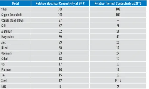
Conductor Characteristics
Relative electrical and thermal conductivities of common metal conductors are as follows:
table 2.1–relative electrical and thermal Conductivities of Common Conductor Materials
Metal relative electrical Conductivity at 20°C relative thermal Conductivity at 20°C
Silver 106 108
Copper (annealed) 100 100
Copper (hard drawn) 97 –
Gold 72 76 Aluminum 62 56 Magnesium 39 41 Zinc 29 29 Nickel 25 15 Cadmium 23 24 Cobalt 18 17 Iron 17 17 Platinum 16 18 Tin 15 17 Steel 12 13-17 Lead 8 9
2.1 strAnd tyPes
2.1.1 Concentric strand
A concentric stranded conductor consists of a central wire or core surrounded by one or more layers of helically laid wires. Each layer after the first has six more wires than the preceding layer. Except in compact stranding, each layer is usually applied in a direction opposite to that of the layer under it. If the core is a single wire and if it and all of the outer strands have the same diameter, the first layer will contain six wires; the second, twelve; the third, eighteen; etc.
Figure 2.1–Concentric Strand 2.1.2 bunch strand
The term bunch stranding is applied to a collection of strands twisted together in the same direction without regard to the geometric arrangement.
Figure 2.2–Bunch Strand 2.1.3 rope strand
A rope stranded conductor is a concentric stranded conductor each of whose component strands is itself stranded. A rope stranded conductor is described by giving the number of groups laid together to form the rope and the number of wires in each group.
Figure 2.3–Rope Strand 2.1.4 sector Conductor
A sector conductor is a stranded conductor whose cross-section is approximately the shape of a sector of a circle. A multiple conductor insulated cable with sector conductors has a smaller diameter than the corresponding cable with round conductors.
Figure 2.4–Sector Conductor 2.1.5 segmental Conductor
A segmental conductor is a round, stranded conductor composed of three or four sectors slightly insulated from one another. This construction has the advantage of lower AC resistance due to increased surface area and skin effect.
2.1.6 Annular Conductor
An annular conductor is a round, stranded conductor whose strands are laid around a suitable core. The core is usually made wholly or mostly of nonconducting material. This construction has the advantage of lower total AC resistance for a given cross-sectional area of conducting material due to the skin effect.
Figure 2.6–Annular Conductor 2.1.7 Compact strand
A compact stranded conductor is a round or sector conductor having all layers stranded in the same direction and rolled to a predetermined ideal shape. The finished conductor is smooth on the surface and contains practically no interstices or air spaces. This results in a smaller diameter.
Figure 2.7–Compact Conductor 2.1.8 Compressed strand
Compressed conductors are intermediate in size between standard concentric conductors and compact conductors. A comparison is shown below:
Compact Compressed Concentric
Solid
Figure 2.8–Comparative Sizes and Shapes of 1,000 kcmil Conductors
In a concentric stranded conductor, each individual wire is round and considerable space exists between wires. In a compressed conductor, the conductor has been put through a die that “squeezes out” some of the space between wires. In a compact conductor each wire is preformed into a trapezoidal shape before the wires are stranded together into a finished conductor. This results in even less space between wires. A compact conductor is, therefore, the smallest in diameter (except for a solid conductor, of course). Diameters for common conductor sizes are given in table 2.2.
table 2.2–diameters for Copper and Aluminum Conductors
Conductor size nominal diameters (in.)
(AWG) (kcmil) solid Class b
Compact CompressedClass b ConcentricClass b
8 16.51 0.1285 0.134 0.141 0.146 6 26.24 0.1620 0.169 0.178 0.184 4 41.74 0.2043 0.213 0.225 0.232 3 52.62 0.2294 0.238 0.252 0.260 2 66.36 0.2576 0.268 0.283 0.292 1 83.69 0.2893 0.299 0.322 0.332 1/0 105.6 0.3249 0.336 0.361 0.373 2/0 133.1 0.3648 0.376 0.406 0.419 3/0 167.8 0.4096 0.423 0.456 0.470 4/0 211.6 0.4600 0.475 0.512 0.528 – 250 0.5000 0.520 0.558 0.575 – 300 0.5477 0.570 0.611 0.630 – 350 0.5916 0.616 0.661 0.681 – 400 0.6325 0.659 0.706 0.728 – 450 0.6708 0.700 0.749 0.772 – 500 0.7071 0.736 0.789 0.813 – 550 0.7416 0.775 0.829 0.855 – 600 0.7746 0.813 0.866 0.893 – 650 0.8062 0.845 0.901 0.929 – 700 0.8367 0.877 0.935 0.964 – 750 0.8660 0.908 0.968 0.998 – 800 0.8944 0.938 1.000 1.031 – 900 0.9487 0.999 1.061 1.093 – 1,000 1.0000 1.060 1.117 1.152
Sources: ASTM B8 and B496 ICEA S-95-658 (NEMA WC-70)
2.2 CoAtinGs
There are three materials commonly used for coating a copper conductor: tin, silver and nickel.
Tin is the most common and is used for improved corrosion resistance, solderability and to reduce friction between strands in flexible cables. Silver-plated conductors are used in high-temperature environments (150°C–200°C). It is also used for high-frequency applications where silver’s high conductivity (better than copper) and the “skin effect” work together to reduce attenuation at high frequencies.
Nickel coatings are used for conductors that operate between 200°C and 450°C. At these high temperatures, copper oxidizes rapidly if not nickel plated. One drawback of nickel is its poor solderability and higher electrical resistance.
2.3 tensiLe strenGth oF CoPPer Wire
table 2.3–tensile strength of Copper Wire
size soft or Annealed Medium hard drawn hard drawn
(AWG) Max. breaking Load (lb.) Min. breaking Load (lb.) Min. breaking Load (lb.)
4/0 6,000 6,970 8,140 3/0 4,750 5,660 6,720 2/0 3,765 4,600 5,530 1/0 2,985 3,730 4,520 1 2,435 3,020 3,690 2 1,930 2,450 3,010 3 1,535 1,990 2,440 4 1,215 1,580 1,970 6 765 1,010 1,280 8 480 645 825 10 315 410 530 12 200 262 335 14 125 167 215 16 78.5 106 135 18 49.5 67.6 85.5 20 31.0 43.2 54.2 22 19.4 27.3 34.1 24 12.7 17.5 21.7 26 7.94 11.1 13.7 28 4.99 7.02 8.64 30 3.14 4.48 5.47 32 2.01 2.90 3.53 34 1.25 1.82 2.20 36 0.79 1.16 1.40
2.4 CoPPer strAnd ProPerties
2.4.1 strand Classes table 2.4–strand Classes
AstM
standard Construction Class Application
B8 Concentric lay AA For bare conductors – usually used in overhead lines.
A For bare conductors where greater flexibility than is afforded by Class AA is required.
B For conductors insulated with various materials such as EP, XLP, PVC, etc. This is the most common class.
C For conductors where greater flexibility is required than is provided by Class B.
D N/A
B173 Rope lay with concentric
stranded members G Conductor constructions having a range of areas from 5,000,000 circular mils and employing 61 stranded members of 19 wires each down to No. 14 AWG containing seven stranded members stranded members of seven wires each. Typical uses are for portable (flexible) conductors and similar applications.
H Conductor constructions having a range of areas from 5,000,000 circular mils and employing 91 stranded members of 19 wires each down to No. 9 AWG containing 19 stranded members of seven wires each. Typical uses are for rubber-jacketed cords and conductors where flexibility is required, such as for use on take-up reels, over sheaves and apparatus conductors.
AstM
standard Construction Class Conductor size individual Wire size Application (kcmil/AWG) diameter (in.) (AWG)
B172 Rope lay with bunch stranded members
I Up to 2,000 0.0201 24 Typical use is for special apparatus cable.
K Up to 2,000 0.0100 30 Typical use is for portable cord. M Up to 1,000 0.0063 34 Typical use is for welding cable. B174 Bunch stranded I 7, 8, 9, 10 0.0201 24 Rubber-covered conductors.
J 10, 12, 14, 16, 18, 20 0.0126 28 Fixture wire.
K 10, 12, 14, 16, 18, 20 0.0100 30 Fixture wire, flexible cord and portable cord. L 10, 12, 14, 16, 18, 20 0.0080 32 Fixture wire and portable cord with greater
flexibility than Class K. M 14, 16, 18, 20 0.0063 34 Heater cord and light portable cord. O 16, 18, 20 0.0050 36 Heater cord with greater flexibility than
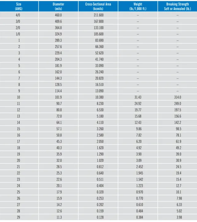
2.4.2 solid Copper
table 2.5–standard nominal diameters and Cross-sectional Areas of solid Copper Wire size
(AWG) diameter(mils) Cross-sectional Area(kcmils) (lb./1,000 ft.)Weight soft or Annealed (lb.)breaking strength
4/0 460.0 211.600 – – 3/0 409.6 167.800 – – 2/0 364.8 133.100 – – 1/0 324.9 105.600 – – 1 289.3 83.690 – – 2 257.6 66.360 – – 3 229.4 52.620 – – 4 204.3 41.740 – – 5 181.9 33.090 – – 6 162.0 26.240 – – 7 144.3 20.820 – – 8 128.5 16.510 – – 9 114.4 13.090 – – 10 101.9 10.380 31.43 314.0 11 90.7 8.230 24.92 249.0 12 80.8 6.530 19.77 197.5 13 72.0 5.180 15.68 156.6 14 64.1 4.110 12.43 142.2 15 57.1 3.260 9.86 98.5 16 50.8 2.580 7.82 78.1 17 45.3 2.050 6.20 61.9 18 40.3 1.620 4.92 49.2 19 35.9 1.290 3.90 39.0 20 32.0 1.020 3.09 30.9 21 28.5 0.812 2.452 24.5 22 25.3 0.640 1.945 19.4 23 22.6 0.511 1.542 15.4 24 20.1 0.404 1.223 12.7 25 17.9 0.320 0.970 10.1 26 15.9 0.253 0.770 7.98 27 14.2 0.202 0.610 6.33 28 12.6 0.159 0.484 5.02 29 11.3 0.128 0.384 3.98
table 2.5–standard nominal diameters and Cross-sectional Areas of solid Copper Wire (Continued) size
(AWG) diameter(mils) Cross-sectional Area(kcmils) (lb./1,000 ft.)Weight soft or Annealed (lb.)breaking strength
30 10.0 0.100 0.303 3.16 31 8.9 0.0792 0.241 2.50 32 8.0 0.0640 0.191 1.99 33 7.1 0.0504 0.152 1.58 34 6.3 0.0397 0.120 1.25 35 5.6 0.0314 0.095 0.990 36 5.0 0.0250 0.076 0.785 37 4.5 0.0202 0.060 0.623 38 4.0 0.0160 0.048 0.494 39 3.5 0.0122 – – 40 3.1 0.00961 – – 41 2.8 0.00784 – – 42 2.5 0.00625 – – 43 2.2 0.00484 – – 44 2.0 0.00400 – – 45 1.76 0.00310 – – 46 1.57 0.00246 – –
Source: ASTM B258, Specification for Standard Nominal Diameters and Cross-Sectional Areas of AWG Sizes of Solid Round Wires Used as Electrical Conductors
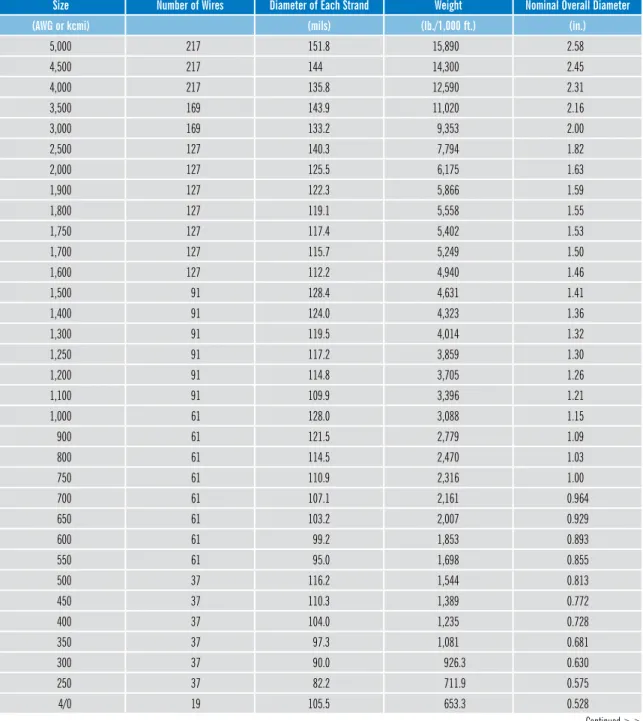
2.4.3 Class b, C and d Copper strand
table 2.6–Class b Concentric-Lay-stranded Copper Conductors
size number of Wires diameter of each strand Weight nominal overall diameter
(AWG or kcmi) (mils) (lb./1,000 ft.) (in.)
5,000 217 151.8 15,890 2.58 4,500 217 144 14,300 2.45 4,000 217 135.8 12,590 2.31 3,500 169 143.9 11,020 2.16 3,000 169 133.2 9,353 2.00 2,500 127 140.3 7,794 1.82 2,000 127 125.5 6,175 1.63 1,900 127 122.3 5,866 1.59 1,800 127 119.1 5,558 1.55 1,750 127 117.4 5,402 1.53 1,700 127 115.7 5,249 1.50 1,600 127 112.2 4,940 1.46 1,500 91 128.4 4,631 1.41 1,400 91 124.0 4,323 1.36 1,300 91 119.5 4,014 1.32 1,250 91 117.2 3,859 1.30 1,200 91 114.8 3,705 1.26 1,100 91 109.9 3,396 1.21 1,000 61 128.0 3,088 1.15 900 61 121.5 2,779 1.09 800 61 114.5 2,470 1.03 750 61 110.9 2,316 1.00 700 61 107.1 2,161 0.964 650 61 103.2 2,007 0.929 600 61 99.2 1,853 0.893 550 61 95.0 1,698 0.855 500 37 116.2 1,544 0.813 450 37 110.3 1,389 0.772 400 37 104.0 1,235 0.728 350 37 97.3 1,081 0.681 300 37 90.0 926.3 0.630 250 37 82.2 711.9 0.575 4/0 19 105.5 653.3 0.528 Continued >>
table 2.6–Class b Concentric-Lay-stranded Copper Conductors (Continued)
size number of Wires diameter of each strand Weight nominal overall diameter
(AWG or kcmi) (mils) (lb./1,000 ft.) (in.)
3/0 19 94.0 518.1 0.470 2/0 19 83.7 410.9 0.419 1/0 19 74.5 325.8 0.373 1 19 66.4 258.4 0.332 2 7 97.4 204.9 0.292 3 7 86.7 162.5 0.260 4 7 77.2 128.9 0.232 5 7 68.8 102.2 0.206 6 7 61.2 81.05 0.184 7 7 54.5 64.28 0.164 8 7 48.6 50.97 0.146 9 7 43.2 40.42 0.130 10 7 38.5 32.06 0.116 12 7 30.5 20.16 0.0915 14 7 24.2 12.68 0.0726 16 7 19.2 7.974 0.0576 18 7 15.2 5.015 0.0456 20 7 12.1 3.154 0.0363
table 2.7–Copper strand diameters
Conductor size stranding
(AWG) (kcmil) Class b Compact (in.) Class b Compressed (in.) Class b Concentric (in.) Class C Concentric (in.) Class d Concentric (in.)
14 4.11 – 0.0704 0.0727 0.0735 0.0735 13 5.18 – 0.0792 0.0816 0.0825 0.0826 12 6.53 – 0.0888 0.0915 0.0925 0.0931 11 8.23 – 0.0998 0.103 0.104 0.104 10 10.39 – 0.113 0.116 0.117 0.117 9 13.09 – 0.126 0.130 0.131 0.132 8 16.51 0.134 0.141 0.146 0.148 0.148 7 20.82 – 0.158 0.164 0.166 0.166 6 26.24 0.169 0.178 0.184 0.186 0.186 5 33.09 – 0.200 0.206 0.208 0.209 4 41.74 0.213 0.225 0.232 0.234 0.235 3 52.62 0.238 0.252 0.260 0.263 0.264 2 66.36 0.268 0.283 0.292 0.296 0.297 1 83.69 0.299 0.322 0.332 0.333 0.333 1/0 105.6 0.336 0.362 0.372 0.374 0.374 2/0 133.1 0.376 0.406 0.418 0.420 0.420 3/0 167.8 0.423 0.456 0.470 0.471 0.472 4/0 211.6 0.475 0.512 0.528 0.529 0.530 – 250 0.520 0.558 0.575 0.576 0.576 – 300 0.570 0.611 0.630 0.631 0.631 – 350 0.616 0.661 0.681 0.681 0.682 – 400 0.659 0.706 0.728 0.729 0.729 – 450 0.700 0.749 0.772 0.773 0.773 – 500 0.736 0.789 0.813 0.814 0.815 – 550 0.775 0.829 0.855 0.855 0.855 – 600 0.813 0.866 0.893 0.893 0.893 – 650 0.845 0.901 0.929 0.930 0.930 – 700 0.877 0.935 0.964 0.965 0.965 – 750 0.908 0.968 0.999 0.999 0.998 – 800 0.938 1.000 1.030 1.032 1.032 – 900 0.999 1.061 1.094 1.093 1.095 – 1,000 1.060 1.117 1.152 1.153 1.153 – 1,100 – 1.173 1.209 1.210 1.211 Continued >>
table 2.7–Copper strand diameters (Continued)
Conductor size stranding
(AWG) (kcmil) Class b Compact (in.) Class b Compressed (in.) Class b Concentric (in.) Class C Concentric (in.) Class d Concentric (in.)
– 1,200 – 1.225 1.263 1.264 1.264 – 1,250 – 1.251 1.289 1.290 1.290 – 1,300 – 1.275 1.314 1.316 1.316 – 1,400 – 1.323 1.365 1.365 1.365 – 1,500 – 1.370 1.412 1.413 1.413 – 1,600 – 1.415 1.459 1.460 1.460 – 1,700 – 1.459 1.504 1.504 1.504 – 1,750 – 1.480 1.526 1.527 1.527 – 1,800 – 1.502 1.548 1.548 1.549 – 1,900 – 1.542 1.590 1.590 1.591 – 2,000 – 1.583 1.632 1.632 1.632 – 2,500 – 1.769 1.824 1.824 1.824 – 3,000 – 1.938 1.998 1.998 1.998 2.4.4 Class h Copper
table 2.8–Class h rope-Lay-stranded Copper Conductors
size (AWG or kcmil) number of strands Construction nominal diameter of each strand (in.) nominal o.d. (in.) nominal Weight (lb./1,000 ft.)
8 133 19x7 0.0111 0.167 52 7 133 19x7 0.0125 0.188 65 6 133 19x7 0.0140 0.210 82 5 133 19x7 0.0158 0.237 105 4 133 19x7 0.0177 0.266 132 3 133 19x7 0.0199 0.299 167 2 133 19x7 0.0223 0.335 208 2 259 37x7 0.0160 0.336 210 1 259 37x7 0.0180 0.378 266 1/0 259 37x7 0.0202 0.424 334 2/0 259 37x7 0.0227 0.477 422 3/0 259 37x7 0.0255 0.536 533 3/0 427 61x7 0.0198 0.535 532 4/0 259 37x7 0.0286 0.601 670
table 2.8–Class h rope-Lay-stranded Copper Conductors (Continued)
size (AWG or kcmil) number of strands Construction nominal diameter of each strand (in.) nominal o.d. (in.) nominal Weight (lb./1,000 ft.)
250 427 61x7 0.0242 0.653 795 300 427 61x7 0.0265 0.716 953 350 427 61x7 0.0286 0.772 1,110 400 427 61x7 0.0306 0.826 1,270 450 427 61x7 0.0325 0.878 1,435 500 427 61x7 0.0342 0.923 1,590 550 703 37x19 0.0280 0.980 1,770 600 703 37x19 0.0292 1.022 1,920 650 703 37x19 0.0304 1.064 2,085 700 703 37x19 0.0316 1.106 2,255 750 703 37x19 0.0327 1.145 2,410 800 703 37x19 0.0337 1.180 2,560 900 703 37x19 0.0358 1.253 2,895 1,000 703 37x19 0.0377 1.320 3,205 1,100 703 37x19 0.0396 1.386 3,535 1,200 703 37x19 0.0413 1.446 3,845 1,250 703 37x19 0.0422 1.477 4,015 1,300 703 37x19 0.0430 1.505 4,170 1,400 703 37x19 0.0446 1.561 4,485 1,500 703 37x19 0.0462 1.617 4,815 1,600 1,159 61x19 0.0372 1.674 5,145 1,700 1,159 61x19 0.0383 1.724 5,455 1,750 1,159 61x19 0.0389 1.751 5,625 1,800 1,159 61x19 0.0394 1.773 5,770 1,900 1,159 61x19 0.0405 1.823 6,100 2,000 1,159 61x19 0.0415 1.868 6,400
2.4.5 Class i Copper
table 2.9–Class i (24 AWG strands) rope-Lay-stranded Copper Conductors
size (AWG or kcmil) Construction nominal number of strands nominal 0.d. (in.) nominal Weight (lb./1,000 ft.)
10 1x26 26 0.125 32.5 9 1x33 33 0.138 41 8 1x41 41 0.156 51 7 1x52 52 0.185 65 6 7x9 63 0.207 80 5 7x12 84 0.235 105 4 7x15 105 0.263 134 3 7x19 133 0.291 169 2 7x23 161 0.319 205 1 7x30 210 0.367 267 1/0 19x14 266 0.441 342 2/0 19x18 342 0.500 439 3/0 19x22 418 0.549 537 4/0 19x28 532 0.613 683 250 7x7x13 637 0.682 825 300 7x7x15 735 0.737 955 350 7x7x18 882 0.800 1,145 400 7x7x20 980 0.831 1,270 450 7x7x23 1,127 0.894 1,460 500 7x7x25 1,225 0.941 1,590 550 7x7x28 1,372 0.980 1,780 600 7x7x30 1,470 1.027 1,905 650 19x7x12 1,596 1.152 2,090 700 19x7x13 1,729 1.194 2,260 750 19x7x14 1,862 1.235 2,435 800 19x7x15 1,995 1.290 2,610 900 19x7x17 2,261 1.372 2,965 1,000 19x7x19 2,527 1.427 3,305 1,100 19x7x21 2,793 1.495 3,655 1,200 19x7x22 2,926 1.537 3,830 1,250 19x7x23 3,059 1.564 4,000 1,300 19x7x24 3,192 1.605 4,175 1,400 19x7x26 3,458 1.674 4,560 1,500 19x7x28 3,724 1.715 4,875 1,600 19x7x30 3,990 1.797 5,220 1,700 19x7x32 4,256 1.852 5,570 1,750 19x7x33 4.389 1.880 5,745
2.4.6 Class K Copper
table 2.10–Class K (30 AWG strands) rope-Lay-stranded Copper Conductors
size rope-Lay with bunch stranding bunch stranding Weight
(AWG or kcmil) nominal number of strands Constructionstrand nominal number of strands Approx. o.d. (in.) (lb./1,000 ft.)
1,000 10,101 37x7x39 10,101 1.419 3,270 900 9,065 37x7x35 9,065 1.323 2,935 800 7,980 19x7x60 7,980 1.305 2,585 750 7,581 19x7x57 7,581 1.276 2,455 700 6,916 19x7x52 6,916 1.207 2,240 650 6,517 19x7x49 6,517 1.166 2,110 600 5,985 19x7x45 5,985 1.125 1,940 550 5,453 19x7x41 5,453 1.056 1,765 500 5,054 19x7x38 5,054 0.988 1,635 450 4,522 19x7x34 4,522 0.933 1,465 400 3,990 1x7x30 3,990 0.878 1,290 350 3,458 19x7x26 3,458 0.809 1,120 300 2,989 7x7x61 2,989 0.768 960 250 2,499 7x7x51 2,499 0.682 802 4/0 2,107 7x7x43 2,107 0.627 676 3/0 1,666 7x7x34 1,666 0.533 535 2/0 1,323 7x7x27 1,323 0.470 425 1/0 1,064 19x56 1,064 0.451 338 1 836 19x44 836 0.397 266 2 665 19x35 665 0.338 211 3 532 19x28 532 0.304 169 4 420 7x60 420 0.272 132 5 336 7x48 336 0.235 106 6 266 7x38 266 0.202 84 7 210 7x30 210 0.179 66 8 168 7x24 168 0.157 53 9 133 7x19 133 0.146 42 10 – – 104 0.126 32.5 12 – – 65 0.101 20.3 14 – – 41 0.078 12.8 16 – – 26 0.060 8.0 18 – – 16 0.048 5.0 20 – – 10 0.038 3.2
Sources: ASTM B172 Specification for Rope-Lay-Stranded Copper Conductors Having Bunch-Stranded Members and ICEA S-75-381 (NEMA WC58) Appendix K
2.4.7 Class M Copper
table 2.11–Class M (34 AWG strands) rope-Lay-stranded Copper Conductors
size rope-Lay with bunch stranding bunch stranding Weight
(AWG or kcmil) nominal number of strands Constructionstrand nominal number of strands Approx. o.d. (in.) (lb./1,000 ft.)
1,000 25,193 61x7x59 25,193 1.404 3,240 900 22,631 61x7x53 22,631 1.331 2,910 800 20,069 61x7x47 20,069 1.256 2,580 750 18,788 61x7x44 18,788 1.207 2,415 700 17,507 61x7x41 17,507 1.183 2,250 650 16,226 61x7x38 16,226 1.133 2,085 600 14,945 61x7x35 14,945 1.084 1,920 550 13,664 61x7x32 13,664 1.035 1,755 500 12,691 37x7x49 12,691 0.997 1,630 450 11,396 37x7x44 11,396 0.940 1,465 400 10,101 37x7x39 10,101 0.901 1,300 350 8,806 37x7x34 8,806 0.825 1,130 300 7,581 19x7x57 7,581 0.768 975 250 6,384 19x7x48 6,384 0.713 821 4/0 5,320 19x7x40 5,320 0.645 684 3/0 4,256 19x7x32 4,256 0.576 547 2/0 3,325 19x7x25 3,325 0.508 427 1/0 2,646 7x7x54 2,646 0.423 337 1 2,107 7x7x43 2,107 0.376 268 2 1,666 7x7x34 1,666 0.337 212 3 1,323 7x7x27 1,323 0.305 169 4 1,064 19x56 1,064 0.269 134 5 836 19x44 836 0.240 105 6 665 19x35 665 0.215 84 7 532 19x28 532 0.196 67 8 420 7x60 420 0.162 53 9 336 7x48 336 0.146 42 10 259 7x37 259 0.126 32.5 12 168 7x24 168 0.101 21.0 14 – – 104 0.078 12.8 16 – – 65 0.060 8.0
2.5 ALuMinuM strAnd ProPerties
2.5.1 solid Aluminum
table 2.12–Aluminum 1350 solid round Wire
size (AWG or kcmil) diameter (mils) Cross-sectional Area (kcmils) Weight (lb./1,000 ft.)
4/0 460.0 211.600 194.40 3/0 409.6 167.800 154.20 2/0 364.8 133.100 122.30 1/0 324.9 105.600 97.00 1 289.3 83.690 76.91 2 257.6 66.360 60.98 3 229.4 52.620 48.36 4 204.3 41.740 38.35 5 181.9 33.090 30.40 6 162.0 26.240 24.12 7 144.3 20.820 19.13 8 128.5 16.510 15.17 9 114.4 13.090 12.03 10 101.9 10.380 9.542 11 90.7 8.230 7.559 12 80.8 6.530 5.999 13 72.0 5.180 4.764 14 64.1 4.110 3.776 15 57.1 3.260 2.996 16 50.8 2.580 2.371 17 45.3 2.050 1.886 18 40.3 1.620 1.492 19 35.9 1.290 1.184 20 32.0 1.020 0.9410 21 28.5 0.812 0.7464 22 25.3 0.640 0.5882 23 22.6 0.511 0.4693 24 20.1 0.404 0.3713 25 17.9 0.320 0.2944 26 15.9 0.253 0.2323 27 14.2 0.202 0.1853 28 12.6 0.159 0.1459 29 11.3 0.128 0.1173 30 10.0 0.100 0.09189
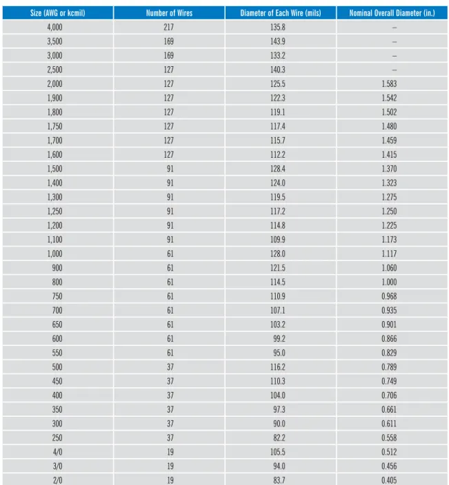
2.5.2 Class b Aluminum
table 2.13–Class b Concentric-Lay-stranded Compressed, reverse-Lay Aluminum 1350 Conductors
size (AWG or kcmil) number of Wires diameter of each Wire (mils) nominal overall diameter (in.)
4,000 217 135.8 – 3,500 169 143.9 – 3,000 169 133.2 – 2,500 127 140.3 – 2,000 127 125.5 1.583 1,900 127 122.3 1.542 1,800 127 119.1 1.502 1,750 127 117.4 1.480 1,700 127 115.7 1.459 1,600 127 112.2 1.415 1,500 91 128.4 1.370 1,400 91 124.0 1.323 1,300 91 119.5 1.275 1,250 91 117.2 1.250 1,200 91 114.8 1.225 1,100 91 109.9 1.173 1,000 61 128.0 1.117 900 61 121.5 1.060 800 61 114.5 1.000 750 61 110.9 0.968 700 61 107.1 0.935 650 61 103.2 0.901 600 61 99.2 0.866 550 61 95.0 0.829 500 37 116.2 0.789 450 37 110.3 0.749 400 37 104.0 0.706 350 37 97.3 0.661 300 37 90.0 0.611 250 37 82.2 0.558 4/0 19 105.5 0.512 3/0 19 94.0 0.456
table 2.13–Class b Concentric-Lay-stranded Compressed, reverse-Lay Aluminum 1350 Conductors (Continued)
size (AWG or kcmil) number of Wires diameter of each Wire (mils) nominal overall diameter (in.)
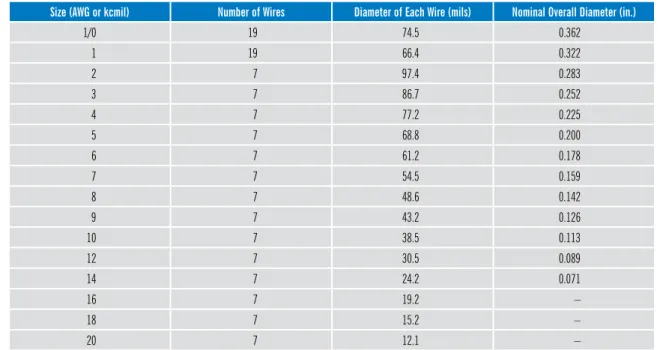
1/0 19 74.5 0.362 1 19 66.4 0.322 2 7 97.4 0.283 3 7 86.7 0.252 4 7 77.2 0.225 5 7 68.8 0.200 6 7 61.2 0.178 7 7 54.5 0.159 8 7 48.6 0.142 9 7 43.2 0.126 10 7 38.5 0.113 12 7 30.5 0.089 14 7 24.2 0.071 16 7 19.2 – 18 7 15.2 – 20 7 12.1 –
Source: ASTM B231 Concentric-Lay-Stranded Aluminum 1350 Conductors
2.5.3 ACsr
table 2.14–Concentric-Lay-stranded Aluminum Conductors, Coated-steel reinforced (ACsr)
size stranding Weight
(AWG or kcmil) Aluminum number/diameter (in.) steel number/diameter (in.) (lb./1,000 ft.)
2,156 84/0.1602 19/0.0961 2,511 1,780 84/0.1456 19/0.0874 2,074 1,590 54/0.1716 19/0.1030 2,044 1,590 45/0.1880 7/0.1253 1,792 1,431 54/0.1628 19/0.0977 1,840 1,431 45/0.1783 7/0.1189 1,613 1,272 54/0.1535 19/0.0921 1,635 1,272 45/0.1681 7/0.1121 1,434 1,113 54/0.1436 19/0.0862 1,431 1,113 45/0.1573 7/0.1049 1,255 954.0 54/0.1329 7/0.1329 1,229 954.0 45/0.1456 7/0.0971 1,075 Continued >>
table 2.14–Concentric-Lay-stranded Aluminum Conductors, Coated-steel reinforced (ACsr) (Continued)
size stranding Weight
(AWG or kcmil) Aluminum number/diameter (in.) steel number/diameter (in.) (lb./1,000 ft.)
795.0 45/0.1329 7/0.0886 896 795.0 26/0.1749 7/0.1360 1,094 795.0 24/0.1820 7/0.1213 1,023 636.0 26/0.1564 7/0.1216 875 636.0 24/0.1628 7/0.1085 819 636.0 18/0.1880 1/0.1880 690 556.5 26/0.1463 7/0.1138 766 556.5 24/0.1523 7/0.1015 717 556.5 18/0.1758 1/0.1758 604 477.0 30/0.1261 7/0.1261 747 477.0 26/0.1354 7/0.1053 657 477.0 24/0.1410 7/0.0940 615 477.0 18/0.1628 1/0.1628 518 397.5 26/0.1236 7/0.0961 547 397.5 24/0.1287 7/0.0858 512 397.5 18/0.1486 1/0.1486 432 336.4 30/0.1059 7/0.1059 527 336.4 26/0.1137 7/0.0884 463 336.4 18/0.1367 1/0.1367 365 266.8 26/0.1013 7/0.0788 367 266.8 18/0.1217 1/0.1217 290 4/0 6/0.1878 1/0.1878 291.1 211.3 12/0.1327 7/0.1327 527.5 203.2 16/0.1127 19/0.0977 676.8 190.8 12/0.1261 7/0.1261 476.3 176.9 12/0.1214 7/0.1214 441.4 3/0 6/0.1672 1/0.1672 230.8 159.0 12/0.1151 7/0.1151 396.8 134.6 12/0.1059 7/0.1059 336.0 2/0 6/0.1489 1/0.1489 183.1 110.8 12/0.0961 7/0.0961 276.6 1/0 6/0.1327 1/0.1327 145.2 101.8 12/0.0921 7/0.0921 254.1 80.0 8/0.1000 1/0.1670 149.0 2 7/0.0974 1/0.1299 106.7 2 6/0.1052 1/0.1052 91.3
2.6 AdditionAL ConduCtor ProPerties
2.6.1 stranding, diameter, Area and dC resistance (32 through 4/0 AWG) table 2.15–stranding, diameter, Area and dC resistance
size stranding Conductor diameter Conductor Area Copper dC resistance at 20°C
(AWG) (no./AWG) (in.) (mm) (cmils) (mm2) (ohms/1,000 ft.) (ohms/km)
30 Solid 0.010 0.254 100.0 0.051 106.6 349.8 7/38 0.012 0.305 112.0 0.057 96.2 315.6 28 Solid 0.013 0.320 159.0 0.081 70.8 232.3 7/36 0.015 0.381 175.0 0.089 67.5 221.5 19/40 0.016 0.406 182.6 0.093 58.9 193.3 26 Solid 0.016 0.406 253.0 0.128 44.5 146.0 7/34 0.019 0.483 278.0 0.141 42.5 139.4 19/38 0.021 0.533 304.0 0.154 38.9 127.6 24 Solid 0.020 0.511 404.0 0.205 27.2 89.2 7/32 0.024 0.610 448.0 0.227 25.7 84.3 10/34 0.023 0.584 397.0 0.201 28.8 94.5 19/36 0.025 0.635 475.0 0.241 24.9 81.7 22 Solid 0.025 0.635 475.0 0.326 16.7 54.8 7/30 0.031 0.787 700.0 0.355 16.6 54.5 16/34 0.030 0.762 635.0 0.322 18.0 59.1 19/34 0.032 0.813 754.0 0.382 15.5 50.9 20 Solid 0.032 0.813 1,020 0.517 10.5 34.5 7/28 0.038 0.965 1,113 0.564 10.3 33.8 10/30 0.036 0.914 1,000 0.507 11.4 37.4 19/32 0.040 1.02 1,197 0.607 9.48 31.1 26/34 0.037 0.940 1,032 0.523 11.3 37.1 18 Solid 0.040 1.02 1,620 0.821 6.77 22.2 7/26 0.048 1.22 1,771 0.897 6.45 21.2 16/30 0.046 1.17 1,600 0.811 6.15 23.5 19/30 0.050 1.27 1,900 0.963 6.10 20.0 41/34 0.047 1.19 1,627 0.824 7.08 23.2 16 Solid 0.051 1.29 2,580 1.31 4.47 14.7 7/24 0.058 1.47 2,828 1.43 4.04 13.3 19/29 0.057 1.45 2,426 1.23 4.82 15.8 26/30 0.050 1.52 2,600 1.32 4.39 14.4 65/34 0.060 1.52 2,580 1.32 4.47 14.7 Continued >>
table 2.15–stranding, diameter, Area and dC resistance (Continued)
size stranding Conductor diameter Conductor Area Copper dC resistance at 20°C
(AWG) (no./AWG) (in.) (mm) (cmils) (mm2) (ohms/1,000 ft.) (ohms/km)
14 Solid 0.064 1.63 4,110 2.08 2.68 8.79 19/27 0.071 1.80 3,838 1.94 3.05 10.0 41/30 0.077 1.96 4,100 2.08 2.81 9.22 12 Solid 0.081 2.05 6,530 3.31 1.65 5.41 19/25 0.090 2.29 6,080 3.08 1.87 6.14 65/30 0.091 2.31 6,500 3.29 1.82 5.97 10 Solid 0.102 2.59 10,380 5.26 1.11 3.64 37/36 0.112 2.84 9,361 4.74 1.38 4.53 105/30 0.130 3.30 10,500 5.32 1.10 3.61 8 Solid 0.129 3.28 16,500 8.36 0.718 2.36 133/29 0.166 4.22 17,024 8.63 0.710 2.33 168/30 0.174 4.42 16,800 8.51 0.700 2.30 6 Solid 0.162 4.12 26,240 13.3 0.440 1.44 133/27 0.210 5.33 26,866 13.6 0.430 1.41 266/30 0.204 5.18 26,600 13.5 0.440 1.44 4 Solid 0.204 5.18 41,740 21.1 0.275 0.902 133/25 0.257 6.53 42,560 21.6 0.290 0.951 420/30 0.257 6.53 42,000 21.3 0.280 0.919 2 Solid 0.258 6.54 66,360 33.6 0.172 0.564 665/30 0.338 8.59 66,500 33.7 0.180 0.591 1 Solid 0.289 7.34 83,690 42.4 0.142 0.466 817/30 0.328 8.33 81,700 41.4 0.140 0.459 1/0 Solid 0.325 8.26 105,600 53.5 0.111 0.364 1,045/30 0.410 10.4 104,500 53.0 0.120 0.394 2/0 Solid 0.365 9.27 133,100 67.4 0.088 0.289 1,330/30 0.496 12.6 133,000 67.4 0.099 0.325 3/0 Solid 0.410 10.4 167,800 85.0 0.070 0.230 1,661/30 0.464 11.8 166,100 84.2 0.068 0.223 4/0 Solid 0.460 11.7 211,600 107 0.055 0.180 2,104/30 0.608 15.4 210,400 107 0.060 0.197
2.6.2 stranding, diameter, Area, dC resistance and Weight (20 AWG through 2,000 kcmil) table 2.16–Copper Conductor stranding, diameter, Area, Weight and dC resistance
nominal
Area size number/diameter of individual Wires diameteroverall nominal Weight dC resistance at 20°C (68°F)
(mm2) (cmils) (AWG) (in.) (mm) (in.) (mm) (lb./
1,000 ft.) (kg/km) 1,000 ft.)(ohms/ (ohms/km) 0.50 987 – 1/0.032 1/0.613 0.032 0.81 3.100 4.613 10.13 32.33 – 1,020 20 7/0.0121 7/0.307 0.036 0.91 3.157 4.098 10.22 33.77 0.75 1,480 – 1/0.036 1/0.991 0.039 0.99 4.603 6.851 6.820 22.37 – 1,620 18 1/0.403 1/1.02 0.040 1.02 4.917 7.316 6.387 20.95 – 1,620 18 7/0.0152 7/0.386 0.046 1.16 4.980 7.410 6.523 21.40 1.0 1,970 – 1/0.045 1/1.14 0.045 1.14 6.130 9.122 5.127 16.80 1.0 1,970 – 7/0.017 7/0.432 0.051 1.30 6.293 9.266 5.213 17.11 – 2,580 16 1/0.0508 1/1.29 0.061 1.29 7.810 11.63 4.020 13.19 – 2,580 16 7/0.0192 7/0.488 0.058 1.46 7.877 11.82 4.087 13.41 1.5 2,960 – 1/0.055 1/1.40 0.055 1.40 9.157 13.63 3.430 11.25 1.5 2,960 – 7/0.021 7/0.533 0.063 1.60 8.837 14.14 3.417 11.21 – 4,110 14 1/0.641 1/1.63 0.064 1.63 12.44 18.51 2.524 8.281 – 4,110 14 7/0.0242 7/0.615 0.073 1.84 12.62 18.78 2.573 8.442 2.5 4,930 – 1/0.071 1/1.80 0.071 1.80 15.26 22.71 2.057 6.750 2.5 4,930 – 7/0.027 7/0.686 0.081 2.06 15.71 23.38 2.067 6.782 – 6,530 12 1/0.0808 1/2.05 0.081 2.05 19.76 29.41 1.589 5.212 – 6,530 12 7/0.0305 7/0.755 0.092 2.32 20.05 29.84 1.620 5.315 4 7,890 – 1/0.089 1/2.26 0.089 2.26 23.98 35.68 1.309 4.296 4 7,890 – 7/0.034 7/0.864 0.102 2.59 24.91 37.08 1.304 4.277 – 10,380 10 1/0.1019 1/2.59 0.102 2.59 31.43 46.77 0.999 3.277 – 10,380 10 7/0.0385 7/0.978 0.116 2.93 31.94 47.54 1.017 3.335 6 11,800 – 1/0.109 1/2.77 0.109 2.77 35.97 53.52 0.8730 2.864 6 11,800 – 7/0.042 7/0.107 0.126 3.21 38.00 56.55 0.8543 2.803 – 13,090 9 1/0.1144 7/2.91 0.1144 2.91 39.60 58.93 0.7923 2.600 – 13,090 9 7/0.0432 7/1.10 0.130 3.30 40.23 59.86 0.8073 2.649 – 16,510 8 1/0.1285 1/3.26 0.128 3.26 50.17 74.36 0.6147 2.061 – 16,510 8 7/0.0486 7/1.23 0.146 3.70 50.90 75.75 0.6380 2.093 10 19,700 – 1/0.141 1/3.58 0.141 3.58 60.17 89.54 0.5217 1.711 10 19,700 – 7/0.054 7/1.37 0.162 4.12 62.83 93.51 0.5167 1.695 – 20,820 7 1/0.1443 1/3.67 0.144 3.67 63.03 93.80 0.4980 1.634 – 20,820 7 7/0.0545 7/1.38 0.164 4.15 64.00 95.24 0.5073 1.664 Continued >>
table 2.16–Copper Conductor stranding, diameter, Area, Weight and dC resistance (Continued) nominal
Area size number/diameter of individual Wires diameteroverall nominal Weight dC resistance at 20°C (68°F) (mm2) (cmils) (AWG) (in.) (mm) (in.) (mm) 1,000 ft.)(lb./ (kg/km) 1,000 ft.)(ohms/ (ohms/km)
– 26,240 6 1/0.162 1/4.11 0.162 4.11 79.43 118.2 0.3950 1.296 – 26,240 6 7/0.0612 7/1.55 0.184 4.66 80.73 120.1 0.4023 1.320 16 31,600 – 7/0.068 7/1.73 0.204 5.18 99.67 148.3 0.3259 1.069 – 33,090 6 7/0.0688 7/1.75 0.206 5.24 102.0 151.8 0.3183 1.044 – 41,740 4 7/0.0772 7/1.96 0.232 5.88 128.4 191.1 0.2528 0.8295 25 49,300 – 7/0.065 7/2.16 0.255 6.48 155.7 231.7 0.2176 0.6843 – 52,620 3 7/0.0867 7/2.20 0.260 6.61 162.0 241.1 0.2005 0.6577 35 69,100 – 7/0.100 7/2.54 0.300 7.62 215.5 320.7 0.1507 0.4944 35 69,100 – 19/0.061 19/1.55 0.305 7.75 218.1 324.5 0.1495 0.4909 – 83,690 1 19/0.0664 19/1.63 0.332 8.43 258.4 384.5 0.1261 0.4139 50 98,700 – 19/0.073 19/1.85 0.365 9.27 312.3 464.8 0.1044 0.3424 – 105,400 1/0 19/0.0745 19/1.89 0.373 9.46 325.3 484.1 0.10020 0.3288 – 133,100 2/0 19/0.0837 19/2.13 0.419 10.6 410.7 611.1 0.07940 0.2605 70 138,000 – 19/0.086 19/2.18 0.430 10.9 433.3 645.0 0.07520 0.2467 – 167,800 3/0 19/0.094 19/2.39 0.470 11.9 517.7 770.4 0.06293 0.2065 – 167,800 3/0 37/0.0673 37/1.71 0.471 12.0 517.0 769.4 0.06310 0.2070 95 187,000 – 19/0.101 19/2.57 0.505 12.8 597.7 889.4 0.05453 0.1789 – 211,600 4/0 19/0.1055 19/2.68 0.528 13.4 652.3 970.8 0.04997 0.1639 120 237,000 – 37/0.0811 37/2.06 0.567 14.4 749.0 1,115 0.04357 0.1429 – 250,000 – 37/0.0822 37/2.09 0.575 14.6 771.3 1,148 0.04230 0.1388 150 300,000 – 37/0.090 37/2.29 0.630 16.0 924.7 1,376 0.03527 0.1157 – 350,000 – 37/0.0973 37/2.47 0.681 17.3 1,081 1,609 0.03018 0.09903 185 365,000 – 37/0.100 37/2.54 0.700 17.8 1,142 1,699 0.02857 0.09375 – 400,000 – 37/0.104 37/2.64 0.728 18.5 1,235 1,838 0.02642 0.06668 240 474,000 – 37/0.114 37/2.90 0.798 20.3 1,484 2,206 0.02199 0.07214 240 474,000 – 61/0.089 61/2.26 0.801 20.3 1,491 2,219 0.02189 0.07181 – 500,000 – 37/0.1162 37/2.95 0.813 20.7 1,608 2,294 0.02116 0.06943 – 500,000 – 61/0.0905 61/2.30 0.814 20.7 1,549 2,295 0.02117 0.06944 300 592,000 – 61/0.099 61/2.51 0.891 22.6 1,842 2,746 0.02102 0.05803 – 600,000 – 61/0.0992 61/2.52 0.893 22.7 1,853 2,757 0.01762 0.05780 – 700,000 – 61/0.1071 61/2.72 0.964 24.5 2,160 3,214 0.01511 0.04959
table 2.16–Copper Conductor stranding, diameter, Area, Weight and dC resistance (Continued) nominal
Area size number/diameter of individual Wires diameteroverall nominal Weight dC resistance at 20°C (68°F) (mm2) (cmils) (AWG) (in.) (mm) (in.) (mm) 1,000 ft.)(lb./ (kg/km) 1,000 ft.)(ohms/ (ohms/km)
– 750,000 – 91/0.0908 91/2.31 0.999 25.4 2,316 3,447 0.01410 0.04625 400 789,000 – 61/0.114 61/2.90 1.026 26.1 2,447 3,642 0.01334 0.04377 – 800,000 – 61/0.1145 61/2.91 1.031 26.2 2,468 3,673 0.01322 0.04338 – 800,000 – 91/0.0938 91/2.38 1.032 26.2 2,471 3,678 0.01321 0.04334 500 1,000,000 – 61/0.1280 61/3.25 1.152 29.3 3,085 4,590 0.01058 0.03472 – 1,000,000 – 91/0.1048 91/2.66 1.153 29.3 3,085 4,591 0.01058 0.03472 625 1,234,000 – 91/0.117 91/2.97 1.287 32.7 3,845 5,722 0.00849 0.02786 – 1,250,000 – 91/0.1172 91/2.98 1.289 32.7 3,858 5,742 0.008460 0.02776 – 1,250,000 – 127/0.0992 127/2.52 1.290 32.8 3,858 6,741 0.008463 0.02777 – 1,500,000 – 91/0.1284 91/3.26 1.412 35.9 4,631 6,892 0.007050 0.02313 – 1,500,000 – 127/0.1087 127/2.76 1.413 35.9 4,632 6,894 0.007183 0.02312 800 1,580,000 – 91/0.132 91/3.35 1.452 36.9 4,894 7,284 0.006670 0.02188 1,000 1,970,000 – 91/0.147 91/3.73 1.617 41.1 6,070 9,033 0.005380 0.01765 – 2,000,000 – 127/0.1255 127/3.19 1.632 41.5 6,175 9,189 0.005287 0.01735 – 2,000,000 – 169/0.1088 169/2.76 1.632 41.5 6,176 9,191 0.005287 0.01735
2.6.3 ieC stranding
table 2.17–typical ieC stranding
Cross section ordinary stranding (Class 2) Multi-Wire stranding stranding (Class 5)Fine Wire extra-Fine Wire stranding (Class 6)
(mm2) no./dia. (mm) no./dia. (mm) no./dia. (mm) no./dia. (mm)
0.05 – – – – – – 25/0.05 0.08 – – – – – – 41/0.05 0.14 – – – 18/0.10 18/0.1 36/0.07 72/0.05 0.25 – – 14/0.16 32/0.10 32/0.1 65/0.07 128/0.05 0.34 – 7/0.25 19/0.16 42/0.10 42/0.1 88/0.07 174/0.05 0.38 – 7/0.27 12/0.21 21/0.16 48/0.1 100/0.07 194/0.05 0.5 7/0.30 7/0.30 16/0.21 28/0.16 64/0.1 131/0.07 256/0.05 0.75 7/0.37 7/0.37 24/0.21 42/0.16 69/0.1 195/0.07 384/0.05 1.0 7/0.43 7/0.43 32/0.21 56/0.16 128/0.1 260/0.07 512/0.05 1.5 7/0.52 7/0.52 30/0.26 84/0.16 192/0.1 392/0.07 768/0.05 2.5 7/0.67 19/0.41 50/0.26 140/0.16 320/0.1 651/0.07 1,280/0.05 4 7/0.85 19/0.52 56/0.31 224/0.16 512/0.1 1,040/0.07 – 6 7/1.05 19/0.64 84/0.31 192/0.21 768/0.1 1,560/0.07 – 10 7/1.35 49/0.51 80/0.41 320/0.21 1,280/0.1 2,600/0.07 – 16 7/1.70 49/0.65 128/0.41 512/0.21 2,048/0.1 – – 25 7/2.13 84/0.62 200/0.41 800/0.21 3,200/0.1 – 35 7/2.52 133/0.58 280/0.41 1,120/0.21 – – – 50 19/1.83 133/0.69 400/0.41 705/0.31 – – – 70 19/2.17 189/0.69 356/0.51 990/0.31 – – – 95 19/2.52 259/0.69 485/0.51 1,340/0.31 – – – 120 37/2.03 336/0.67 614/0.51 1,690/0.31 – – – 150 37/2.27 392/0.69 765/0.51 2,123/0.31 – – – 185 37/2.52 494/0.69 944/0.51 1,470/0.41 – – – 240 61/2.24 627/0.70 1,225/0.51 1,905/0.41 – – – 300 61/2.50 790/0.70 1,530x0.51 2,385x0.41 – – – 400 61/2.89 – 2.035x0.51 – – – – 500 61/3.23 – 1,768x0.61 – – – –
Note: Additional information is available in IEC 60228.
3.1 Purpose 34
3.2 types and Applications 34
3.2.1 Thermoplastics 34
3.2.2 Thermosets 36
3.2.3 Fibrous Coverings 37
3.2.4 Additional Information 37
3.3 Color Coding 38
3.3.1 Power, Control, Instrumentation and Thermocouple 38
3.3.2 Belden Electronic Color Code 43
3.3.3 Telecommunication Color Codes 46
3.4 Properties 47
3.4.1 Thermoplastic 47
3.4.2 Thermoset 50
3.4.3 EPR Versus XLPE 51
3.4.4 Thermal Characteristics 51
3.4.5 Halogen Content 52
3.4.6 Limiting Oxygen Index (LOI) 52
3.4.7 Dielectric Constant 53
3. insuLAtion And
JACKet MAteriALs
3.1 PurPose
Conductors need to be electrically isolated from other conductors and from the environment to prevent short circuits and for safety. Insulation is applied around a conductor to provide this isolation. Most wire and cable insulations consist of polymers (plastics), which have a high resistance to the flow of electric current. A jacket is the outermost layer of a cable whose primary function is to protect the insulation and conductor core from external physical forces and chemical deterioration.
3.2 tyPes And APPLiCAtions
3.2.1 thermoplastics Chlorinated Polyethylene (CPe)
CPE is one of the few polymers available in both thermoplastic and thermoset (cross-linked) versions. As a rule, thermoset formulations have better high-temperature properties than thermoplastics but are also higher in cost. Thermoplastic CPE is more common than thermoset CPE. Properties of both thermoplastic and thermoset CPE are given in section 3.4.
Polyvinyl Chloride (PVC)
Sometimes referred to simply as “vinyl,” PVC does not usually exhibit extremely high- and low-temperature properties in one formulation. Certain formulations may have a –55°C to 105°C rating, while other common vinyls may have a –20°C to 60°C rating. The many varieties of PVC also differ in pliability and electrical properties. The price range can vary accordingly. Typical dielectric constant values range from 3.5 to 6.5.
When properly formulated, thermoplastic jackets of PVC provide cables with the ability to resist oils, acids, alkalis, sunlight, heat, weathering and abrasion. This range of properties makes PVC a suitable outer covering for such cable types as underground feeders (Type UF), control, aerial, street lighting and cables for direct burial.
PVC is frequently used as an impervious jacket over and/or under metal armor where the installation requires PVC’s protective characteristics. Flamarrest is a plenum-grade, PVC-based jacketing material with low smoke and low flame spread properties.
Fluoropolymers
Fluoropolymers, with the exception of PTFE Teflon, are extrudable thermoplastics used in a variety of low-voltage insulating situations. Fluoropolymers contain fluorine in their molecular composition, which contributes to their excellent thermal, chemical, mechanical and electrical characteristics. The most commonly used fluoropolymers are Teflon (PTFE, FEP and PFA), Tefzel (ETFE), Halar (ECTFE) and Kynar or Solef (PVDF).
Teflon has excellent electrical properties, temperature range and chemical resistance. It is not suitable where subjected to nuclear radiation and does not have good high-voltage characteristics. FEP Teflon is extrudable in a manner similar to PVC and polyethylene. This means that long wire and cable lengths are available. PTFE Teflon is only extrudable in a hydraulic ram type process. Lengths are limited due to the amount of material in the ram, the thickness of the insulation and the preform size. PTFE must be extruded over a silver- or nickel-coated wire. The nickel- and silver-coated designs are rated 260°C and 200°C maximum, respectively. The cost of Teflon is approximately 8 to 10 times more per pound than PVC compounds.
Teflon PTFE is the original Teflon resin invented by DuPont in 1938. It is an opaque, white material, although some forms are translucent in thin sections. It does not melt in the usual sense. To coat wire for insulating purposes, Teflon PTFE is extruded around the conductor as a paste, then sintered. Conductors can also be wrapped with tape of Teflon PTFE. Maximum continuous service temperature of Teflon PTFE is 260°C (500°F). Specific advantages of wire insulated with Teflon PTFE include:
• Nonflammability • Small size compared to elastomer insulated wires • Extremely high insulation resistance • Excellent lubricity for easier installation • Very low dielectric constant • Chemical inertness.
Teflon FEP was also invented by DuPont and became commercially available in 1960. It has a glossy surface and is transparent in thin sections. Teflon FEP is a true thermoplastic. Wire insulated with Teflon FEP can be melt extruded by conventional methods. Maximum continuous service temperature is 400°F (205°C). Teflon FEP is an excellent nonflammable jacketing material for multiconductor cables.
Specific advantages of wire insulated with Teflon FEP include:
• High current carrying ability (ampacity) • Nonflammability
• Easy color coding • Very low moisture absorption. • Smallest diameter of any high-temperature wire
Teflon PFA is a perfluoroalkoxy copolymer resin supplied by DuPont. Wire insulated with PFA is rated up to 250°C (482°F) and has excellent high-temperature creep resistance, low-temperature toughness and flame resistance.
Tefzel (ETFE) is commonly used in computer backplane wiring and has the highest abrasion and cut-through resistance of any fluoropolymer. Tefzel is a thermoplastic material having excellent electrical properties, heat resistance, chemical resistance, toughness, radiation resistance and flame resistance. Tefzel’s temperature rating is –65°C to 150°C.
Halar (ECTFE) is similar to Tefzel and is also used in wirewrap applications, but because it is less expensive than Tefzel, it is often used as insulation on multipair plenum telephone cables. It has a maximum operating temperature of 125°C (UL). Halar has excellent chemical resistance, electrical properties, thermal characteristics and impact resistance. Halar’s temperature rating is –70°C to 150°C.
Kynar (PVDF) is one of the least expensive fluoropolymers and is frequently used as a jacketing material on plenum cables. Because of its high dielectric constant, however, it tends to be a poor insulator. PVDF has a temperature maximum of 135°C (UL).
Polyolefins (Po)
Polyolefin is the name given to a family of polymers. The most common polyolefins used in wire and cable include polyethylene (PE), polypropylene (PP) and ethylene vinyl acetate (EVA).
Polyethylene (Pe)
Polyethylene has excellent electrical properties. It has a low dielectric constant, a stable dielectric constant over a wide frequency range, and very high insulation resistance. However, polyethylene is stiff and very hard, depending on molecular weight and density. Low density PE (LDPE) is the most flexible, with high-density, high-molecular weight formulations being least flexible. Moisture resistance is excellent. Properly formulated PE has excellent weather resistance. The dielectric constant is 2.3 for solid and 1.6 for cellular (foamed) insulation. Flame retardant formulations are available, but they tend to have poorer electrical properties.
Polypropylene (PP)
Similar in electrical properties to polyethylene, this material is primarily used as an insulation material. Typically, it is harder than polyethylene. This makes it suitable for thin wall insulations. The UL maximum temperature rating may be 60°C or 80°C, but most UL styles call for 60°C maximum. The dielectric constant is typically 2.25 for solid and 1.55 for cellular designs.
thermoplastic elastomer (tPe)
TPE, sometimes called TPR (thermoplastic rubber), has excellent cold-temperature characteristics, making it an excellent insulating and jacketing compound in cold climates. It is resistant to aging from sunlight, oxidation and atmospheric ozone. It retains most of its physical and electrical properties in the face of many severe environmental conditions such as a salt water environment. TPE compounds can be rated as high as 125°C (257°F).
TPE has good chemical resistance to all substances except hydrocarbons. It has a tendency to swell in a hydrocarbon environment, causing the material to degrade. It has good abrasion resistance. It will resist wear, cutting and impact. These properties make TPE jackets an excellent choice for use in control cables that are dragged around or frequently moved.
3.2.2 thermosets
Chlorinated Polyethylene (CPe)
Cross-linked chlorinated polyethylene is a material with outstanding physical and electrical properties for many cable jacket applications. It is highly resistant to cold flow (compression set) and other forms of external loading as well as heat, light and chemical attack. CPE is also often supplied in a thermoplastic (non-cross-linked) version.
CPE compares favorably with most other synthetic elastomers currently used for cable jacketing. It is resistant to ozone and ultraviolet (sunlight) degradation. Properly compounded, CPE will withstand prolonged immersion in water. It will not support combustion, but under the right conditions of excessive heat, oxygen supply and flame source, it will burn slowly. Removal of the ignition source will extinguish the flame. CPE jacketed cables pass the IEEE 1202, UL, CSA and ICEA flame tests.
CPE maintains its flexibility at –18°C (0°F) and does not become brittle unless temperatures are below –40°C (–40°F). Its low temperature impact resistance is excellent. CPE jackets are suited to 105°C (221°F) and intermittently to higher temperatures. They will maintain adequate flexibility after repeated aging at elevated temperatures. They are known for abrasion resistance and long life in mining cable applications. CPE does not support the growth of mold, mildew or fungus.
CPE is resistant to most strong acids and bases and many solvents except for chlorinated organics. It is particularly well-suited to chemical plant use where both above ground (ultraviolet and flame retardancy) and below ground (water and chemical resistance) properties are desired. CPE’s resistance to oils and fuels is good. CPE can be conveniently colored over a wide range and will maintain color upon aging.
neoprene (CP)
Neoprene is a vulcanized synthetic rubber also referred to as chloroprene. It provides a resilient jacket that resists permanent deformation under heat and load, and does not embrittle at low temperatures. It is highly resistant to aging from sunlight and oxidation, and is virtually immune to atmospheric ozone. Samples of neoprene-jacketed cable, tested outdoors under constant exposure for 40 years, have remained tough, resilient, uncracked and completely serviceable. Neoprene jackets are “flame resistant,” i.e., not combustible without directly applied heat and flame. Neoprene will burn slowly as long as an outside source of flame is applied, but is self-extinguishing as soon as the flame is removed. Neoprene-jacketed power cable can be flexed without damage to the jacket at –40°C (–40°F) and will pass a mandrel wrap test down to about –45°C (–49°F). Neoprene jackets resist degradation for prolonged periods at temperatures up to 121°C (250°F). Satisfactory performance at even higher temperatures is possible if the exposures are brief or intermittent.
Neoprene jackets have excellent resistance to soil acids and alkalis. Mildew, fungus and other biological agents do not deteriorate properly compounded neoprene. These jackets perform well in many chemical plants. They are tough, strong, resilient and have excellent resistance to abrasive wear, impact, crushing and chipping. Because of these properties, neoprene is the jacketing material frequently used for mine trailing cables and dredge cables.
Cross-linked Polyethylene (xLP or xLPe)
Cross-linked polyethylene is a frequently used polymer in wire and cable. It is most often used as the insulation of 600 volt building wire (e.g., Type XHHW), as the insulation in 5 to 69 kV and higher rated power cables and as the insulation in many control cables.
XLP has very high insulation resistance (IR), high dielectric strength and low dielectric constant (2.3). It also is a very tough material at temperatures below 100°C, so it is resistant to cutting, impact and other mechanical forces. Its low-temperature performance is also very good: down to –40°C and below. XLP’s fire resistance, however, is poor unless flame retardants are added. XLP is lower in cost than EPR.