H
Hexadecimal and Numeric
Indicators
Technical Data
5082-7300
5082-7302
5082-7304
5082-7340
Features
• Numeric 5082-7300/-7302
0-9, Test State, Minus Sign, Blank States
Decimal Point
7300 Right Hand D.P. 7302 Left Hand D.P.
• Hexadecimal 5082-7340
0-9, A-F, Base 16 Operation Blanking Control, Conserves Power
No Decimal Point
• DTL/TTL Compatible
• Includes Decoder/Driver With 5-Bit Memory
8421 Positive Logic Input
• 4 x 7 Dot Matrix Array
Shaped Character, Excellent Readability
• Standard Dual-in-Line Package Including Contrast Filter
15.2 mm x 10.2 mm (0.6 inch x 0.4 inch)
• Categorized for Luminous Intensity
Assures Uniformity of Light Output From Unit to Unit Within a Single Category
Description
Hewlett-Packard’s 5082-7300 series solid state numeric and hexadecimal indicators with on-board decoder/driver and memory provide 7.4 mm (0.29 inch) displays for reliable, low-cost methods of displaying digital information.
The 5082-7300 numeric indicator decodes positive 8421 BCD logic inputs into characters 0-9, a “–” sign, a test pattern, and four blanks in the invalid BCD states. The unit employs a right-hand decimal point.
Package Dimensions
5082-7340 5082-7302
The 5082-7302 is the same as the 5082-7300, except that the decimal point is located on the left-hand side of the digit.
The 5082-7340 hexadecimal indicator decodes positive 8421 logic inputs into 16 states, 0-9 and A-F. In place of the decimal point
an input is provided for blanking the display (all LEDs off), without losing the contents of the memory. Applications include terminals and computer systems using the base-16 character set.
The 5082-7304 is a (±1)
overrange display including a right-hand decimal point.
Applications
Typical applications include point-of-sale terminals, instrumentation, and computer systems.
Absolute Maximum Ratings
Description Symbol Min. Max. Unit
Storage Temperature, Ambient TS -40 +100 °C
Operating Temperature, Case TC -20 +85 °C
VCC Pin Potential to Ground Pin VCC -0.5 +7.0 V
Voltage Applied to Input Logic Pins and Decimal Point[1]
Voltage Applied to Latch Enable VE -0.5 +5.5 V
Voltage Applied to Blanking Control[2] V
B -0.5 +5.5 V
Notes:
1. Decimal point applies only to 7300/7302. 2. Applies only to 7340.
Recommended Operating Conditions
Description Symbol Min. Nom. Max. Unit
Supply Voltage VCC 4.5 5.0 5.5 V
Logic Voltage “0” State VIN(0) 0 0.8 V
Logic Voltage “1” State VIN(1) 2.0 5.25 V
Latch Enable Voltage – Data Being Entered VE(0) 0 0.8 V
Latch Enable Voltage – Data Not Being Entered VE(1) 2.0 5.25 V
Blanking Control Voltage – Display Not Blanked[1] V
B(0) 0 0.8 V
Blanking Control Voltage – Display Blanked[1] V
B(1) 3.5 5.25 V
Note:
Electrical/Optical Characteristics
(TA = -20°C to +85°C, Unless Otherwise Specified)Description Symbol Test Conditions Min. Typ. Max. Unit
Supply Current ICC VCC = 5.5 V 94[1] 170[2] mA
Power Dissipation PT VCC = 5.5 V 470[1] 935[2] mW
Luminous Intensity per LED IV VCC = 5.5 V, TC = 25°C 32 70 µcd
(Digit Average)[3]
Minimum Time Data Must Be tSETUP VCC = 5.0 V, VE(0) = 0.4 V 30 50 ns
Presented to Logic Input Prior VIN(0) = 0.4 V, VE(1) = 2.4 V
to Enable Rising VIN(1) = 2.4 V, TC = 25°C
Minimum Time Data Must Be tHOLD VCC = 5.0 V, VE(0) = 0.4 V 30 50 ns
Held After Enable Rises VIN(0) = 0.4 V, VE(1) = 2.4 V
VIN(1) = 2.4 V, TC = 25°C
Time Required for 90% Change tBLANK VCC = 5.0 V, TC = 25°C 500 ns
in Display Luminous Intensity After Change of State of FB[4]
Blanking Control Current “0” State[4] I
B(0) VCC = 5.5 V, VB(0) = 0.8 V 200 µA
Blanking Control Current “1” State[4] I
B(1) VCC = 5.5 V, VB(1) = 4.5 V 2.0 mA
Logic and Latch Enable IIN(0), VCC = 5.5 V -1.6 mA
Currents “0” State IE(0) VIN, VE = 0.4 V
Logic and Latch Enable IIN(1), VCC = 5.5 V +250 µA
Currents “1” State IE(1) VIN, VE = 2.4 V
Peak Wavelength λPEAK TC = 25°C 655 nm
Spectral Halfwidth ∆λ1/2 TC = 25°C 30 nm
Weight 0.8 gm
Notes:
1. VCC = 5.0 V with statistical average number of LEDs lit.
2. Worst case condition excluding test state on 5082-7300/-7302.
3. The digits are categorized for luminous intensity such that the variation from digit to digit within a category is not discernible to the eye Intensity categories are designated by a letter located on the reverse side of the package contiguous with the Hewlett-Packard logo marking.
4. Applies only to -7340.
Truth Table for 5082-7300 Series Devices
Character Input Character Inputs
5082- 5082- 5082-
5082-7300/7302 7340 7300/7302 7340
Numeric Hex. X8 X4 X2 X1 E B[1] Numeric Hex. X8 X4 X2 X1 E B[1]
0 0 L L L L L Test A H L H L L L
1 1 L L L H L L Blank B H L H H L L
Figure 4. Typical Blanking Control Input Current vs. Ambient Temperature, 5082-7340.
Figure 5. Typical Latch Enable Input Current vs. Voltage for the 5082-7300 Series Devices.
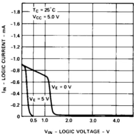
Figure 6. Typical Logic and Decimal Point Input Current vs. Voltage for the 5082-7300 Series Devices. Decimal Point Applies to 5082-7300 and -7302 Only.
Figure 1. Timing Diagram of 5082-7300 Series Logic.
Figure 2. Block Diagram of 5082-7300 Series Logic.
Figure 3. Typical Blanking Control Current vs. Voltage for 5082-7340 Only.
Solid State Over Range
Character
For display applications requiring a ±, 1, or decimal point designa-tion, the 5082-7304 over range character is available. This display module comes in the same package as the 5082-7300 series numeric indicator and is completely compatible with it.
Truth Table for 5082-7304
Typical Driving Circuit for 5082-7304
Package Dimensions
1 2 3 4 8 7 6 5
Absolute Maximum Ratings
Description Symbol Min. Max. Unit
Storage Temperature, Ambient TS -40 +100 °C Operating Temperature, Case TC -20 +85 °C
Forward Current, Each LED IF 10 mA
Reverse Voltage, Each LED VR 4 V
Recommended Operating Conditions
Description Symbol Min. Nom. Max. Unit
LED Supply Voltage VCC 4.5 5.0 5.5 V
Forward Current, Each LED IF 5.0 10 mA
Note:
LED current must be externally limited. Refer to Figure 7 for recommended resistor values.
Recommended Operating Conditions
(TA = -20°C to 70°C, Unless Otherwise Specified)
Description Symbol Test Conditions Min. Typ. Max. Unit
Forward Voltage per LED VF IF = 10 mA 1.6 2.0 V
Power Dissipation PT IF = 10 mA 250 320 mW
All Diodes Lit
Luminous Intensity per LED (Digit Average) IV IF = 6 mA 32 70 µcd
TC = 25°C
Peak Wavelength λPEAK TC = 25°C 655 nm
Dominant Wavelength λd TC = 25°C 30 nm
Weight 0.8 gm
For further information concern-ing electrical and mechanical implementation of the 5082-7300 series devices, please refer to Application Note 934.