Cardinality Enhancement of SAC-OCDMA Systems
Using new Diagonal Double Weight Code
Waqas A. Imtiaz
1, N. Ahmad
21
Department of Electrical Engineering, IQRA National University, Peshawar, Pakistan
2
School of Computer and Communication Engineering, University Malaya Perlis, Malaysia [email protected]
Abstract: Optical code division multiple access (OCDMA)
provides another dimension to multiple access systems, in which each user is assigned a unique code. This allows each subscriber to simultaneously access the medium without any contention. However, simultaneous access of multiple users introduces multiple access interference (MAI) which primarily deteriorates the performance of OCDMA systems. This paper proposes a new code called diagonal double weight (DDW) code to elevate the performance and cardinality of spectral amplitude coding (SAC) OCDMA systems. Performance of our proposed code is evaluated using comprehensive analytical analysis followed by simulation analysis. Examination of bit error rate shows that DDW code along with single photodiode detection technique provides efficient performance, with added benefits of simplified design, large cardinality and ease of implementation.
Keywords: Optical code division multiple access, spectral
amplitude coding, diagonal double weight code, single photodiode detection technique, complementary subtraction detection scheme, cardinality.
1.
Introduction
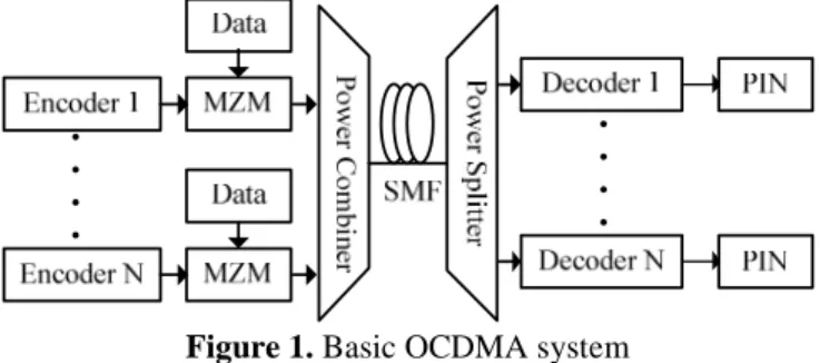
Exponential growth in internet traffic over the last two decades has brought many challenges for network operators, especially in the access domain [1-2]. Optical code division multiple access (OCDMA) systems are anticipated to solve the last mile bottleneck between high-speed metropolitan networks and access networks. OCDMA provides another dimension for multiple access systems, in which each subscriber is assigned a unique code also called an address. Figure 1 show a basic OCDMA system, where each subscriber modulates the data with assigned code word using an encoder. A decoder at the receiving end is used to collect the intended signal. Decision of the received signal is made by correlating with a specific code sequence and passing the total received energy through a threshold device [1].
Figure 1. Basic OCDMA system
Simultaneous access of multiple users allows each subscriber to utilize the entire bandwidth of the fiber optic media. However, it creates problems like multiple access inference (MAI). Multiple access interference is the primary source of performance deterioration in large cardinality OCDMA systems. Efficient coding techniques and robust detector
structures in OCDMA system can efficiently reduce MAI. Spectral amplitude coding (SAC) techniques successfully eliminates MAI and reduces phase induced intensity noise (PIIN) [3]. SAC splits the entire spectrum into bins by an encoder, which is then assigned to individual users in the form of SAC codes based on the set of occupied bins [4]. Another limitation observed in SAC-OCDMA systems is the consumption of extensive bandwidth by lengthy codes. This problem not only limits the number of users, but also introduces complexity in system design. Several codes and detection techniques have been proposed in SAC-OCDMA family to accommodate large number of users while providing an error free transmission. However, the use of a suitable code and detection technique is still an open issue. Enhanced double weight (EDW) code, modified double weight (MDW) code, zero cross correlation (ZCC) code, diagonal eigenvalue unity (DEU) code, and multi diagonal (MD) codes, random diagonal (RD) code, and prime codes etc. have been proposed to develop an efficient SAC-OCDMA system. However, they suffer from drawbacks like long code lengths, increased cross correlation and complexity of implementation [5-12].
This paper discusses the design and implementation of a new code called diagonal double weight (DDW) code, which provides efficient transmission and increased cardinality for SAC-OCDMA systems. Analytical analysis is used at first to analyze the performance of DDW code using two detection techniques: single photodiode detection (SPD) and complementary subtraction detection technique. Bit error rate (BER) and signal to noise ratio (SNR) is used to evaluate the performance of our proposed code. Simulation analysis using Optisystem is then performed to further analyze the performance of DDW code.
Rest of this paper is organized as follows. Section II outlines the design of DDW code, followed by introduction of SPD and complementary subtraction detection techniques in Section III. Section IV gives an analytical analysis followed by simulation analysis of our proposed code in section V. Finally, Section VI concludes the paper.
2.
Design of Diagonal Double Weight Code
An efficient code must provide maximum number of users with minimum code length, flexibility of implementation, ideal cross correlation and effective weights. Using the above mentioned properties three parameters are used to design DDW code (, , ), where represents length of the code, represents the weight, and represents the cross correlation property of the code.
and length of the code respectively. DDW matrix is designed such that:
• Weight of each code is equal to 2.
• Cross correlation between only two codes in a set is equal to 1.
• Length of code is always equal to + 1.
• Combination of 1,2,1 is maintained between only two codes having cross correlation of 1.
Thus, a basic DDW matrix with two codes can be expressed as:
= 1 1 00 1 1 (1) A simple mapping technique is applied to increase the number of users, such that the above mentioned properties remain valid. For 4 users DDW matrix can be expanded as:
=
1 1 0 0 0 0 1 1 0 0 0 0 1 1 0 0 0 0 1 1
(2)
Here = 4, = 5 for = 2. Code word for each user in the system according to (2) becomes:
=
1: , ! 2: !, " 3: ", $ 4: $, %
&
If '(()) denotes the )*+ element of ,ℎ DDW code sequence, then the autocorrelation and cross correlation properties of DDW code can be written as:
∑ '
012 (())'
/()) =
3; 5 = 6
1; 5 ≠ 6
&
(3)Equation (2) and (3) shows that, DDW code has = 1 between only two codes. This significantly minimizes crosstalk between multiple users simultaneously accessing the medium. Equation (2) also shows that code matrix maintains weight position in pairs, therefore a single encoder and decoder with bandwidth twice as that of chip width can implement this code, which simplifies the design of SAC-OCDMA system. Moreover, optimum of DDW code can reduce the use of extensive bandwidth for code implementation during system design. This enables DDW code to accommodate large number of users with minimum impact on system performance.
3.
Spectral
Amplitude
Coding
Detection
Techniques
Detection techniques or signal decoding primarily defines the performance of SAC-OCDMA systems. Efficient implementation of detector structures can significantly reduce system cost, design complexity, MAI, and PIIN effect [13-15]. This section discusses two techniques, which are selected for the analysis of DDW code.
3.1 Single photodiode detection technique
SAC-OCDMA system using SPD technique is shown in Figure 2. Decoder section consists of a low cost fiber-bragg grating (FBG) filter having same spectral response as that of the encoder in order to detect the received signal. The output of FBG is then transferred to the s-decoder, which cancels interfering signals from multiple codes. SPD technique cancels both PIIN and MAI before the received signal is
converted to electrical domain, which significantly elevates the system performance and allows maximum users to simultaneously access the medium [13]. SPD technique using AND mechanism can be mathematically expressed as:
'(()) = )*+689, :; < =:> '/()) = )*+689, :; ? =:> (<?) = ∑ '012 (())'/())
(<?)< = ∑ '012 (())('(())'/())) (<?) − (<?)< =
∑ '012 (())'/()) −∑ '012 (())A'(())'/())B
MZM Encoder
Data
Decoder SMF
011
S-Decoder PIN
Figure 2. Block diagram representation of SAC-OCDMA System with SPD technique
3.2 Complementary Subtraction detection technique
SAC-OCDMA system using complementary subtraction detection technique is shown in Figure 3. It splits the received signal into two branches. One branch contains decoder arrangement with same spectral response as that of the encoder, while another branch contains a C-decoder with opposite spectral response (complement) as compared to the decoder. This enables complementary subtraction detection technique to cancel interfering signals from multiple codes [8]. Outputs from both branches are subtracted after the signal is converted to electrical domain. Complementary subtraction detection scheme can be mathematically expresses as:
'(()) = )*+689, :; < =:> '/()) = )*+689, :; ? =:> (<?) = ∑ '012 (())'/()) (<C?) = ∑ '012 CCCCCCC'((D) /())
(<?) − (<C?) = ∑ '012 (())'/())− ∑ '012 CCCCCCC'((D) /())
Figure 3. Block diagram representation of SAC-OCDMA System with SPD technique
4.
Analytical Analysis
Gaussian approximation is used to analyze SNR and BER of the proposed DDW code for complementary subtraction detection, and SPD techniques. SNR is the average signal to noise power of the received signal: EF = IGHH, where I denotes the current received at the photodiode, and J! represents the variance of the noise signal, given by:
J!= K
Equation (4) can be further elaborated as: J!= 2SK + K!ST+4UVWS
FX
(5)
Noise variance parameters used in (5) are represented in Table 1.
Table 1. Noise variance parameters
Y Charge of Electron
Z Electrical bandwidth noise equivalent
[ Incident current
[\ Power spectral density (PSD) of I
]^ Source coherence time
_` Boltzmann constant
ab Absolute receiver noise temperature
cd Receiver load
It is assumed that maximum electrical bandwidth is much smaller than the total optical bandwidth. Moreover, shot noise and intensity noise collectively follows negative binomial distribution [8][15-16]. Incident current and source coherence time at photodetector output are given by:
K = ℜ f g(h)>hji (6) T = f k(l)
Hml n o
f k(l)mlon H
(7)
Where g(h) represents the PSD of a single sideband optical source and ℜ represents the responsivity of photodiode. ℜ is equal to (p ℎh
q ), where p is the quantum efficiency, ℎ represents the plank’s constant, and h is the central frequency of the broadband optical pulse [17].To analyze the proposed code, it is assumed that:
• Spectrum of each light source is flat over the entire bandwidth.
• Light sources are ideally unpolarized.
• Spectral width of each optical source is identical at the receiver.
• Each user receives same power signal at the receiver. These assumptions are important for mathematical simplicity and analysis of our proposed code. Without these assumptions, the system becomes difficult to analyze [6][8].
4.1 SNR single photodiode detection technique
If '5()) denotes the ),ℎ element of ,ℎ DDW code sequence, then the property of DDW code for SPD detection technique using AND subtraction becomes:
∑
)=1'5(
))
'6(
))
=r
; 5 = 61; 5 ≠ 6&
(8)And
∑
)=1'5(
))
('5(
))
'6(
))
) =r
1; 5 = 61; 5 ≠ 6&
(9)Therefore, the output of SPD technique using (8) and (9) can be written as:
3 ∑
)=1'5(
))
'6(
))
−∑
)=1'5(
))
('5(
))
'6(
))
)s
=r
− 1; 5 = 6
0; 5 ≠ 6
&
(10)Now PSD at the receiving end during one-bit period, for SPD technique is equal to:
g(h) =Ntu
∆l∑w(2 >(x ∑ '(
())'/()) − 0
12
∑ '012 (())('(())'/()))y r ∆l
0z
(11)
Where {LP is the power received from a single optical source, ∆h represents the optical source bandwidth in hertz, and (h) represents a unit step function. Current received at PIN photodiode during a single bit period can be determined by integrating equation (11).
= f Ntu
∆l∑w(2 >(x
∑ '012 (())'/()) − ∑ '012 (())A
'
())'/())By ij r ∆l0z >h
(12) Using (8), (9), and
∑
5=1>5= [10], (12) can be simplified as:=Ntu|
0 } + 1~ − Ntu|
0 }1 + 1~ =Ntu|
0 } + 1~ − Ntu|
0 }1 + 1~
f
0∞g(
h)
>h={( − 1) (13)
Now the total incident current using (13), becomes: K = ℜNtu|
0 ( − 1) (14)
Shot noise power at the receiving photodiode for SPD technique can be determined using (5) and (14):
Kℎ:,2 = 2Sℜ{( − 1) (15)
The noise power of PIIN while using (7), is equal to: K2{KK = ℜ2
f
0∞g(
h)
>h
2S f g(h)2>h ∞ 0
f0∞g(h)>h2>h
(16)
After simplification:
K{KK2 = ℜ2S
f
0∞g(h)2>h (17)For SPD using a single PIN,
f
0∞g(h)2>h is equal to: = NtuH0∆l∑ '012 /())}∑w(2 >('(())~}∑wQ2 >Q'Q())~ −NtuH
0∆l∑ ('012 (())'/()))}∑w(2 >('(())~}∑wQ2 >Q'Q())~
(18) By using the average value of
∑
5=1'5(
))
=[16], (18)
becomes: =NtuH|
0∆l w|
0 ∑ }∑ 'w(2 012 (())'/())~− {2
∆h
∑ ∑
5=1 )=1'5(
))
('5(
))
'6(
))
) (19)Using correlation properties of DDW code for SPD technique, (19) can be further simplified as:
=NtuH|
0∆l w|
0 } + 1~ − NtuH|
0∆l w|
0 }1 + 1~
f
∞g(h)2>h0 =
{22
2∆h ( − 1)
(20) Using (20), total PIIN noise power becomes:
K{KK2 =ℜ
2S{ 22
2∆h ( − 1)
(21)
Now using (5), (14), (15) and (21), total EF for the proposed DDW code, when probability of each user sending bit “1” at any instant is ½ becomes:
EF = ℜHtuHH H(| )H Hℜtu
4.2 SNR for Complementary subtraction detection technique
If '(()) denotes the )*+ element of ,ℎ DDW code sequence, then the property of DDW code for complementary subtraction detection technique can be written as:
∑ '012 (())'/()) =3; 5 = 61; 5 ≠ 6& (23) And
∑ '012 CCCCCCC'((D) /()) =31; 5 = 61; 5 ≠ 6& (24)
Therefore, the output of complementary subtraction detection technique using (23) and (24) becomes:
∑ '012 (())'()) −
∑ '012 CCCCCCC'((D) /()) = 3 − 1; 5 = 60; 5 ≠ 6
&
PSD at the receiving end during one-bit period, for PIN1 and PIN2 is equal to:
g (h) =Ntu
∆l∑w(2 >(∑ '012 (())'/()) r ∆l
0z
(25) g!(h) =N∆ltu∑w(2 >(∑ '012 CCCCCCC'((D) /()) r ∆l0z
(26) The amount of current received at PIN1 and PIN2 during a single bit period can be determined by integrating equation (25) and (26):
f gji (h)>h= f Ntu
∆l∑w(2 >(∑ '012 (())'/()) r ∆l
0z i
j >h
(27) f gji !(h)>h =
f Ntu
∆l∑w(2 >(∑ '012 CCCCCCC'((D) /())) r ∆l
0z i
j >h (28)
Using (23) and (24), (27) and (28) can be simplified as: f gji (h) >h=Ntu|
0 } + 1~ f gji (h)>h =Ntu|
0 } + 1~ (29) f gji !(h)>h =Ntu0|}1 + 1~
f gji !(h)>h =Ntu0|}1 + 1~ (30) The total received current can be written as:
K = ℜ f gji (h)− ℜ f gji !(h) (31) K =ℜNtu|
0 ( − 1) (32)
Shot noise power can be determined using (5), (29) and (30): KL+M*! = 2Sℜ f gji (h) >h+ ℜ f gji !(h)>h (33)
KL+M*! = 2Sℜ Ntu0|( + 1) +Ntu0|(1 + 1) (34) KL+M*! = 2SℜNtu0|( + 3) (35)
PIIN noise power for complementary subtraction detection technique can be determined as:
KNGG0! = ℜ!Sf gji (h)!>h+ f gji !(h)!>h (36) f gi (h)!>h
j and f gji !(h)!>h can be written as: f gi (h)!>h
j = Ntu
H
0∆l∑ '/
())}∑w(2 >('(())~ }∑wQ2 >Q'Q())~ 0
12 >h
f gji !(h)!>h= NtuH
0∆l∑ '12 0 /()))∑w(2 >(CCCCCCC}∑'((D) wQ2 >Q'Q())~>h
Now:
f g (h)!>h =NtuH|
0∆l w|
0 ∑ }∑ 'w(2 012 (())'/())~ i
j
f gji !(h)!>h= Ntu
H|
0∆l w|
0 ∑ ∑ 'w(2 012 CCCCCCC'((D) /()) f gi (h)!>h
j =Ntu
H|
0∆l w|
0 } + 1~ (37) g!(h)!>h
i
j =
{LP!
∆h }1 + 1~
(38)
Therefore, the total PIIN noise power due to Complementary subtraction detection technique using (37) and (38) becomes:
KNGG0! = ℜ!SNtu
H|
0∆l w|
0 ( + 3)
(39) Now using (5), (32), (35) and (39), the total SNR for the proposed DDW code using complementary subtraction detection, when probability of sending bit “1” by each subscriber at any instant is ½ becomes:
EF = ℜHtuHH H(| )H Hℜtu
(|")ℜHtuHH∆H H(|") (40) Using Gaussian approximation, BER can be expressed as:
EF =12 ;=EF 8
(41)
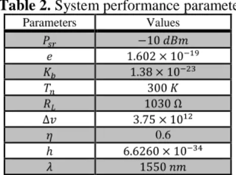
Figure 3 and 4 shows the performance of DDW code using complementary subtraction detection and SPD scheme, based on system performance parameters in Table 2. Analysis is performed at 622 Mbps of data and -10 dBm of received power, while BER and SNR using (22), (40), (41) are observed against different number of subscribers.
Table 2. System performance parameters
Parameters Values
{LP −10 >S8
1.602 × 10
U 1.38 × 10!"
VW 300
FX 1030 Ω
∆h 3.75 × 10 !
p 0.6
ℎ 6.6260 × 10"$
1550 98
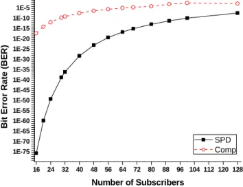
It is shown that SNR and BER are interrelated, that is BER of the received signal increases as SNR decreases. Results also show that DDW code using SPD technique provides better performance in terms of SNR and BER as compared to complementary subtraction detection technique. It is evident from the fact that SPD eliminates MAI and PIIN in optical domain, which elevates the quality of the received signal. It is also observed that BER increases as we increase the number of users, and performance of DDW using SPD scheme deteriorates respectively. However, it is still able to maintain efficient communication with SF < 10, at large number of users. Therefore, DDW code suing SPD technique is an efficient choice for the implementation of next generation OCDMA networks.
BER with received power for 32 and 64 users only at 622 Mbps of data. Figure shows that our proposed code is able to provide efficient performance at effective received power of -15 dBm and above. This is because the interference from other users is reduced in DDW code due to its fixed cross correlation property, which significantly reduces PIIN and elevates system performance [8]. This enables our proposed code to provide efficient performance even at small received powers.
Figure 6 shows the performance of DDW code using SPD technique for different data rates at -10 dBm received power and 32 active subscribers. It is shown that our proposed code is able to provide efficient transmission of 2.5 Gbps of data while maintaining the nominal SF ≤ 10 criteria.
16 32 48 64 80 96 112 128
0 200 400 600 800 1000 1200 1400
S
ig
n
a
l
to
N
o
is
e
R
a
ti
o
(
S
N
R
)
Number of Subscribers
SPD Comp
Figure 3. SNR vs. No. of subscribers for DDW code using SPD and complementary subtraction detection techniques
16 24 32 40 48 56 64 72 80 88 96 104 112 120 128 1E-75
1E-70 1E-65 1E-60 1E-55 1E-50 1E-45 1E-40 1E-35 1E-30 1E-25 1E-20 1E-15 1E-10 1E-5
B
it
E
rr
o
r
R
a
te
(
B
E
R
)
Number of Subscribers
SPD Comp
Figure 4. BER vs. No. of subscribers for DDW code using SPD and complementary subtraction detection techniques Figure also shows that as we increase the amount of data, BER increases because pulse width is inversely proportional to bit rate. As bit rate increases pulse width decreases and the overall system becomes more sensitive to dispersion effect [12]. However, the proposed code is able to perform efficiently up to 2.5 Gbps of data.
0 dBm -5 dBm -10 dBm -15 dBm -20 dBm 1E-45
1E-40 1E-35 1E-30 1E-25 1E-20 1E-15 1E-10 1E-5
B
it
E
rr
o
r
R
a
te
(
B
E
R
)
Received Power
32 Users 64 Users
Figure 5. BER vs. {LP for DDW code using SPD technique
0.5 0.622 0.75 1 1.5 2 2.5 5
1E-47 1E-44 1E-41 1E-38 1E-35 1E-32 1E-29 1E-26 1E-23 1E-20 1E-17 1E-14 1E-11 1E-8 1E-5
B
it
E
rr
o
r
R
a
te
(
B
E
R
)
Data Rate (Gbps)
SPD
Figure 6. BER vs. data rate for DDW code using SPD technique at -10 dBm and 32 users
5.
Simulation Analysis
Optisystem is used to evaluate the performance of DDW code using SPD technique. For a single user, the transmitter consists of a laser, which is encoded using multiplexer encoder. Wavelengths assigned to first user are = 1550 98 and != 1550.3 98 respectively. Thus, chip length assigned to each user is 0.3 98 per chip. Output of the encoder is then modulated with a pseudo random bit sequence (PRBS) generator using Mach-Zehnder Modulator (MZM). Output of MZM is applied to an ideal multiplexer and single mode fiber (SMF). Decoder architecture for SPD technique consists of FBG filters used in reflection with 0.3 98 bandwidth as shown in Figure 7. PIN photodiodes are used to convert the signal from optical to electrical domain. A low pass electrical Bessel filter with an electrical bandwidth of 75 % of applied bit rate is also used at the receiver.
-+
FBG 1 FBG 2 FBG 3
Decoder S- Decoder
PD
Figure 7. Schematic diagram for SPD decoder
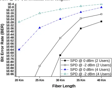
Figure 8 shows the performance of SAC-OCDMA system using DDW code with SPD technique at different fiber lengths. Analysis is performed for 2 and 4 users at the input powers of 0 dBm and -2dBm, and 2.5 Gbps of data. BER of randomly selected user is plotted to analyze the performance of our proposed code. It is shown that SPD technique provides better performance in terms of BER for 2 users at 0dBm. Figure also shows that, as we increase fiber length and number of active users, BER increases. This is because of dispersion across the media, which is proportional to fiber length. However, BER analysis shows that DDW code using SPD technique is able to provide efficient performance with SF ≤ 10, at nominal fiber lengths.
20 Km 25 Km 30 Km 35 Km 40 Km
1E-96 1E-92 1E-88 1E-84 1E-80 1E-76 1E-72 1E-68 1E-64 1E-60 1E-56 1E-52 1E-48 1E-44 1E-40 1E-36 1E-32 1E-28 1E-24 1E-20 1E-16 1E-12 1E-8 1E-4
B
it
E
rr
o
r
R
a
te
(
B
E
R
)
Fiber Length
SPD @ 0 dBm (2 Users) SPD @ -2 dBm (2 Users) SPD @ 0 dBm (4 Users) SPD @ -2 dBm (4 Users)
Figure 8. BER vs. fiber length for DDW code using SPD technique
Figure 9 shows the eye patterns for DDW code using SPD technique at 0 >S8. Tests are made over 20 km, and 40 Km long SMF, at bit rate of 2.5 Gbps using 2 active subscribers. Eyes openings indicate the degree of distortion at the receiving end that is less opening of the eye indicates a high level of distortion [4]. It is evident from eye openings that distortion across the media increases as we increase fiber length.
(a) (b)
Figure 9. Eye patterns for DDW code using SPD technique at (a) 0 dBm @ 20 Km and (b) 0 dBm @ 40 Km
6.
Conclusions
Simultaneous access of multiple users introduces multiple access interference, which primarily deteriorates the performance of SAC-OCDMA systems. Moreover, long code in SAC family limits the amount of users while complicating system implementation. This paper proposes a new code called diagonal double weight code that provides efficient performance while maintaining scalability in SAC-OCDMA systems. Performance of our proposed code is analyzed using detailed analytical analysis, which specifies that DDW code provide efficient performance with SPD scheme while supporting large number of users as compared to complementary subtraction detection scheme. Simulation analysis also proves that DDW code using SPD technique is able to maintain efficient transmission with SF ≤ 10. Therefore, it can be concluded that our proposed code using single photodiode detection technique can efficiently support next generation access networks with added benefits of large cardinality, simplified design, minimum cost and ease of implementation.
References
[1] L. Verma, P.S. Mundra, “Major Technical Concerns in the Practical Realization of FO-OCDMA Networks”, International Journal of Computer Science and Engineering Technology”, Vol. 5, No. 2, pp. 63-66, 2014.
[2] R. Roka, F. Certik, “Modeling of Environmental Influences at the signal transmission in optical transmission medium”, International Journal of Communication Networks and Information Security (IJCNIS), Vol. 4, No. 3, pp.144-162, 2012.
[3] N. Ahmed, S.A. Aljunid, R.D. Ahmad, “Novel OCDMA Detection Technique based on Modified Double Weight Code for Optical Access Network”, ELEKTRONIKA IR ELEKTROTECHNIKA, Vol. 18, No. 8, pp. 117-121, 2012.
[4] J. Penon, S. Ayottee, L.A. Rusch, “Incoherent SAC OCDMA Systems at 7x622 Mbps”, Conference on Lasers an Electro-Optics, pp.610-611, United States, 2007.
[5] C. Rashidi, S.A. Aljunid, “Cardinality Enhancement Using Flexible Cross Correlation (FCC) Code for SAC-OCDMA Systems by Alleviation Interference Scheme (AIS)”, Optik-International Journal of Light and Electron Optics, Vol. 125, No. 17, pp. 4889-4894, 2014.
[6] A.F. Hilal, S.A. Aljunid, R.B. Ahmad, “Performance of random diagonal code for OCDMA systems using new spectral direct detection technique”, Optical Fiber Technology, Vol. 15, pp. 283-289, 2009.
[7] L. Xiaobin, S. Yongjie, “Construction of variable weight optical orthogonal codes for OCDMA Passive Optical networks”, 8th International Conference on Wireless Communication, Networking and Computing, pp. 1-4, China, 2012.
[8] Y.A. Hassan, K.S. Nisar, “Diagonal Eigenvalue Unity (DEU) code for Spectral Amplitude Coding- Optical Code Division Multiple Access”, Optical Fiber Technology, Vol. 19, No. 4, pp. 335-347, 2013.
dynamic cyclic shift code”, Ukr. J. Phys. Opt, Vol. 13, No. 1, pp. 12-17, 2013.
[10]T.H. Abd, S.A. Aljunid, H.A. Fadhil, “Development of a new code family based on SAC-OCDMA system with large cardinality for OCDMA network”, Optical Fiber Technology, 2011, Vol. 17, No. 4, pp. 273-280. [11]C.B.M. Rashidi, S.A. Aljunid, “Cardinality
enhancement using flexible cross correlation (FCC) code for amplitude coding optical code division multiple access systems”, Journal of Applied Sciences Research, Vol. 8, No. 12, pp. 5614-5626, 2012.
[12]M.Z. Norazimah, S.A. Aljunid, “Analytical Comparison of Various SAC-OCDMA Detection Techniques” IEEE 2nd Conference on Photonics, Kuala Lumpur, Kata Kinabalu, pp. 1-4, 2011.
[13]M.R. Hamza, S.A. Aljunid, “Improving Spectral Efficiency of SAC-OCDMA Systems by SPD Scheme”, IEICE Electronic Express, Vol. 9, No. 24, pp. 1829-1834, 2012.
[14]A. Somaya, A.F. Heba, “SAC-OCDMA Systems Using Direct Detection Technique”, IOSR Journal of Electronics and Communication Engineering, Vol. 9, No. 2, pp. 55-60, 2014.
[15]R.K.Z. Sahbudin, M.K. Abdullah, “Performance Improvement of Hybrid Subcarrier Multiplexing Optical Code Division Multiplexing System Using Spectral Direct Decoding Detection Technique” Optical Fiber Technology, Vol. 15, No. 3, pp. 266-273, 2009. [16]Z. Wei, H. M. H. Shalaby, “Modified Quadratic
Congruence Codes for Fiber Bragg-Grating-Based Spectral-Amplitude-Coding Optical CDMA Systems”, Journal of Light Wave Technology, Vol. 19, No. 9, pp. 1274-1281, 2001.