Taping, Labeling, Storage, Packing and Marking
Vishay Semiconductor Standard Bar Code Labels
Standard bar code labels for finished goods
The standard bar code labels are product labels and
used for identification of goods. The finished goods
are packed in final packing area. The standard
packing units are labeled with standard bar code
(3-of-9 bar code (code 39) conforming
MIL-STD-1189) before transported as finished goods to
warehouses. The labels are on each packing unit with
Vishay Semiconductor GmbH specific data. The
content of the label is show in the following table and
figure 1.
In future a change from 1D to 2D bar codes can be
expected. That one will look like as shown in
figure 2.
For transceivers the following logos are used inside
the bar code label which are shown in figure 3.
The following lead (Pb)-free categories (see figure 1
to figure 3) are meant to describe the lead (Pb)-free
2
ndlevel interconnect terminal finish/material of
components and/or the solder used in board
assembly.
e1 SnAgCu (shall not be included in category 2) e2 Sn alloys with no Bi or Zn excluding SnAgCu
e3 Sn
e4 Precious metal (e.g. Ag, Au, NiPd, NiPdAu) (no Sn) e5 SnZn, SnZnx (no Bi)
e6 contains Bi
e7 low temperature solder (≤ 150 °C) containing Indium (no Bi)
e0, e8, e9 symbol are unassigned
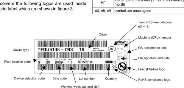
Figure 1. Bar Code Label, Detailed Description
Lead (Pb)-free category e3 – Sn
Machine (CPU) number
QA acceptance seal
QA signature and date
Lead (Pb)-free logo
RoHS compliance logo Device selection code Date code
Working week day and shift
Lot number Quantity Plant location code
Device type
Origin
Remark: Multi - Date Codes would be marked in the QA field of this label on top of the lead 19873
Figure 2. 2D Bar Code Label (according the Bar Code Standard for 2D Label PDF 417) for a Lead (Pb)-free Device, Equivalent to that
Shown in Figure 11.
19874
Figure 3. Logos Inside the Label
Terminations
Lead (Pb)-free designed
Totally
ESD Lead (Pb)-free categories
Lead (Pb)-free designed
Moisture Proof Packing
The reel with the taped components is packed in a
moisture proof aluminum bag to protect the devices
from absorbing moisture during transportation and
storage. This bag finally is packed in a cardboard box.
On the reel as well as on the bag and the box are
labels, which are described in the following (see figure
4). This is an example and little variations may be
between different plants.
Inside the aluminum bag is with the reel a desiccant
bag and a humidity indicator (figure 5).
On the reel are the bar code product label and taping
label (figure 7) and a yellow ESD sticker (figure 6).
Pb-free information is part of the bar code label, but
when it is missing there a "lead (Pb)-free"
-label (figure 8) may be attached. In addition the
"Moisture-Sensitive Identification Label (MSID)" is
applied (figure 9).
Figure 4. Moisture Proof Packing
Figure 5. Desiccant Bag (example, left) and Humidity Indicator Card
Figure 6. ESD Sticker
Reel Aluminum bag Moisture level sticker 0 Bar code label ESD sticker 18298 Box
19878 19879
Figure 7. Product (Top) and Taping Label
Figure 8. Lead (Pb)-free Logo
Figure 9. Moisture-Sensitive Identification Label (MSID) 19880
19881
On the bag the same stickers as on the reel will be
shown. In addition there the moisture-sensitivity
caution label as shown in figure 10 describes the
storage and drying procedures.
In the following two reels of different size are shown
with the labeling (figure 11 and figure 12).
Final Packing
The sealed reel is packed into a cardboard box, which
is 334 x 335 x 40 mm
3in size. A secondary cardboard
box is used for shipping purposes, with the following
sizes, slightly different for different production
locations, see the following tables.
Table 2. Secondary boxes Malaysia, location code 68
Philippines, location code 19
On the boxes the same labels as on the bag will be
found.
Recommended Method of Storage
Dry box storage is recommended as soon as the dry
bag has been opened to prevent moisture absorption.
The following conditions should be observed, if dry
boxes are not available:
• Storage temperature 10
°
C to 30
°
C
• Storage humidity
≤
60 % RH max.
After more than 72 h under these conditions moisture
content will be too high for reflow soldering. In case of
moisture absorption, the devices will recover to the
former condition by drying under the conditions given
in the label on the aluminum bag as shown in figure 5.
Such an EIA JEDEC standard JSTD-020 level 4 label
is included on all dry bags (see figure 10).
Figure 10. EIA JEDEC Standard JSTD-020 Level 4 Label is included on all Dry Bags
Figure 11. 180-mm Reel with Labels. No Labels on the rear. Lead (Pb)-free Marking is not on the Bar Code; here an additional Lead
(Pb)-free Sticker is applied.
CAUTION
This bag contains
MOISTURE-SENSITIVE DEVICES 1. Shelf life in sealed bag: 12 months at < 40 °C and < 90 % relative humidity (RH)
2. After this bag is opened, devices that will be subjected to soldering reflow or equivalent processing (peak package body temp. 260 °C) must be
2a. Mounted within 72 hours at factory condition of < 30 °C/60 % RH or 2b. Stored at < 5 % RH
3. Devices require baking befor mounting if:
Humidity Indicator Card is > 10 %when read at 23 °C ± 5 °C or 2a. or 2b. are not met.
4. If baking is required, devices may be baked for:
192 hours at 40 °C + 5 °C/- 0 °C and < 5 % RH (dry air/nitrogen) or 96 hours at 60 °C ± 5 °C and < 5 % RH for all device containers or 24 hours at 125 °C ± 5 °C not suitable for reels or tubes Bag Seal Date:
(If blank, see barcode label)
Note: Level and body temperature defined by EIA JEDEC Standard JSTD-020
4
LEVEL19889
Figure 12. 330-mm Reel with Labels. No Labels on the Rear. Lead (Pb)-free Information is on the Bar Code Label.
Size, Length x Width x Heigth
mm x mm x mm Quantity of Boxes 360 x 360 x 45 1 360 x 360 x 120 2 360 x 360 x 200 5 360 x 360 x 340 8 675 x 355 x 375 16 620 x 530 x 480 26 625 x 525 x 640 30 1000 x 600 x 580 60
Size, Length x Width x Heigth
mm x mm x mm Quantity of Boxes
360 x 360 x 130 2
380 x 380 x 260 5
370 x 360 x 620 11
ESD Precaution
Proper storage and handling procedures should be
followed to prevent ESD damage to the devices
especially when these are removed from the antistatic
shielding bag. “Electro-static sensitive
devices”-warning labels (figure 6) are affixed on the packaging.
Order Information, Related Packing Units, Tape and Reel Size and Labeling
In this document the packing and labeling information for IR transceivers is compiled.
Table1. Transceiver tape drawing and reel size reference according to type order text
Part Description Quantity/Reel Tape Reel
Orientation in tape for mounting Pcs Drawing-no. Reel no in reel table
TFBS2711X01-TR1 Side view 1000 16 1 TFBS2711X01-TR3 Side view 2500 16 2 TFBS4601-TR1 Side view 1000 14 1 TFBS4601-TR3 Side view 2500 14 2 TFBS4650-TR1 Side view 1000 14 1 TFBS4650-TR3 Side view 2500 14 2 TFBS4650-TR4 Side view 6000 15 2 TFBS4650-TT3 Top view 2500 26 2 TFBS4652-TR1 Side view 1000 14 2 TFBS4652-TR3 Side view 2500 14 2 TFBS4656-TR1 Side view 1000 14 2 TFBS4656-TR3 Side view 2500 14 2 TFBS4701-TR1 Side view 1000 16 1 TFBS4701-TR3 Side view 2500 16 2 TFBS4710-TR1 Side view 1000 20 2 TFBS4711-TT1 Top view 1000 17 1 TFBS4711-TR1 Side view 1000 16 1 TFBS4711-TR3 Side view 2500 16 2 TFBS5700-TR3 Side view 2500 14 2 TFBS6626-TR1 Side view 1000 14 2 TFBS6626-TR3 Side view 2500 14 2 TFBS6711-TR1 Side view 1000 16 1 TFBS6711-TR3 Side view 2500 16 2 TFBS6711-TT1 Top view 1000 17 1 TFBS6711-TT3 Top view 2500 17 2
TFBU4101-TR3 Side view 1000 22 3
TFBU4101-TT3 Top view 1000 23 3
TFDU4300-TR1 Side view 750 18 1
TFDU2201-TR1 Side view 750 21 1
TFDU2201-TR3 Side view 2250 21 2
TFDU4300-TR3 Side view 2500 18 2
TFDU4300-TT1 Top view 750 19 1
TFDU4300-TT3 Top view 2500 19 2
TFDU6300-TR3 Side view 2500 18 2
TFDU6300-TT3 Top view 2500 19 2
TFDU6301-TR3 Side view 2500 18 2
TFDU6301-TT3 Top view 2500 19 2
TFDU6103-TR3 Side view 1000 22 3
TFDU6103-TT3 Top view 1000 23 3
TFDU6126-TR3 Side view 1000 22 3
TFDU6126-TT3 Top view 1000 23 3
TFDU8108-TR3 Side view 1000 22 3
TFDU8108-TT3 Top view 1000 23 3
TOIM4232-TR3 Top view 1500 24 2
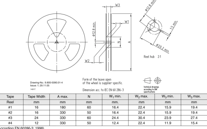
Shape of Reel and Dimensions
in mm
(According EN 60286-3: 1998)
Leader and Trailer Dimensions
in mm
Cover Tape Peel Strength
According to IEC 286
Peel Strength: 0.1 N to 1.3 N
(300
±
10 %) mm/min
165
° το
180
°
peel angle
Tape Tape Width A max. N W1 min. W2 max. W3 min. W3 max.
Reel mm mm mm mm. mm mm mm #1 16 180 60 16.4 22.4 15.9 19.4 #2 16 330 50 16.4 22.4 15.9 19.4 #3 24 330 60 24.4 30.4 23.9 27.4 #4 12 330 50 12.4 22.4 11.9 15.4 14017
Drawing-No.: 9.800-5090.01-4 Issue: 1; 29.11.05
Figure 13. Leader and Trailer
Trailer Leader no devices min. 200 min. 400 Start End devices 96 11818 no devices
Tape Dimensions
in mm
Figure 14. Tape for 1.6 - mm Package Side View Oriented
19783
Figure 15. Tape for 1.6 - mm Package Side View Oriented for TR-4 Version
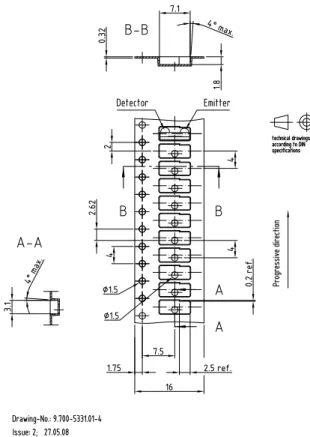
Figure 16. Tape for 1.9 - mm Package Side View Oriented 19613
Figure 17. Tape for 1.9 - mm Package Top View Oriented 20416
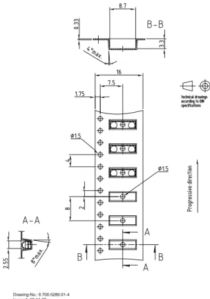
Figure 18. Tape for 2.5 - mm Package Side View Oriented 19856
19856
Drawing-No.: 9.700-5279.01-4 Issue: 1; 08.12.04
Figure 19. Tape for 2.5 - mm Package Top View Oriented 19855
Drawing-No.: 9.700-5280.01-4 Issue: 1; 03.11.03
Figure 20. Tape for 2.74 - mm Package Side View Oriented 19805
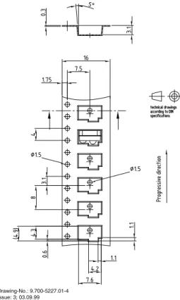
Figure 21. Tape for 2.75 - mm Package Side View Oriented 19870
Drawing-No.: 9.700-5227.01-4 Issue: 3; 03.09.99
Figure 22. Tape for 4.0 - mm Package Side View Oriented 19875
Figure 23. Tape for 4.0 - mm Package Top View Oriented 19824
Drawing-No.: 9.700-5251.01-4 Issue: 3; 02.09.05
Figure 24. Tape for SO - 16 Package Top View Oriented
18241
Figure 25. Tape for QFN20-4, 4 mm x 4 mm
Marking of Transceiver Modules
Figure 26. Tape for 1.6 - mm Package Top View Oriented 21663
Drawing-No.: 9.700-5340.01-4 Issue: 1; 15.01.09 Progressi v e direction specifications according to DIN
technical drawings
4 0.32 16 7.5 1.75 3.1 2 7.1 Emitter Detector 2 8 Ø 1.5 Ø 1.5 2 4° max. 8° max.