A Device-Based Process Signal Design
of Electric Power Plants
Juraj Simunic
1, Mirko Randic
2, Marijana Zivic
31Technical faculty, University of Rijeka, Rijeka, Croatia
2Faculty of Electrical Engineering and Computing, University of Zagreb, Zagreb, Croatia 3Technical faculty, University of Rijeka, Rijeka, Croatia
Automation and computerized control of processes in electric power plants were intensively started at the end of seventies and at the beginning of eighties dur-ing the introduction of microprocessor–based computer systems. The first generation of the information pro-cessing equipment has in most cases already become disused. From that time, visibility of controlled pro-cess has been increased by installing new and modern devices which enable better informing about all relevant events. The increased quantity of information by which processes can be described implies that new and more efficient techniques for information modeling should be developed.
In this paper a device-based approach to process infor-mation modeling is proposed. Such modeling approach is more efficient than function-based approach we used before. The efficiency lies in the fact that device-based approach is in the very essence an object-oriented mod-eling approach. Therefore, device-based information models can be easily mapped to object-oriented mod-els. Both function-based and device-based modeling approaches are described in the paper and differences between two modeling paradigms are emphasized. In the last Chapter of the paper analogy between device-based and object-oriented models is described. This analogy represents basis for the model mapping.
Keywords: electric power plant, information modeling, process signal base, device-based model, object-oriented model
1. Introduction
The starting point for electric power plant(EPP)
modeling for the needs of building an attached building and maintenance of the automation and control system is a process information model-ing. Structure of information and information flows between the controlled power plant and control system must be known. Determination
of the data and signals structure of the informa-tion flows is a very complicated task even for small EPPs.
There are problems arising out of: equipment diversity used in EPPs;
complexity of technological process in con-trolled systems, which surpasses knowledge of a single person and thus sets up an imper-ative to organize a group of people(experts)
for a particular part of the process technol-ogy;
a relatively great number of signals which interchange between controlled and control systems;
a need for good expertness in concrete EPP and its specific qualities.
In Chapter 2 of the paper, the function-based modeling of process signals is presented. Such modeling approach is technology-dependent, and now we are treating it as an obsolete ap-proach. Nevertheless, a short description of the approach is included here because device-based approach is partly device-based on it. Thus, a reader can consider the evolution of our model-ing paradigm more easily. The function-based approach has been used for information mod-eling of processes in EPPs during the years of our projects8]. In Chapter 3, methodology for
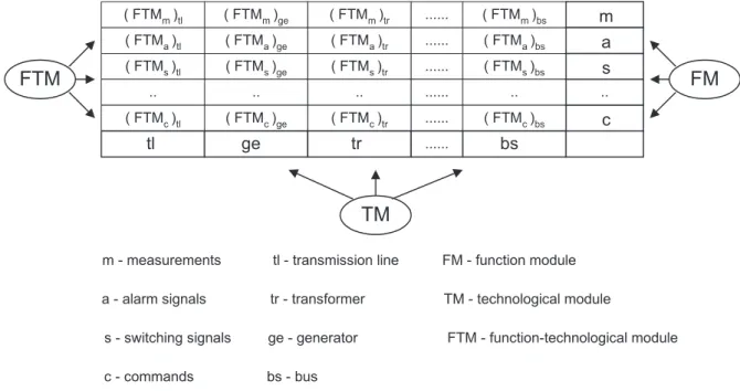
Fig. 1.Function-based EPP process signal model.
the observed EPP is obtained in a modular and optimal way. Besides, it is underlined in Chap-ter 4 that the describeddevices-basedmodeling fits into modernobject-orientedmodeling ap-proach. How the device-based model could be mapped into object-oriented model is also ex-plained in this chapter.
2. Function-Based Process Signal Model
The function-based process signal model rep-resents the first generation process signal de-sign, which originates from the beginning of
the eighties. It is based on the technological modulesof an EPP, along with signals by their
function in the EPP process (Figure 1). By
such a model, EPP process signals are defined according to their location (particular
techno-logical module in the EPP) and function i.e.
signal function in the EPP operation descrip-tion. Technological modules are considered as sources and sinks of signals, and signals are categorized by their function. In the model, function-technological module (FTM) is used
as a base for signal structure definition. The generator commands or transformer alarm sig-nals are examples of the FTMs(Table 1).
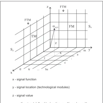
By introducing the third aspect of a signal — the signal value, the corresponding EPP signal structure is defined as a three-dimensional vec-tor(Figure 2).
The set of signalsSFT on the level of an EPP
for all technological modules and for all types of signals can be defined as:
(1)
SFT =fαxyzg x=1 2 3 ::: m
y=1 2 3 ::: n
z=0 1 2 ::: r
whereαxyzpresents the signal defined by
func-tionx, locationyand valuez. The signal subset
Sxrepresents all signals of one FM from all
tech-nological modules of an EPP. It can be defined by the equation (1) with x = cons. yz-plane
in Figure 2 relates to this subset. The signal subsetSy represents all signals of all FM from
one technological module of an EPP. It can also be defined by the equation(1) withy = cons.
(xz-plane from Figure 2). Finally, the subset
Sxy(FTM)depicts all signals from one
techno-logical module and for one signal quality i. e. function. It can also be defined by the equation
(1), but withx =cons. andy =cons.
Fig. 2.EPP signal representation by vector.
Model of process signal structure organized in the above-mentioned way and defined at the
level of an EPP, can be used for EPP opera-tion analysis and for estimaopera-tion of various in-formation flows. However, it has some specific limitations and drawbacks, as follows:
Process signals are organized at the level of technological modules in EPP,the complete procedure has to be repeated for each EPP. The model is not independent of the EPP. Moreover, modular design is not possi-ble.
Device, as a basic EPP component, is not separatedas an information bearing unit.
Device statescannot be defined for the needs of a modern process signal design, and the links among devices cannot be determined either.
Redundancy of the data entry is signifi-cantly greater.
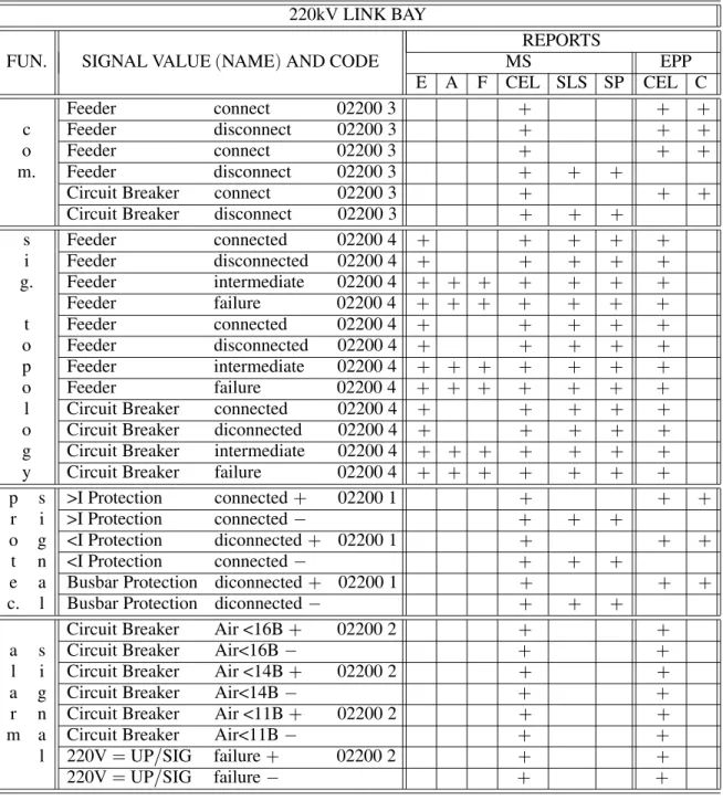
As an example, one part of process signal base generated by function-based modeling approach is presented in Table 2. The records are ex-tended with additional data-encoded parameter and with the denoted places for signal usage
(third column – REPORTS). The first column
denotes the signal function; signals are grouped according to their function. The second column represents signal value and the signal code. In the third column, locations for sending signals or location within the EPP or in master sub-station (MS) are marked. Reports can be
ob-tained from event list(E), alarm list(A), fault
list(F), chronological event list (CEL), single
line scheme (SLS), cabinet (C) and synoptic
chart(SP).
Three-dimensional signal encoding is based on the following principle:
the first group of digits (y dimension from
the model)is divided into three subgroups:
the first subgroup consists of two digits and it marks the bay (01 – Feeder bay,
02 – Link bay,:::);
the second subgroup consists of one digit and denotes voltage level of the observed bay(1 – 110 kV, 2 – 220 kV, 3 – 35 kV);
the third subgroup is made up of two dig-its and marks the bay name(01 – Melina
1, 02 – Melina 2,:::), it is used if there
220kV LINK BAY
REPORTS
FUN. SIGNAL VALUE(NAME)AND CODE MS EPP
E A F CEL SLS SP CEL C
Feeder connect 02200 3 + + +
c Feeder disconnect 02200 3 + + +
o Feeder connect 02200 3 + + +
m. Feeder disconnect 02200 3 + + +
Circuit Breaker connect 02200 3 + + +
Circuit Breaker disconnect 02200 3 + + +
s Feeder connected 02200 4 + + + + +
i Feeder disconnected 02200 4 + + + + +
g. Feeder intermediate 02200 4 + + + + + + +
Feeder failure 02200 4 + + + + + + +
t Feeder connected 02200 4 + + + + +
o Feeder disconnected 02200 4 + + + + +
p Feeder intermediate 02200 4 + + + + + + +
o Feeder failure 02200 4 + + + + + + +
l Circuit Breaker connected 02200 4 + + + + +
o Circuit Breaker diconnected 02200 4 + + + + +
g Circuit Breaker intermediate 02200 4 + + + + + + +
y Circuit Breaker failure 02200 4 + + + + + + +
p s >I Protection connected+ 02200 1 + + +
r i >I Protection connected; + + +
o g <I Protection diconnected+ 02200 1 + + +
t n <I Protection connected; + + +
e a Busbar Protection diconnected+ 02200 1 + + +
c. l Busbar Protection diconnected; + + +
Circuit Breaker Air <16B+ 02200 2 + +
a s Circuit Breaker Air<16B; + +
l i Circuit Breaker Air <14B+ 02200 2 + +
a g Circuit Breaker Air<14B; + +
r n Circuit Breaker Air <11B+ 02200 2 + +
m a Circuit Breaker Air<11B; + +
l 220V=UP/SIG failure+ 02200 2 + +
220V=UP/SIG failure; + +
Table 2.Process signals characterized by their function(extracted from the signal base).
the second group(one digit)determines
qual-ities of the signal (x dimension from the
model), i. e. divides the signals by their
func-tion. They can be: 1 – protection signals, 2 – alarm signals, 3 – commands, 4 – state sig-nals, 5 – measuring sigsig-nals, 6 – regulation signals, 7 – other signals, 8 – group signals.
the third group (composed of three digits)
defines the signal value (z dimension from
the model).
3. Device-Based Process Signal Model
Our new approach to designing the process sig-nal base is based on the device as the main information bearing and organizational unit3],
6],9]. There are three steps in the design:
1. Signal structure systematization by device types(determination of signals generated or
2. EPP analysis by means of the technologi-cal module (decomposition of an EPP into
disjunct modules and making associations between devices and the modules).
3. Determination of the signal usage (
loca-tions of particular signal usage).
With the new design approach, some new con-cepts necessary for the model description have come up. The concepts (variable, variable
value, signal by device type and signal by EPP)
are described in the following sections (from
3.1. to 3.3).
3.1. Signal Structure Systematization by Device Type
Signal structure systematization represents the core of the EPPs process information model. The term signal structure systematization com-prehends(Figure 3):
identification of various device types, information analysis of the device types
(identification variables and their possible
values),
definition of signal structure.
The device type identification points up and considers all devices in the EPPs which in any way represent the signal source or sink, and which give us an insight into the state of the controlled process. A device can be observed as an abstraction of the technical device without regard to function of that technical device in the particular EPP, but with regard to information characteristics by which the EPP operation is described. Devices are modeled regardless of the question whether they are used in several
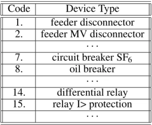
different places in the EPP. Also, the operation fields of these devices have not been taken into account. Such a model represents a device type. In Table 3, a part of device type list is presented.
Code Device Type
1. feeder disconnector 2. feeder MV disconnector
7. circuit breaker SF6
8. oil breaker
14. differential relay 15. relay I> protection
Table 3.Device type list.
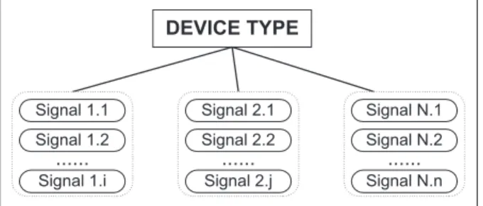
After the device types identification, variables which describe device operation have to be de-fined. In Figure 4 the device type and the variables pertaining to this type are presented. Thevariableis a quantity that may assume any given value by which we can describe the de-vice operation in EPP. At a particular point of time, a value is assigned to the variable and they together make up a signal. The device type is determined by at least one variable, but depend-ing on the operational complexity of the device it can have more than one.
Each variable is defined by at least two values. The device, i. e. the variable cannot be defined by only one variable value, because it means that the device doesn’t change its state. The devices, which do not change or cannot change their state do not have to be controlled. Vari-able valuesare given for the specific variable
Fig. 4.The device type, its variables and variable values.
in operation. By them, the device states are de-fined. The variable can be described by two or more values.
The arranged couple(variable)+(variable
val-ues)]form asignal. Thus, the signal is defined
as a quantity made up of the variable name with values pertaining to it. Schematic presentation of a device type with associated signals is pre-sented in Figure 5. The group of signals repre-sentsa staticset of all possible signals by which operation of the device type is described.
Fig. 5.A schematic presentation of the device type with associated signals.
An example of device types with associated sig-nals is presented in Table 4. The content of the
table is formed as follows:
the first column of the table contains ordinal codes of each device type, which can be used in data processing;
the second column of the table, contains the device type identification;
the third column contains signals formed by variable name and variable values.
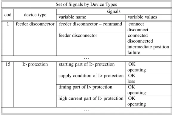
From the list presented in Table 4, it is possi-ble to derivethe set of static signals by device types. An example of such a set of static signals is presented in Figure 6.
Set of Signals by Device Types signals
cod device type variable name variable values 1 feeder disconnector feeder disconnector – command connect
disconnect feeder disconnector connected
disconnected
intermediate position failure
15 I> protection starting part of I> protection OK operating supply condition of I> protection OK
loss timing part of I> protection OK
operating high current part of I> protection OK
operating
Table 4.Device types with associated signals.
By observing Figure 7. we can take into consid-eration the following organized sets of signals:
Set of all process signals by device typesSD
is defined by points of thexyzspace i. e. by expression:
(2)
SD=fσxyzg x=1 2 ::: m
y=1 2 ::: n
z=0 1 ::: r
where σxyz presents the signal defined by
device type, variable and variable values, wheremis the number of device types,nis
Fig. 6.Part of the static signal set.
the number of variables andris the number of variable values of every existing variable. The set of signals ofone device typeis de-fined onyz-plane, i. e. by equation(2), with
x =cons.
The set of signals of one variable is de-fined onxz-plane, i. e. by equation(2), with
y =cons.
The points on the axis parallel with z rep-resent the signals of one variable and one
device type. The subset can also be defined by equation (2), but with x = cons. and
y =cons.
Finally, the subset of points on thexy-plane represent the set of all variables per devices. This variable set, each for itself defines one signal and is presented by equation(2)with
z =cons.
According to circumstances and application of such a model, one can define other characteristic sets of process signals. Comparing equation(2)
and related equations with equation(1)and its
related equations, which are used in describing the device-based and the function-based mod-els, the following may be concluded:
Formally, the structural frame of expressions of particular process signal sets i. e. setsSFT
andSDis entirely analogue.
In essence, SFT and SD sets represent
com-pletely different process signal sets and en-able different approaches to process signal design.
The SFT sets are strictly tied with the
tech-nology of a particular EPP and cannot be directly applied to other EPPs.
Device-based process signal setsSDare
gene-ric (technology-independent) and open
de-signed and they can be universally applied to a great array of EPPs.
Process signals of device-based design rep-resent technology-independent data base of signals which can be easily expanded with new signals.
3.2. Technological Decomposition of an EPP
The first requirement in scope of information modeling is defining a device type model. The model is described in 3.1. The second require-ment is defining an EPP model. That model should allow unambiguous device identification on the base of its location in EPP. In the model, device systematization by location follows tech-nological structure of an EPP.
Because even a small EPP is too complex a sys-tem to embrace its overall operation at once, internal functioning of its subsystems should be described. Therefore, the model construction begins at the level of subsystems. Subsystems
have to be built according to the following prin-ciples:
the borders between subsystems and ways of their interaction at these borders have to be determined;
a subsystem has to be rather simple for the internal operation description;
subsystems mustn’t overlap;
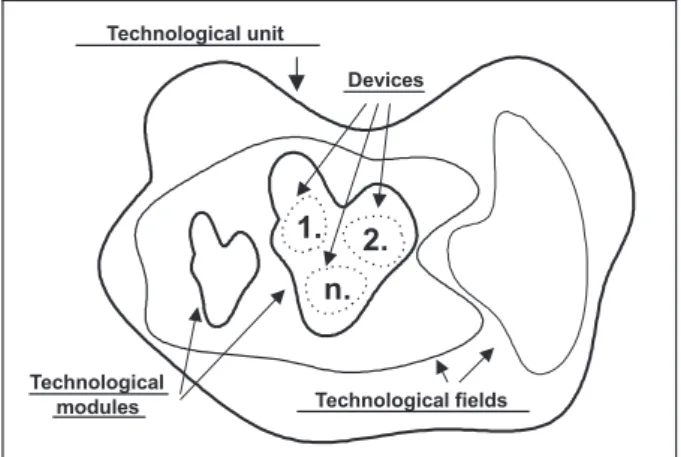
the whole modeled system has to be con-structed by combining all its subsystems. To satisfy the condition that the subsystems mustn’t overlap, we introduce the following concepts: technological unit, technological field, technological modules and technological sub-modules.
Technological unitis a group of devices in the EPP that performs some complex func-tion(command room, engine room).
Technologicalfieldis a part of a technolog-ical unit where voltage levels(400 kV, 220
kV, 110 kV, 35 kV, etc.) are separated.
Technological modules are made by sepa-rating the technological field by lines (220
kV feeder bay Melina,:::). If necessary,
technological submodules can be obtained by further separating the technological mod-ule.
Fig. 8.Tehnological decomposition of an EPP.
Figure 8. illustrates division of one part of an EPP (a technological unit) into technological
technological modules are too narrow, there will be a great number of them, they will overlap and will not function as qualitative EPP model-ing. On the other hand, if chosen technological modules are too wide, then it is possible that the signal will not be precisely defined and located, especially if there are a number of devices of the same type in one technological module. Even-tually, in such a situation we have to create new, smaller submodules within the very technolog-ical module which could enable unambiguous definition of signals.
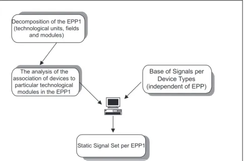
Now, it is possible to explain the procedure for generating a set of static process signals for a particular EPP. The signal set generating pro-cedure is based on the presented information model of EPP and is supported by a computer. First, we have to identify the technological units, fields and modules in the observed EPP. Then, we associate devices with those pertain-ing technological modules. When we associate devices with technological modules, we actu-ally say that technological modules are “filled with devices”. Table 5. presents the principle
how to associate devices to single technological modules.
Because every device has its own type, signals that a device can send(receive) correspond to
the signals of that particular type. The proce-dure for generating a set of static signals per EPP is presented in Figure 9, and the printout of the set of signals per EPP is presented in Table 6.
3.3. Signal Usage Location
After the set of static signals per EPP is gen-erated, signal usage location has to be deter-mined. If we consider, for instance, a hydro-electric power plant as an EPP, the plant would be basically divided into the following techno-logical units: control room, engine room and water power supply. Signal usage locations within a control room would be: control board
(CB), relay board (RB) and auxiliary
switch-board (AS). Signal usage locations in the
en-gine room are: enen-gine board(EB), engine
aux-iliary switchboard (EA), actuator board(AB),
code technological modules associated device(coded)
9 220 kV Feeder Bay Melina 1, 3, 7, 32, 33, 34, 36, 37, 38, 64, 74, 94, 97, 111, 123, 125
Table 5.The principle of association of the devices to technological modules.
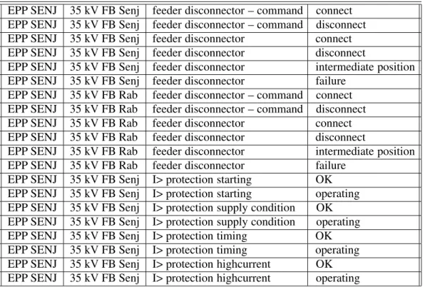
EPP SENJ 35 kV FB Senj feeder disconnector – command connect EPP SENJ 35 kV FB Senj feeder disconnector – command disconnect EPP SENJ 35 kV FB Senj feeder disconnector connect EPP SENJ 35 kV FB Senj feeder disconnector disconnect
EPP SENJ 35 kV FB Senj feeder disconnector intermediate position EPP SENJ 35 kV FB Senj feeder disconnector failure
EPP SENJ 35 kV FB Rab feeder disconnector – command connect EPP SENJ 35 kV FB Rab feeder disconnector – command disconnect EPP SENJ 35 kV FB Rab feeder disconnector connect EPP SENJ 35 kV FB Rab feeder disconnector disconnect
EPP SENJ 35 kV FB Rab feeder disconnector intermediate position EPP SENJ 35 kV FB Rab feeder disconnector failure
EPP SENJ 35 kV FB Senj I> protection starting OK EPP SENJ 35 kV FB Senj I> protection starting operating EPP SENJ 35 kV FB Senj I> protection supply condition OK EPP SENJ 35 kV FB Senj I> protection supply condition operating EPP SENJ 35 kV FB Senj I> protection timing OK EPP SENJ 35 kV FB Senj I> protection timing operating EPP SENJ 35 kV FB Senj I> protection highcurrent OK EPP SENJ 35 kV FB Senj I> protection highcurrent operating
Table 6.Printout of the set of static signals.
and turbine engine splitting(TE). In addition to
these usage locations, we have to point out two remote signal usage locations: Regional Con-trol Center (RC) and National Control Center
(NCC). Table 6 shows EPP signals and their
usage locations. By defining Table 7, we have completed the EPP process signal designing.
At the end, it can be concluded that proposed device-based EPP modeling has to be done in three phases:
the result of the first phase is a generic set of process signals per devices;
the result of the second phase is concrete set of process signals at the EPP level;
in the third phase, usage locations of every single signal should be determined.
EPP Signals EB EA AB TE CB AS RB oth RC NCC
EPP FB Senj 35kV feeder disconnector – state intermediate position + + +
EPP FB Senj 35kV feeder disconnector – state connected + + +
EPP FB Senj 35kV feeder disconnector – state disconnected + + +
EPP FB Senj 35kV feeder disconnector – state failure + + +
EPP Turbine 1 elektrovalve position cooling water operating + + + +
EPP Turbine 1 elektrovalve position cooling water restraint + + + +
EPP Generator 1 DC voltage ok + + +
EPP Generator 1 DC voltage loss + + +
4. The Object-Oriented Characteristics of Device-Based Modeling
In the previous chapter, device-based informa-tion model of the EPP is described. The core of the model are the devices arranged within technological EPP modules. The devices send and receive various signals. Such modeling is based on device abstractions and it can be ap-plied in information modeling of any type of EPP. Functional modeling elaborated in Chap-ter 2 does not offer such flexibility.
In this chapter we want to underline and ex-plain one important characteristic of device-based modeling: modeling based on the de-vices in the very essence represents an object oriented view of the EPP, i. e. its parts. The following describes how to supplement device-based model described in the previous chap-ter so as to become object model. Object-oriented modeling, nowadays, is considered to be a very qualitative and effective approach to system modeling. Moreover, it is supported by many modeling languages and tools. Therefore, our effort to define principles for mapping the device-based model to the object-oriented one is quite comprehensible3],9],11].
4.1. Analogy Between Device-Based and Object-Oriented Model
The object model is based on the following concepts: object, object type, attribute, signal, state, operation, and behavior 1],2],5],10].
Objectis a concrete phenomenon of some ab-straction. It is a basic entity in the object model with good determined borders and identity. The object encapsulates state and behavior. It is also an instance of some type of objects. In an EPP, devices represent sources of information. Some of them are also controllable elements in the EPP and are responsible for some behavior.
Consequently, the most important objects in object-oriented information model of an EPP represent abstractions of real devices. These objects represent abstractions of technical de-vices actually placed in an EPP.
Object identity can be defined by its location in the EPP and following the technological de-composition described in 3.2. (Figure 8.). For
example, object identifier which represents ab-straction of feeder disconnector(FD)connected
with 110 kV busbar number 1 in feeder bay Melina of the hydro-electric power plant Senj, has the structure:HESenj.110kV.FBMelina.FD1.
Generally, a device-representing object in EPP has the identifier of the structure:
EPP.VoltageLevelID.TechnologicalModulesID. DeviceID.
In a definite moment of time an object is in a cer-tainstate. During all its existence the object sat-isfies some conditions (feeder disconnector is
connected)performs some activity(feeder
dis-connector is being connected)or expects some
event(feeder disconnector has just received the
signal Disconnect). The object state is defined
by momentary value of its state variables i. e.
attributes. The object state depends also on the state of some other object if the connec-tion between them exists. In the EPP, there is very often an association between disconnector and circuit breaker. Accordingly, apart from its basic states: Connected, Disconnected and In-termediate positionand depending on the state of associated breaker, the disconnector can also be in the stateBlocked. For example, a simple abstraction of the device feeder disconnector can result in an object typeFeeder Disconnec-tor with one attribute: Position. The attribute can assume discrete values: Connected, Dis-connectedandIntermediate.
Apart form being in some state, an object is responsible for certain behavior. Behavior of the object is everything that can be registered and is a result of some event (signal, elapse
of time, change of state or ademandfor a cer-tainoperation).Operationrepresents a service
incorporated into the object. This service can be required form the object of some specific type by which a specific behavior is provoked. For example, we can require connection of the objects of theFeeder Disconnectortype by re-questing the operation Connect().
In object-oriented model representing some EPP, the most frequent events are the object state change and signal appearance. The appearance
(sending) of the signal is therefore a sort of
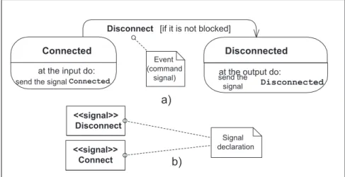
Fig. 10. Part of the state diagram of theFeeder Disconnector type.
Feeder Disconnector type can receive the sig-nal Disconnectfrom the controlling object. A controlling object is an abstraction of one part of the system to control the EPP. This signal will provoke state change of the feeder discon-nector if it is in the state Connected. Having changed from the state Connected into Discon-nected, the feeder disconnector will send the state change information signal to the control-ling object. This behavior can be illustrated by state diagram (Figure 10.a). In an
object-oriented model, even the signal is treated as the object, the instance from the definite signal type
(see Figure 10.b)which is mutually exchanged
between object couple sender – receiver.
The concept objecttype represents a set of the same sort of objects which share the same at-tributes, operationsand associations with other objects.
Finally, analogy between the concepts of the device-based and object-oriented models of an EPP is illustrated in Table 8.
4.2. Object-Oriented Modeling Strategy
Basic steps toward object-oriented EPP model-ing are presented in Figure 11. The first step "finding of types and objects" is undertaken to identify objects as technical device abstractions which preserve their characteristics of technical devices as such, regardless of their function in the EPP, but with regard to information and pro-cess characteristics by which the EPP operation is described.
The second step is undertaken to identify struc-tures of the types: generalization – specializa-tion(G – S)Figure 12.a)and the type: whole –
part(W – P), Figure 12.b).
Defining relevant attributes means identifica-tion of and giving names to relevant character-istics of devices. Attribute values depend on its type. Attribute type in the model is specified
Device-based modeling concepts Object-oriented modeling concepts
device object
device type type
variable attribute
variable values attribute values
signal per device signal
signal per EPP signal
device state object state
command operation
signal usage location signal receiver(object)
Fig. 11.Object-oriented EPP modeling strategy.
by some standard notation system. Relevant operations are the services offered by an object to its environment. The focus is here on exter-nal methods perceptible to surrounding object in the system. External operations represent signal specifications which can be directed to the respective objects. For example, an object of the typeFeeder Disconnectorcan receive the following signals:
HESenj.110kV.FBMelina.FD1.Connect
HESenj.110kV.FBMelina.FD1.Disconnect
State change signals transmitted to controlling objects after the change of state, can be speci-fied in the context of the state diagram elabo-rated for each object type separately. In Figure 10.a)only a part of the state diagram of the class
Feeder Disconnectoris shown. Complete state diagram should specify the minimum of three state change signals:
HESenj.110kV.FBMelina.FD1.Connected
HESenj.110kV.FBMelina.FD1.Disconnected
HESenj.110kV.FBMelina.FD1. IntermediatePo-sition
The examples elaborated in this chapter have il-lustrated the most important aspects relevant for relating the object modeling to the device-based EPP process signal modeling strategy.
5. Conclusion
Efficient and high-quality designing of the EPP automation and control systems was a real chal-lenge during the nineties and has been ever since. The problem of process signal base spec-ification is a significant design problem which can be resolved by using adequate information modeling technique. An efficient approach to the EPP information modeling can significantly
improve the process of automation and devel-opment of the control system design.
Proposed device-based process signal model-ing offers a modular solution which enables ef-ficient, rational and open possibility to orga-nize a process signal base. The previously used functional design has some specific limitations, because a model can be defined only for one EPP and it cannot modularly and openly de-scribe a larger system with more than one EPP. The device is not separated as an information bearing unit and device states cannot be de-fined for the needs of modern process signals design. Redundancy of the data entry is sig-nificant. The device-based design of a process signal base is, on the contrary, modular and open for describing a large number of EPPs, which is based on unique process signal base and it can be efficiently supplemented accordingly to the changes of primary process equipment. It is based on the device as the main information bearing and organizational unit. Besides the modularity, it can also be very easily mapped into the modern object- oriented model. The strength of object-models opens entirely new possibilities for EPP information modeling as well as for improving automation and control system design process.
Therefore, focus of the study will be on the further improvement of the described object-oriented modeling and also on development of a tool for both EPP modeling and automatic process signal sets generating.
References
1] G. BOOCH,ET AL.,The Unified Modeling Language
User Guide, Addison-Wesley publishing company, Santa Clara, California, USA, 1998.
2] G. BOOCH, Object – oriented analysis and
de-sign with applications, Addison-Wesley publishing company, Santa Clara, California, USA, 1997.
3] M. RANDIC, ET AL., Information Modeling of
Power Substations by Using Modeling Language, 10th Mediterranean Electrotechnical Conference MELEKON 2000, Lemesos, Cyprus, 2000.
4] J. SIMUNIC, ET AL., Object-oriented Approach to
Analysis in Power Substation Control,PSAC Sym-posium, Bled, Slovenia, October 1997.
5] J. RUMBAUGH, ET AL., Object-Oriented Modeling
and Design, Prentice-Hall, Inc., New Jersey, 1991.
6] J. SIMUNIC, Z. DUROVIC, Basic Design of Process
Information Flow in Electric Power Substation,
Korema, 37–39, Opatija, 1996.
7] J. SIMUNIC, MSSI – Modular Structure of
stochas-tic Process Information for Power System Control,
CIT,4(3),(1978), 279–290.
8] J. SIMUNIC, Electric Power System Analysis
Us-ing Modular Information Structure,Energija,1–2,
(1994), 39–51
9] J. SIMUNIC, ET AL., Object-oriented Information
Modeling of Power Substations, Daaam, 22–24th October, Cluj – Napoca, Romania, 1998.
10] B. F. WEBSTER, Pitfals of Object-Oriented
Devel-opment, M&T Books, New York, 1995.
Received:May, 1999
Revised:November, 2000
Accepted:February, 2001
Contact address:
Marijana Zivic Young assistant Technical faculty University of Rijeka Vukovarska 58 51000 Rijeka Croatia Phone:+385 51 651438
Fax:+385 51 675818
e-mail:[email protected]
JURAJSIMUNICis Assistant Professor at the Technical Faculty, Univer-sity of Rijeka. For seventeen years he has been working for “Hrvatska elektroprivreda” as an expert in planning, operation and control of power system. He concentrates on modeling of stochastic process information flow in power systems. This was the subject of his doctoral thesis upon which he received his Ph. D. in 1991. from the Faculty of Electrical Engineering and Computing, University of Zagreb.
MIRKORANDIC´ was born in Croatia in 1962. He received the M. S. and Ph. D. degrees(both in Electrical Engineering)from the Faculty of
electrical engineering and Computing, University of Zagreb. Currently he is Assistant at the same faculty(Department of Electrical
Fundamen-tals and Measurement). His research interests include object-oriented
modeling, formal specification techniques and ORB-centric software modeling.