Online Motion Planning for Humanoid Robot Based on Embedded
Vision System
Qiubo Zhong, Qishu Pan, Bingrong Hong, Baofu Fang and Songhao Piao
School of Computer Science and Technology, Harbin Institute of Technology, Harbin, 150001, China E-mail: [email protected]
Keywords:humanoid robot, motion planning, embedded vision, look-up table, image recognition, hierarchical control
Received:March 29, 2010
In this paper, we present a control system based on embedded system according to the features of humanoid robot. First, the image captured by the vision system is recognized through the improved look-up table method. And then with a smooth gait planning of turning motion for humanoid robot presented, the next several motions for the robot can be proposed by the local motion planner based on the minimum of energy dissipation. After that, a control decision is made for the humanoid robot to plan the motions by the method of gait generation off-line and adjustment on-line according to the rules of marathon held in FIRA. In this way, simulations for image processing and experiments on real humanoid robot HIT-2 are present.
Povzetek: Predstavljen je sprotni sistem za načrtovanje gibanja humanoidnih robotov.
1
Introduction
With the development of technology, Omnidirectional locomotion is not restricted to wheeled vehicles. Spenneberg and Kirchner developed omnidirectional locomotion on the robot with eight legs[1]. Hengst et al.. described an approach to generate omnidirectional walking for the Sony ERS-110 Aibo dogs[2]. Behnke planned the gait using walking direction, walking speed and rotational speed and he has tested the proposed approach on humanoid robot Jupp[3]. A gross motion planner utilizing graphics hardware has been proposed to generate humanoid body motion on a flat ground in real time[4].
Recently, FIRA (The Federation of International Robot-soccer Association) is paying more attention to humanoid robot competitions. In the events of humanoid robot, the basic event is the heptathlon such as marathon, sprint, weight lifting, basket ball, lift and carry, obstacle race, penalty. During the process of these events, only vision can be used for the object recognition. Hong presented a fast and effective visual tracking and location prediction algorithm for cooperative multiple soccer robots playing a soccer game. The picture image is captured by the system and the image is selected as a template and 2D color image pattern is extracted from the incoming image[5]. Kuo proposed a middle size soccer robot based on intelligent vision fusion sensing architecture. The proposed autonomous soccer robot consists of the mechanical platform, motion control module and omni-directional vision module[6]. Lu [7] used an omnidirectional vision system to provide middle-size robot with a tracking capability for dealing with the image process control. The panoramic image is installed by matching the convex mirror and CCD lens. The experimental works are conducted to illustrate the effectiveness of the neural fuzzy system on the image
color recognition and tracking the ball. Zhang [8] presented a method of color image segmentation based on multi-valued characteristic. A superset of the objective sample is constructed in color space, and multi-valued characteristic function is employed to describe objective clustering, which ultimately implement the division of color image. Experiments show this algorithm is preferable in both functionality and speed of image processing.
In the field of Robotics, recognition of a working environment using a vision system is critical for an autonomous vehicle. Kim [9] presented a robotic wielding system for closed block assembly. A three dimensional laser vision system is developed based on the optical triangulation technology in order to provide robots with work environmental map. The algorithm architecture for the welding environment recognition is divided into two parts. The first one is the conventional 3D scanning module, and the second one is the plane generation module utilizing a Hough transform. Suzuki [10] presented a corridor recognition method using unprocessed gray-scale image, termed here as a raw-image, and a genetic algorithm, without any image information conversion, so as to perform the recognition process in real-time.
control of forward and backward walking by connecting motion patterns generated in advance. Kajita et al. [12] realized generation of online walking pattern applying Three-Dimensional Linear Inverted Pendulum Mode to humanoid type robot. Lim et al. [13] proposed “quasi-real-time” walking pattern generation using FFT based dynamically stable motion construction method online.
In this paper, we design a system based on embedded vision for humanoid robot, and present an improved looking-up table algorithm for image recognition. Meanwhile, motion of turning for robot is planned and smoothed. A trajectory of the next steps for robot is generated by the local planner and finally, according to the rules of marathon for humanoid robot in FIRA, a decision is made and experiments on real humanoid robot HIT-2 are shown.
2
Design of embedded vision system
and image recognition
2.1
Structure of vision system
The entire system adopts principle of hierarchical control and gets the image by the single camera. The information of image is processed in the PDA (Personal Digital Assistant) and the decision system which is also running in the PDA will get the information and other feedback from sensors and then call the motion system executing. The framework of embedded system is described as shown in figure 1.
Figure 1: Picture of framework of embedded vision system.
In Figure 1, the camera named Logitech Pro 5000 is worked as the image sensor, it captures the image for recognition. The PDA gets the image from camera and executes the image recognition. It also runs the decision for motion and gives the orders for motion control system. Motors and others sensors such as tilt sensor are controlled by motion control system. Information exchanges between the PDA and motion control system.
2.2
Clustering based on improved variable
thresholds seed fill algorithm
In RGB color space, since the values of R, G, B have a strong correlation, RGB color space is not suitable directly as image processing.
HSI color space is widely used in machine vision research areas [14]. Where HSI respectively represents Hue, Saturation and Intensity. RGB to HSI conversion formulas [15] is a non-linear reversible.
a rc ta n '( 3 ( - ), 2 - - )
3
m in ( , , ) 1
-H G B R G B
R G B
I
R G B S
I
(1)
( ) 1.0 -255
sat
aI
Th I (2)
By equation (1) we can get that the value of hue H is
ranged from [0,2π]; Saturation S represents the depth or
purity of a color, whose range is [0,1]. I, the general range of intensity I is [0,255]. In the case of S = 0, the value of I is growing from 0 and the color is from black to white varying in gray-degree. With the value of saturation S, influence on that pixel by value of hue and intensity can be obtained. By equation (2), we also can get that when the value of s is bigger thanThsat( )I , the value of H is going to be as the main feature of that pixel
and vise verse is the value of I, whereais an empirical
value.
Clustering method commonly used requires repeated image scanning, which can not meet the real-time requirement based on the embedded vision system. Seed fill algorithm is commonly used in a class of interactive graphics filling algorithm. It can generate all the clustering just scanning the image for once. The most advantages of this algorithm are fast and the ability of filling the region with variable complex boundary.
If the light is uniform and the color of object is purity, the application of this method can be a very good effective recognition. However, if the light is not uniform, the effect of recognition will be worse. Although adjusting the threshold of hue can improve the effect of recognition under this bad situation, if the threshold of hue is changed to lower, only partly object can be recognized or even misrecognition. Vice verse, if the threshold is higher, interference color blocks is going to affect the accuracy of recognition. Therefore, an improved clustering seed fill algorithm based on variable threshold is proposed. In the robot game, target objects are solid. When the algorithm scans the initial pixel of
image, lower threshold of hue Thl is adopt and when
clustering starts, higher threshold of hue Thh is used.
The numbers of pixels belonging to lower and higher threshold of object are recorded, and the value
described in equation (3) is used to filter theinterference region. If the value
is lower, this meansif the value
is higher, this will bring to the higherprobability of the object. The value
can be gottenthrough experiments described in table 1 bellow.
, ;
Numbers Numbers Thl
Thl Thh
Thh N
N Thl N Thh
N
(3)
Table 1: The lower bound table of filter algorithm
2.3
Recognition of the colour space based
on improved Look-up table
Suppose the visual system needs to identify the N kinds of different colors, and each kind of color represented byCOLORi is corresponding to an interval of HSI,
which represented as
HMIN HMAXi, i , SMIN SMAXi i , IMIN IMAXi, i
, this equals a ‘box’ with its length, width and height are
, ,
i i i
H S I
. Where Hi HMAX HMINi- i ,
-i i i
S SMAX SMIN
, Ii IMAXi -IMINi. N kinds
of colors are corresponding to N ‘box’. Clustering of pixels based on color is to judge whether the coordination of every pixel in the color space is just in
some ‘box’. For instance, if a pixel represented asPiis in
the BOXi , Pi belongs COLORi .Commonly used
method of clustering is to compare value of H, S, I for each pixel with N kinds of color corresponding to the HSI interval determining whether in the interval or not. For every pixel, the times of comparison operation for clustering operation need to be N × 6 integer variables. It is inefficient if the same clustering operation to all the pixels of the color images is implemented, which affect the real-time target recognition. In the HSI color space, hue is one of the biggest variable differences among the various objects. Therefore, the equation of hue is unchanging. When the HSI color cone changes along the radial orientation, its saturation of color changes, the color attributes are the same, but a change in purity, which is by the color cone color, in the outer part of the net is bright comparison with close to the center part being impure, and gradually moving gray. In fact, if the purity of an object is relatively high, only lower bound of saturation is considered to filter out variegated instead of defining the upper bound. Therefore, only value of I is considered to define to prevent from judging by mistake.
By this method, only N × 6 integer variables need to be comparison for execution of every pixel.
As we known, using look-up table approach can further speed up the clustering speed. This approach adopts operation of array indexes instead of N×4 times comparison operation, which greatly improves the efficiency of computing for clustering algorithm. However, the disadvantage is its too much storage space. According to this problem, an algorithm based on improved look-up table is present to complete the color space clustering.
The use of projection transformation can project the pixels of image in the color space corresponding to the coordinates onto the three axes of color components respectively. Thus, the number of dimensions of clustering an array of look-up table reduced to one dimension. J kinds of color space can be expressed by three arrays of unsigned integers with j-th bit. (HClass[0…255], SClass[0…255], IClass[0…255]). Where array ‘HClass, SClass and IClass’ represent each value of color respectively. The j-th bit of elements in every array denotes the binarization results of the j-th color. The clustering of pixels is achieved through bitwise AND operation for arrays.
The nature of approach of improved look-up table present in this paper is based on the multi-threshold for color image segmentation. There are two advantages of this approach.
1. By adopting j-th bit of unsigned integers to represent the elements of array, only two times for bitwise AND operation can determine the color category of pixels, which greatly increased the speed.
2. By projecting three-dimensional color space onto a one-dimensional axis, only three one-dimensional arrays can express the color space and predefined color category, which greatly save the memory space.
2.4
Fast goal-find algorithm
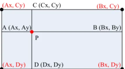
In robot soccer, the goal is horizontally placed, so we can regard the goal as a horizontal rectangle. If the robot is not in the middle of the field, because of the influence of large near far smaller, the goal in the image will be a slight tilted rectangle. Although the goal is tilted, the inclination angle is negligible. In addition, in the current humanoid robot soccer, the ball will not be kicked off the ground. the tilted rectangle will just affect the computation of height, but not affect the computation of width. The goal-finding process is shown in figure 2.
A (Ax, Ay) B (Bx, By)
C (Cx, Cy)
D (Dx, Dy)
(Ax, Cy)
(Ax, Dy)
(Bx, Cy)
(Bx, Dy)
P
Figure 2. The schematic diagram of rectangle detection.
In this figure, p is seed point, from p cast four rays toward left, right, up and down intersect the boundary at Numbers of pixel for
higher threshold
(Ratio of lower threshold)20 0.15
40 0.25
80 0.45
160 0.5
320 0.5
640 0.45
1280 0.4
2560 0.4
5120 0.35
A, B, C, and D. Assume that the coordinate of A is (Ax, Ay), the coordinate of B is (Bx, By), the coordinate of C is (Cx, Cy) and the coordinate of D is (Dx, Dy). Using these four coordinates, we can compute the four coordinates of vertex. The coordinate of upper left vertex is (Ax, Cy), the coordinate of lower left vertex is (Ax, Dy), the coordinate of upper right vertex is (Bx, Cy) and the coordinate of lower right vertex is (Bx, Dy). In order to improve the precision and avoid the noise interference, we can cast numbers of rays towards one direction (such as upward side), get many boundary points, we remove the points whose difference are high and compute the mean of coordinates.
3
Motion planning for humanoid
robot
3.1
Motion planning for turning
Assuming the n-th location for foot
n , n
x y
p p can be
expressed as shown in equation (4)
16
( ) ( 1) ( )
( 1) ( 1) ( )
n n n
x x x
n n n n
y y y
p p s
p p s
(4)
Where ( )n x
s
is the step length on forward direction ofhumanoid robot, and ( )n y
s
is the step length on lateral
direction.n represents the n -th step. When the robot
turns, the parameters of its gaits can be described as
Figure 3.
, 1, 2,3
i l
P x y i
is the location of left of
humanoid while
, 1, 2,3
i r
P x y i
is the location of right. When the robot walks straight, the angle between
left turning foot and the horizontal line Sl(1)should be
changed according to the equation (4).
Figure 3: Sketch map of parameters of turning for humanoid robot
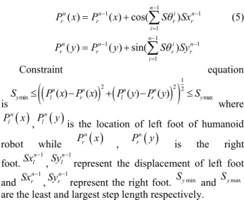
From the figure 3, we can get the equation of parameters of turning gait as shown in equation (5)
1
1 1
1
( ) ( ) cos(n )
n n i n
l l l l
i
P x P x S Sx
1
1 1
1
( ) ( ) sin(n )
n n i n
l l l l
i
P y P y S Sy
1
1 1
1
( ) ( ) cos(n )
n n i n
r r r r
i
P x P x S Sx
(5)1
1 1
1
( ) ( ) sin(n )
n n i n
r r r r
i
P y P y S Sy
Constraint equation
is
1
2 2 2
min ( ) ( ) ( ) ( ) max
n n n n
y l r l r y
S P x P x P y P y S
where
n lP x , n
l
P y is the location of left foot of humanoid
robot while P xrn
, P yrn
is the rightfoot.Sxln1,Syln1represent the displacement of left foot
and Sxrn1,Syrn1represent the right foot. Symin and Symax
are the least and largest step length respectively.
3.2
Smoothing for the complex gaits
The connection of complex gaits is a question worth studying. If the connection failed, the completely complex gaits may fail. To smooth the connection
between two gaits, suppose the ias the degree of joint in
timei, so the next degree of joint is i1. If the
i
ispassed and the time i1 is coming, so the current degree
of joint is i1, and the next degree of joint is i2. For
the smoothly connecting from itoi1, we adopt the
trigonometric function to time difference. Suppose the
beginning time is Ti and the ending time is Ti1, the
transition angle
t and be obtained from thefollowing equations:
11
sin 2
i i i
i i i t T t T T
(6)
And the angular velocity can be get by equation (7):
11 1
cos 2
i i i
i i i i
t T t
T T T T
(7)
Since the
t is derivable between Ti and Ti1, theconnection curve is smoothing.
3.3
Local motion planner
We must evaluate the reference trajectory to search for the best one. The reference trajectory, which needs lower energy is better. We give the evaluation function
involved the average power Pav , average deviation
powerDav and average torquePL.
The average power is a key factor for power analysis of motion. Supposing the torques not doing negative work, and absolute value of power is obtained in every
moment. The average power Pav with the model of
HIT-2 can be obtained by equation (8) as follows:
2 6 , , 0 1 1 1 Tav i j i j
i j
P t t dt
T
(8)Where is the torque of motor, is the angular velocity
Although the Pav is the key factor for optimizing the
energy consumed by the robot, during the process of motion, there is a situation that the instantaneous power is approaching infinity, however, the average power may be little. This instantaneous power may damage to the system under some situations. Therefore, according to this situation, another factor to evaluate to the consumed energy should be built, which is the average deviation
power Dav . The Dav can be achieved by following
equation (9) and (10):
2 6 ,
,
1 1
i i j i j
i j
P t t t
(9)
2 01 T
av i av
D P t P dt
T
(10)Where Piis the instantaneous power of robot.
The average torque PL can be get from equation (11):
2 6 2
, 0 1 1
1 T
L i j
i j
P t dt
T
(11)Therefore, the total energy consumed equation can be described as followed:
min min min
min av av L
E P D P (12)
Global scanning an unknown environment using vision will take considerable time, and motion planning for humanoid robot under unknown environment is a complex project. Therefore, we design a local motion planner, which can be defined as finding a feasible
locomotion for the next nsteps based on minimum of
energy dissipation using equation (12). We design some basic motions off-line including of forward one-step, backward one-step, left one-step, right one-step, turn right and turn left. These motions, which stored in the motion library of robot are test on the flat floor and executed stably. The local motion planner can use these basic motions for planning the locomotion.
The local motion planner plans the local locomotion via the information of itself and captured by the vision
system. A sequence M M M
1, 2,Mn
composed ofbasic motions can be gotten according to the trajectory. Let M k t di
, , , , e
denote the basic motion, wherekisthe number of motion, trepresents the time needed to
finish the motion, dis the distance from the projection of
centre of gravity of robot under the former pose to the
next pose after finishing this motion, denotes the
shifting angle between the former pose of robot to the
next pose completed by this motion, and the e means the
energy consuming during this motion, which is test by the experiments. The planner can generate a feasible trajectory according to the principle of least energy consumption. First, the planner installs the whole
motions Mi and computes the distance from initial
location qinit and goal locationqgoal . Then, selects the
motion by random and execute motion. If theqgoalequals
the qrobtained from executing the motion, then return a
feasible sequence, else goes back to select another motion. The pseudocode of planning algorithm is described as follows:
Step 1. Install Miin M, Dgoal Compute q
goal,qinit
Step 2. SelectMr Rand M M q
r,
; r Exec M
rStep 3. Dgr Compute q
goal,qr
Step 4. IF Dgr Dgoalthen
Step 5. Dgoal Dgoald Er, E er,Goto Step 5
Step 6. else Goto Step 2 Step 7. IF
qr qgoal
thenStep 8. Return a feasible sequence of Mqr
Step 9. else Goto Step 2
The algorithm described above can generate several feasible sequences of motions. The minimum energy consuming of sequence will be selected to execute. Since we select the basic motion in the library by random, the computational complexity will increase exponentially by the increase of basic motions. The local planner just plans the two or three steps next to robot in order to eliminate the time of computing.
When the robot executes the sequence of motions, the information gathered by the vision system and information gained by the tilt sensor can help the robot to adjust its location and keep stable.
The strategy program structure diagram of
controlling the motion of robot can be described as in figure 4.
the time consumed on foot planning in real-time matches can be greatly saved. Moreover, in this paper, smooth gait planning takes the place of left-right motion, which saves time in the walking process and ensures that the robot can finish the match in a shortest time to get a better result.
3.4
Control decision for marathon
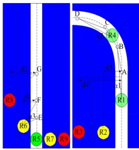
The aim of marathon held in FIRA is to test the robustness and endurance of humanoid robots. The task is for the robot to track a visible line as quickly as possible. The rules of marathon are that a robot is not allowed to leave the track. A robot is considered to have left the track if the distance between the current position of the robot and the closest point on the centre line to that position is more than 50cm. According to these rules, we have made the decision as follows. The Figure 4 has shown the schematic diagram of control strategy for marathon. Where A, B, C, D, E, F, G are the locations of robot may occur, and d1, d2, d3, d4 mean the vertical
distances between the robot to centre of visual line. α1,
α2, α3 are the angles between the robot and next two
locations.
As shown in Figure 5, the white line is visible for the robot to track. The left of the picture is a straight line while the right is a curve. The robot should walk forward by tracking the line and not be far away from the line. The locations of green circles in the figure 3, which marked R1, R4 and R5, are the ideal for the robot to walk and the red circles, which marked R3, R8 and R9, are not allowed for the rule and should do some adjustments to get close to the visible line. When the locations of robot become yellow circles, which marked R2, R6 and R7 should get some warnings.
With the feedback of vision, the robot can adjust the location online by using the basic motion.
Figure 5: Schematic diagram of control strategy for marathon held in FIRA
The decision is made following according to the rule of marathon:
Step 1. Initialize the vision system and start the robot;
Step 2. Execute the basic motions generated by the local planner according to the information from vision system;
Step 3. If the distance d between the center of visible line and the projection of center of gravity of robot is more than 50cm, go to Step 5;
Step 4. If the visible line is a curve with the judgment of
α, go to Step 6;
Step 5. The robot runs a turning for left or right motion according the shift distance. Go to Step 7;
Step 6. The robot adopts the curve motion planning and go to Step 3;
Step 7. Forward motion is executed by the robot; Step 8. If the robot touches the finishing line, stop
motion is arrived, else go to Step 2
4
Simulations and experiments
The images captured by the vision system are under processing by the method present this paper, which can be finished in a short time. The visible lines included straight and curve are shown in Figure 6 and the results of processing is also shown in the bellow of this figure, where we can conclude that the lines can be easily recognized by the vision system. The color space selected in this paper is HSI, where H means Hue, S means Saturation and the I represents Intensity. The simulation results based on HSI color space are shown in Figure 7. Where (a) and (b) are the H value, (c) and (d) are the S value while (e) and (f) are the I value of line and curve respectively. From the (b) of Figure 5, for instance, vertical axis is the number of pixels corresponding on the Hue value of horizontal axis, and most values of Hue are in the interval of [140,150], therefore, we select 145 for the value of Hue. Experiments for running along the circle are achieved on real humanoid robot HIT-2 and the snapshots of the experiments are shown in Figure 8.
(a) (b)
(c) (d)
(e) (f)
Figure 7: Pictures of results of simulation based on HIS
From the Figure 7, we can know the H value and S value are more concentrated in dealing with recognition of curve than line. And the I value is better in recognition of line than curve.
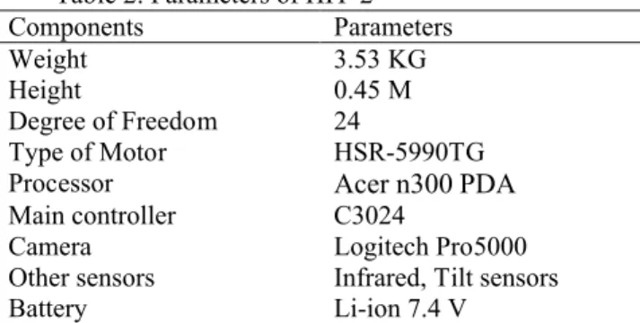
The experiments are implemented on real humanoid robot HIT-2. The parameters of HIT-2 are list in table 2.
Table 2: Parameters of HIT-2
Components Parameters
Weight 3.53 KG
Height 0.45 M
Degree of Freedom 24
Type of Motor HSR-5990TG
Processor Acer n300 PDA
Main controller C3024
Camera Logitech Pro5000
Other sensors Infrared, Tilt sensors
Battery Li-ion 7.4 V
It takes 1 minute and 2 seconds to finish the circle lengthened 6.2 meters. Eight snapshots of every 7
seconds of video are shown respectively, where picture 1, 2 and 6 are the motions of walking straight while picture 3, 4, 5, 7 and 8 denote the motions of walking on curve. All the pictures have shown that the robot can walk along the visual line successfully and quickly.
5
Conclusion
Sports and entertainment humanoid robot has always been the strong development in FIRA, and the key technology of humanoid robots has been applied and developed during the races. In this paper, we designed a humanoid robot based on vision system according to the characters of marathon in FIRA. The information of feedback of vision system could be adopted as the chief sensor information for the decision system. Motion planning for the local environment was achieved by the local motion planner and the decision was made for the marathon.
Using the method present in this paper, it can speed up the process of motion planning during the match. Turing motion is obviously faster than the normal turn left or right motion because it reduces the time consumed for feedback of signal and the balance of robot.
In the future, motion planning in complex environment should be considered and the complex motions for humanoid robot such as step on or step over obstacles will be designed.
Acknowledgement
This project is supported by the National Natural Science Foundation of China with grant number 61075077
References
[1] Spenneberg D. and Kirchner F., 2000.
Omnidirectional walking in an eight legged robot.
In: Proceedings of the 2nd International
Symposium on Robotics and Automation(ISRA), pp: 108-114.
[2] Hengst B., Ibbotson D., Pham S. B., and Sammut
C., 2002. Omnidirectional locomotion for
quadruped robots. In: RoboCup 2001: Robot Soccer World Cup V. Springer, 22: 368–373.
[3] Behnke S., 2006. Online trajectory generation for omni directional biped walking. In: Proceedings of the 2006 IEEE international conference on robotics and automation, Orlando, Florida, May, 2006. pp: 1597-1603.
[4] Kuffner J., 1998. Goal-Directed navigation for animated characters using real-time path planning and control. In: Proceedings of CAPTECH’98 Workshop on Modeling and Motion capture Techniques for Virtual Environments, Springer-Verlag, 1998.
[5] Hong C. S., Chun S. M., Lee. J. S., Hong K. S., 1997. A vision-guided object tracking and prediction algorithm for soccer robots, In: Proceeding of the 1997 IEEE International Conference on Robotics and Automation. Albuquerque, NM. 1997, pp: 346-351.
[6] Kuo C. H., Yang C. M. and Yang F. C.,2005. Development of intelligent vision fusion based autonomous soccer robot. In 2005 IEEE International Conference on Mechatronics. July 2005.pp:124-129
[7] Lu H. C., Tsai C. H., 2006. Image Recognition Study via the Neural Fuzzy System. In: Proceeding of International Conference on Intelligent Engineering Systems, London, 2006. pp: 222-226. [8] Zhang J.L., Li S. Q., 2010. Color Image
Segmentation Bsed on Multi-valued Eigenfunction. In: Proceeding of the 2010 2nd international Workshop on Intelligent Systems and Application. Wuhan, China. 2010. pp:1-4
[9] Kim M. Y., Ko K. W., Cho H. S., Kim J. H., 2000. Visual sensing and recognition of welding environment for intelligent shipyard welding robots. In: Proceeding of the 2000 IEEE/RSJ International Conference on Intelligent Robots and Systems, Takamatsu, 2000. pp: 2159-2165.
[10] Suzuki H. and Minami M., 2002. Real-time corridor recognition adaptable for shadow and illuminance variation. In: Proceeding of the IEEE 5th
International Conference on Intelligent
Transportation Systems, 2002. pp: 61-66
[11] Setiawan S. A., Hyon S. H., Yamaguchi J., and Takanishi A.,1999. Physical interaction between human and a bipedal humanoid robot realization of human-follow walking. In: Proceeding of the 1997
IEEE International Conference on Robotics and Automation, 1999. pp: 361–367.
[12] Kajita S., Matsumoto O., and Saigo M., 2001. Real-time 3D walking pattern generation for a biped robot with telescopic legs. In: Proceeding of the 2001 IEEE International Conference on Robotics and Automation, 2001.pp:2299–2306.
[13] Lim H., Kaneshima Y. and Takanishi A., 2002. Online walking pattern generation for biped humanoid robot with trunk. In: Proceeding of IEEE International Conference on Robotics and Automation, 2002. pp: 3111–3116.
[14] Manjunath B. S., Ohm J. R. and Vasudevan V. V., 2001. Color and Texture Descriptors. In: IEEE Transactions on circuits and systems for video technology, Vol. 6, pp. 703-715, 2001.
[15] Stockman G. and Shapiro L., 2001. Computer Vision, Prentice-Hall, 2001.
[16] Kajita S. and Hirukawa H., 2005. Humanoid robots.. In: Ohm-sha, Ltd. 2005. pp: 120-130. [17] James J. Kuffner, Satoshi Kagami, Koichi
![Figure 4: The strategy program structure diagram Compared to normal dynamic foot planning for humanoid robot [17], the elapsed time in the motion planning presented in this paper is minor](https://thumb-us.123doks.com/thumbv2/123dok_us/8043660.2129910/5.892.461.817.682.985/strategy-structure-compared-planning-humanoid-elapsed-planning-presented.webp)