Pi Based Power Quality Enhancement Of Grid Connected Wind
Energy System For Dc
–
Link Energy Storage System
K.Janamma1,K.Sudheer2,M.Balasubbareddy3
1PG Scholar,2Assoc. Prof.,3Prof.& HOD
Prakasam Engineering College ,Dept. Of EEE, JNTUK,India,
1 [email protected],2 [email protected],3, [email protected]
Abstract
The power quality of the inter connected grid is much effected due to the interconnection of non renewable energy sources like wind and solar systems. The drastic changes in their input effectively change the grid parameters. This paper provides a novel method for power quality improvement of Grid connected wind energy system in which static compensator continuously monitors the line parameters like harmonics and reactive power .This paper utilizes the capabilities of PI tuned - hysteresis Controlling along with the energy storage system at the dc link. Finally using MATLAB/SIMULINK tool, at the grid point of common connecting line, power factor and Total Harmonic Distortions are much improved.
Key words:Wind Energy System, Dc Link Energy Storage System, Pi Controller
1.Introduction:
The increasing number of renewable energy sources and distributed generator requires a new strategy for operation and management of electric grid system. Today, wind energy generating system is connected into the power system to meet the consumers demand and to support the grid. However, the output power of wind generator is fluctuating and will affect operation of interconnected grid. The utility system cannot accept the new generation without the strict condition of voltage regulation due to real power fluctuation and reactive power generation/absorption. Thus addition of wind power into the grid system, affects the power quality. However, in practice the wide use of a nonlinear load connected to
power distribution system or inverter based application, causes significant power
quality degradation in the grid connected system in the terms of current/voltage harmonic, power factor
and resonance problem. As a result of a nonlinear nature of the load, the purity of waveform of supplies may lose. Thus the power quality issue is becoming an increasingly important to the electricity consumer at all level of usages [1]. The impact of the wind generation on the power system will no longer be negligible if high penetration levels are going to be reached. At high penetration level there is need for additional voltage management in the grid. The penetration of wind generation into the power system will increased due to the use of variable speed wind generation to accommodate the maximum power in the power system. In variable speed induction generator system with grid connected power converter are increasingly used. The use of power converter system is now becoming a power conditioning system, such as to adjustability of voltage and reactive power and the control of supply of active power. These technical capabilities of wind generating system can be used in recent development in power control technology [5]-[7].
The proposed control system with energy storage has the following objectives:
Unity power factor at the point of common coupling line (PCC).
Reactive power support from wind generator and batteries to the load. Stand-alone operation during grid is
failure .
THD% is improved
2. System Description:
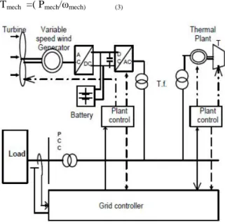
The wind generating system is connected with turbine, induction generator, and AC-DC-AC converter, interfacing transformer. The static characteristic of wind turbine can be described by the relationship between total power in the wind and mechanical power of wind turbine as in equation (1).
Pwind= ρπR2V3wind (1)
where ρ- air density (1.225 Kg/ m3) , R is rotor radius in meters, Vwind is the wind speed in m/sec. CP IS the power coefficient.
This coefficient can be expressed as a function of tip speed ratio λ and pitch angle θ. Themechanical power can be written as (2).
Pmech= CPPwind
Pmech= ρπR2V3windCP (2)
By using the turbine rotational speed, ω turbine mechanical-torque is shown in (3)
Tmech =( Pmech/ωmech) (3)
Fig .1 grid connected wind energy system
In the inverter, the capacitor is used as the intermediate elements, which decouples the wind generating system and battery storage as shown in Fig. 2 and modeled with (4).
C Vdc=Idc(rect)–Idc(inv) (4)
where C is circuit capacitance, Vdc is rectifier voltage, Idc(rect) is rectified dc-side current, Idc(inv) is inverter dc-side current.
The battery storage is connected to dc link and is represented by a voltage source Eb connected in series with an internal resistance Rb. The internal voltage varies with the charge status of the battery. The terminal voltage Vdc is given in (5).
Vdc=Eb+Ib*Rb (5)
where I b represent the battery current. It is necessary to keep adequate dc link level to meet the inverter voltage as in equation (6).
Vdc≥ Vinv (6)
where Vinv is line-to-neutral rms voltage of inverter (230Vrms), Switching frequency - 2Khz, Inverter output frequency-50Hz and Ma .is modulation index (0.9).Thus the dc link is design for 800Volt .
Fig. 2. DC Link for battery storage and wind generator.
2.1. POWER QUALITY STANDARDS:
Voltage Variation The voltage variation issue results from the wind velocity and generator torque. The voltage variation is directly related to real and reactive power variations. The voltage variation is commonly classified as under:
• Voltage Sag/Voltage Dips. • Voltage Swells.
• Short Interruptions.
• Long duration voltage variation.
The voltage flicker issue describes dynamic variations in the network caused by wind turbine or by varying loads. Thus the power fluctuation from wind turbine occurs during continuous operation. The amplitude of voltage fluctuation depends on grid strength, network impedance, and phase-angle and power factor of the wind turbines.
Harmonics:
voltage and current should be limited to the acceptable level at the point of wind turbine connection to the network. To ensure the harmonic voltage within limit, each source of harmonic current can allow only a limited contribution, The rapid switching gives a large reduction in lower order harmonic current compared to the line commutated converter, but the output current will have high frequency current and can be easily filter-out.
3.Grid Coordination Rule a)voltage rise:
The voltage rise at the point of common coupling can be approximated as a function of maximum apparent power of the turbine, the grid impedances R and X at the point of common coupling and the phase angle , given in (7)
ΔU = Smax(RCOSφ-Xsinφ)/U 2
(7) where Δuis voltage rise, Smax is apparent power,
is the phase difference, U is the nominal voltage
of grid. The Limiting voltage rise value is 2%
b)voltage dips:
The voltage dips is due to start up of wind turbine and it causes a sudden reduction of voltage. It is the relative % voltage change due to switching operation of wind turbine. The decrease of nominal voltage change is given in (8).
d = Ku (8)
where is relative voltage change, rated apparent power, short circuit apparent power, and sudden voltage reduction factor. The acceptable voltage dips limiting value is3 %.
c)Flicker:
The measurements are made for maximum number of specified switching operation of wind turbine with 10-min period and 2-h period are specified, as given in (9)
P1t =C(ΨK) (9)
Where P1t - Long term flicker. C(ΨK)-Flicker
coefficient calculated from Rayleigh distribution of the wind speed. The Limiting Value for flicker coefficient is about , for average time of 2 h
d) Harmonics:
The harmonic distortion is assessed for variable speed turbine with a electronic power converter at the point of common connection [9]. The total harmonic voltage distortion of voltage is given as in (10):
(10) where is the nth harmonic voltage and is the fundamental frequency (50) Hz. The THD limit for 132 KV is %. THD of current is given as in (11)
ITHD = 100 (11)
Where is the nthharmonic current and is the
fundamental frequency (50) Hz. The THD of current and limit for 132 KV is %.
e)Grid frequency:
The grid frequency in India is specified in the range of 47.5–51.5 Hz, for wind farm connection. The wind farm shall able to withstand change in frequency up to 0.5 Hz/s [9]..
4.praposed grid system configuration:
The STATCOM based current control voltage source inverter injects the current into the grid in such a way that the source current are harmonic free and their phase-angle with respect to
source voltage has a desired value. The injected current will cancel out the reactive part and harmonic part of the load and induction generator current, thus it improves the power factor
and the power quality. To accomplish these goals, the grid voltages are sensed and are synchronized in generating the current command for the inverter. The proposed grid connected system is implemented for power quality improvement at point of common coupling (PCC)
4.1. System Operation:
The shunt connected STATCOM with battery energy storage is connected with the interface of the induction generator and non-linear load at the PCC in the grid system. The STATCOM compensator output is varied according to the controlled strategy, so as to maintain the power quality norms in the grid system. The current control strategy is included in the control scheme that defines the functional operation of the STATCOM compensator in the power system. A single STATCOM using insulated gate bipolar transistor is proposed to have a reactive power support, to the induction generator and to the nonlinear load in the grid system. The main block diagram of the system operational scheme is shown inFig.4.
Fig-4.bolck diagram of system operational scheme 4. 2.Control Scheme:
In the proposed grid connected system, the magnitude of a grid current is determined from reference generated from grid voltage. The battery energy storage system (BESS) is connected in parallel to the dc capacitor. The battery will naturally maintain the dc-capacitor voltage within a small operating range.
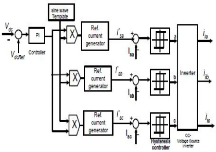
The BESS is the best suited since it rapidly injects or absorbed real power to stabilize the grid system. It also controls the distribution and transmission system in a very fast rate. The control scheme approach is based on injecting the currents into the grid having ‘bang-bang controller’ using a hysteresis current controlled technique. A hysteresis current controller keeps the control systems variable between the boundaries of hysteresis area and gives rise to correct signal for inverter operation. The control system designed for generating the switching signals to the inverter is shown in Fig. 5.
Fig. 5. Control circuit of CC-VSI
4.3. Grid Synchronization:
With a three-phase balance system, the RMS voltage source amplitude is calculated at the sampling frequency from the source phase voltage (VSa ,VSb,VSc ) and is expressed as sample template Vsm , sampled peak voltage, as in (12).
Vsm= {2/3(Vsa2+Vsb2+Vsc2)}1/2 (12)
The unit vectors are obtained from AC source voltage and the RMS value of unit vector Usa,Usb,Usc are represented in (13).
Usa= ,Usb= ,Usc= (13)
The in-phase generated reference currents are derived using in-phase unit voltage template as, in (14).
sa*=I.Usa, sb*=I.Usb, sc*=I.Usc (14)
where, I –is proportional constant magnitude of filtered source voltage for respective phases. This ensures that the grid current is controlled to be sinusoidal. This method is simple, robust and favorable as compared with other methods.
4.4. Current Controller:
The bang-bang current controller is to control the current in the inverter. The reference current is generated as in equation (14) and actual current are detected by current sensors and are subtracted for obtaining a current error for a hysteresis based bang-bang controller. Thus the ON/OFF switching signals for IGBT of inverter are derived from hysteresis controller The switching function SA for phase ‘a’ is expressed as (15)
sa > ( sa*-HB) →SA=1 (15)
where - HB is a current band of the controller. Similarly the switching function SB , SC can be derived for phases ‘b’ and ‘c’ respectively [10] -[12].
5. Results And Simulation Of System:
The proposed control scheme is simulated using MATLAB/SIMULINK in power system block set. The system parameter for given system is given in Table I.
TABLE 1
SYSTEM PARAMETERS
Source voltage 3-phase 415v,50HZ
Source ,line inductance
2MH,0.5MH
Wind generator, induction
generator
150kw,415v,50HZ,p=4, avg wind velocity-5m/s
Dc link
parameters
Dc link-800v,C=5μf
Rectifier 3 arm bridge type
Snubber R=100Ω,Ron=0.01Ω ,
C=100 μf
Load parameters 3-phase, 415v, non linear load, R=10 Ω,C=1 μf
5.1. Steady State Performance Of The System:
A non linear load is considered for the simulation of this system. These nonlinear loads in the system will affect and disturb the grid current waveform. To have the grid current in distortion free, the correct amount of current must be injected to cancel out this distortion effect. The performance of the system is observed by operating the controller for the power quality improvement for these loads.
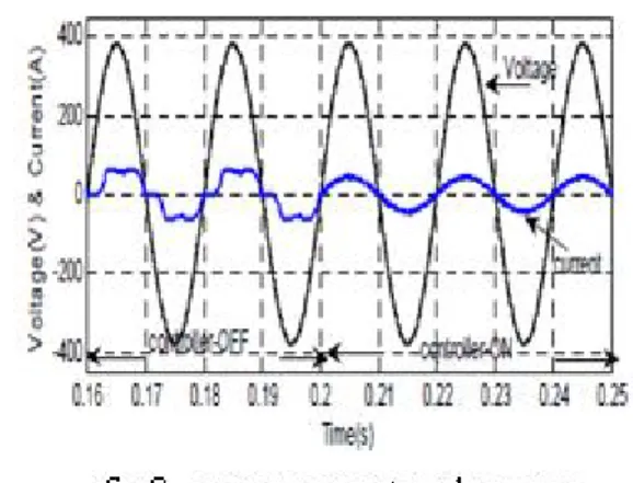
The inverter is switched ‘on’ at 0.2 sec .The grid/source current Is, inverter injected current
Iinv , load current IL are measured with and
without controller operation. The current supplied from the source is made sinusoidal, harmonics-free as soon as controller is in operation and is shown in Fig. 6 (a). The injected current supplied from the inverter is shown in Fig.6 (b). The load current in the system is shown in Fig.6 (c).During this interval the load current will be the addition of source current and inverter current. The PCC
voltage is shown in
Fig.6.(d)
5.2. Dc Link:
The wind energy generator is operated to generate the power and supplied to rectifier to interface in the dc link. The dc link voltage is shown in Fig. 7(a). To transfer the real power from wind generator into the load, the generated power is fed to rectifier for charging the batteries. The battery maintains a constant dc terminal voltage while supplying current on demand. It is propose to decouple the energy storage from the inverter by a separately dc-dc converter. The current through the dc link is shown in Fig.7. (b).
5.3. Unity Power Factor:
5.4. Power Quality At PCC:
The current waveform before and after the inverter operation is analyze for power quality measure. The Fourier analysis of the waveform is expressed without the inverter- in the system and the THD of the source current signal is shown in Fig.9 (a) and the measured THD and its harmonics order is shown in Fig.9(b).
Fig.9.a)source current and fft of source current(before)
b) source current and fft of source current(after
5.5. Performance Under Stand-Alone Mode:
It is observed that the system is operating in power quality mode up to 0.6 sec. The dynamic performance of the system is monitor by operating
the circuit breaker at 0.6 sec. Under such condition system performs as a stand-alone mode. The voltage sensor senses the condition and transfers the switches to generate the reference current in stand-alone reference generator. During this mode the inverter will support the critical load in absence of grid failure. Due to the unavailability of source, the inverter will supply the full load current in this duration. The grid current, load current and inverter current in stand-alone mode is shown in Fig.10.
Fig. 10. a)Grid Current b) Load Current c) Inverter-injected current.
Comparisions:
Parameters Without statcom
PI based statcom Power factor 0.86 1
THD% 9.30% 0.40%
6. Conclusion:
The scheme of variable speed type wind energy conversion scheme with batteries energy storage in grid interfaced is presented. The system has an interface of inverter in current controlled mode for exchange of real and reactive power support to non-linear load. The scheme utilizes power electronic switching device approach.
energy storage and is made available under the steady state condition. This also allows the real power flow during the instantaneous demand of the load. Thus the power quality can be significantly enhanced through the use of inverter interfaced in grid system. The suggested control system is suited for rapid injection or absorption of reactive/real power flow in power system.
The battery energy storage provides rapid response and enhances the performance under the fluctuation of wind turbine output and improves the voltage stability of the system. This scheme is providing a choice to select the most economical real power for the load amongst the available wind– battery-conventional resources. The system always operates within power quality norms also provides stand-alone mode and support the grid
Acknoledgement
I would like to thank my parents for moral support and faculty of EEE department for technical support
References:
[1] Dusan Graovac,Vladimir A.Katic,Alfred Rufer , “Power quality problems compensation with universal power quality conditioning system,”
IEEE Trans. on Power Delivery, vol. 22, no. 2, pp.
968-97, April 2007.
[2] S.W.Mohod, M.V.Aware,“ Power quality issues & its mitigation technique in wind generation, ”Proc. of IEEE Int. Conf.on Harmonics and Quality
of Power (ICHQP) , pp. 1-6, Sept. 2008.
[3] Z. Chen, E. Spooner ,“Grid power quality with variable speed wind turbines”, IEEE Trans. on Energy Conversion, vol.16, no. 2, pp. 148-154,
2008.
[4] J. M. Carrasco, “Power electronic system for grid integration of renewable energy source: a survey,” IEEE Trans. On Industrial Electronics,
vol. 53, no. 4, pp. 1002-1014, 2006.
[5] J.W.Smith and D.L.Brooks, “Voltage impacts of distributed wind generation on rural distribution feeders.” in Proc. IEEE.PES Transmission Distribution Conf. Exhib.,vol.1, pp. 492-497,Oct.28-2001.
[6] A.Kehrli and M.Ross, “Understanding grid integration issues at a wind farm and solutions using voltage source converterFACT technology.” Proc. IEEE PES Gen.Meeting, vol. 3, pp.1822-1827, July 13-2003.
[7] Sercen Teleke, Mesut E.Baran, Alex Q. Huang , Subhashish Bhattacharya, Loren Anderson, “Control strategy for battery energy storage for wind farms dispatching” IEEE Trans. On Energy Conv., vol. 24 , no. 3, pp. 725-731 , Sept.2009,
[9] Indian Wind Grid Code Draft report on, Jul. 2009, pp. 15–18, C-NET.
[10] T. Kinjo and T. Senjyu, “Output leveling of renewable energy by electric double layer capacitor applied for energy storage system,” IEEE Trans. Energy Conv., vol. 21, no. 1, Mar. 2006.
[11] R. S. Bhatia, S. P. Jain, D. K. Jain, and B. Singh, “Battery energy storage system for power conditioning of renewable energy sources,” in
Proc. Int. Conf. Power Electron Drives System,
Jan. 2006, vol. 1, pp. 501–506.
[12] S. W. Mohod and M. V. Aware, “Grid power quality with variable speed wind energy conversion,” in Proc. IEEE Int. Conf. Power Electronic Drives and Energy System (PEDES),