NSX Installation Guide
NSX 6.2 for vSphere
This document supports the version of each product listed and
supports all subsequent versions until the document is
replaced by a new edition. To check for more recent editions
of this document, see
http://www.vmware.com/support/pubs
.
2 VMware, Inc. You can find the most up-to-date technical documentation on the VMware Web site at:
http://www.vmware.com/support/
The VMware Web site also provides the latest product updates.
If you have comments about this documentation, submit your feedback to: [email protected]
Copyright © 2010 – 2015 VMware, Inc. All rights reserved. Copyright and trademark information.
VMware, Inc. 3401 Hillview Ave. Palo Alto, CA 94304 www.vmware.com
Contents
NSX Installation Guide 5
1
Overview of NSX 7
NSX Components 8 NSX Edge 11 NSX Services 13
2
Preparing for Installation 15
System Requirements for NSX 15 Ports and Protocols Required by NSX 17 NSX and vSphere Distributed Switches 18
Example: Working with a vSphere Distributed Switch 20 NSX Installation Workflow and Sample Topology 27 Cross-vCenter NSX and Enhanced Linked Mode 29
3
Install the NSX Manager Virtual Appliance 31
4
Register vCenter Server with NSX Manager 37
5
Configure Single Sign On 41
6
Specify a Syslog Server 43
7
Install and Assign NSX for vSphere License 45
8
Deploy NSX Controllers 47
9
Exclude Virtual Machines from Firewall Protection 53
10
Prepare Host Clusters for NSX 55
11
Add a Host to a Prepared Cluster 59
12
Remove a Host from an NSX Prepared Cluster 61
13
Configure VXLAN Transport Parameters 63
15
Add a Transport Zone 71
16
Add a Logical Switch 75
17
Add a Distributed Logical Router 83
18
Add an Edge Services Gateway 95
19
Configure OSPF on a Logical (Distributed) Router 105
20
Configure OSPF on an Edge Services Gateway 111
21
Install Guest Introspection 117
22
Install NSX Data Security 119
23
Uninstalling NSX Components 121
Uninstall an NSX Edge Services Gateway or a Distributed Logical Router 121 Uninstall a Logical Switch 121
Recover from an NSX Controller Failure 122 Safely Remove an NSX Installation 123
Index 133
NSX Installation Guide
This manual, the NSX Installation Guide, describes how to install the VMware® NSX™ system using the vSphere Web Client. The information includes step-by-step configuration instructions, and suggested best practices.
Intended Audience
This manual is intended for anyone who wants to install or use NSX in a VMware vCenter environment. The information in this manual is written for experienced system administrators who are familiar with virtual machine technology and virtual datacenter operations. This manual assumes familiarity with VMware vSphere 5.5 or 6.0, including VMware ESX, vCenter Server, and the vSphere Web Client.
VMware Technical Publications Glossary
VMware Technical Publications provides a glossary of terms that might be unfamiliar to you. For definitions of terms as they are used in VMware technical documentation, go to
http://www.vmware.com/support/pubs.
Document Feedback
VMware welcomes your suggestions for improving our documentation. If you have comments, send your feedback to [email protected].
Technical Support and Education Resources
The following technical support resources are available to you. To access the current version of this book and other books, go to http://www.vmware.com/support/pubs.
Online and Telephone Support
To use online support to submit technical support requests, view your product and contract information, and register your products, go to
http://www.vmware.com/support.
Customers with appropriate support contracts should use telephone support for the fastest response on severity 1 issues. Go to
http://www.vmware.com/support/phone_support.html.
Support Offerings To find out how VMware support offerings can help meet your business
needs, go to http://www.vmware.com/support/services.
VMware Professional Services
VMware Education Services courses offer extensive hands-on labs, case study examples, and course materials designed to be used as on-the-job reference tools. Courses are available onsite, in the classroom, and live
VMware Consulting Services provides offerings to help you assess, plan, build, and manage your virtual environment. To access information about education classes, certification programs, and consulting services, go to
http://www.vmware.com/services.
Overview of NSX
1
IT organizations have gained significant benefits as a direct result of server virtualization. Server
consolidation reduced physical complexity, increased operational efficiency and the ability to dynamically re-purpose underlying resources to quickly and optimally meet the needs of increasingly dynamic business applications.
VMware’s Software Defined Data Center (SDDC) architecture is now extending virtualization technologies across the entire physical data center infrastructure. VMware NSX®, the network virtualization platform, is a key product in the SDDC architecture. With NSX, virtualization delivers for networking what it has already delivered for compute and storage. In much the same way that server virtualization
programmatically creates, snapshots, deletes and restores software-based virtual machines (VMs), NSX network virtualization programmatically creates, snapshots, deletes, and restores software-based virtual networks. The result is a completely transformative approach to networking that not only enables data center managers to achieve orders of magnitude better agility and economics, but also allows for a vastly simplified operational model for the underlying physical network. With the ability to be deployed on any IP network, including both existing traditional networking models and next-generation fabric architectures from any vendor, NSX is a completely non-disruptive solution. In fact, with NSX, the physical network infrastructure you already have is all you need to deploy a software-defined data center.
Application Application Workload Workload Workload x86 environment Virtual machine Requirement: x86
Physical compute and memory
Decoupled
Virtual network
L2, L3, L4-7 network service
Server hypervisor Network virtualization platform
Physical network Requirement: IP transport Virtual
machine networkVirtual
Virtual
machine networkVirtual
The figure above draws an analogy between compute and network virtualization. With server
virtualization, a software abstraction layer (server hypervisor) reproduces the familiar attributes of an x86 physical server (for example, CPU, RAM, Disk, NIC) in software, allowing them to be programmatically assembled in any arbitrary combination to produce a unique VM in a matter of seconds.
With network virtualization, the functional equivalent of a network hypervisor reproduces the complete set of Layer 2 through Layer 7 networking services (for example, switching, routing, access control, firewalling, QoS, and load balancing) in software. As a result, these services can be programmatically assembled in any arbitrary combination, to produce unique, isolated virtual networks in a matter of seconds.
With network virtualization, benefits similar to server virtualization are derived. For example, just as VMs are independent of the underlying x86 platform and allow IT to treat physical hosts as a pool of compute capacity, virtual networks are independent of the underlying IP network hardware and allow IT to treat the physical network as a pool of transport capacity that can be consumed and repurposed on demand. Unlike legacy architectures, virtual networks can be provisioned, changed, stored, deleted, and restored
programmatically without reconfiguring the underlying physical hardware or topology. By matching the capabilities and benefits derived from familiar server and storage virtualization solutions, this
transformative approach to networking unleashes the full potential of the software-defined data center. NSX can be configured through the vSphere Web Client, a command-line interface (CLI), and a REST API. This chapter includes the following topics:
n “NSX Components,” on page 8 n “NSX Edge,” on page 11 n “NSX Services,” on page 13
NSX Components
This section describes the components of the NSX solution.
NSX Edge
vDS
VXLAN Distributed Logical Router
Firewall
Hypervisor Extension Modules NSX Manager NSX vSwitch NSX Controller CMP Consumption Management plane Control plane Run-time state Data plane
Note that a cloud management platform (CMP) is not a component of NSX, but NSX provides integration into virtually any CMP via the REST API and out-of-the-box integration with VMware CMPs.
Data Plane
The NSX data plane consists of the NSX vSwitch, which is based on the vSphere Distributed Switch (VDS) with additional components to enable services. NSX kernel modules, userspace agents, configuration files, and install scripts are packaged in VIBs and run within the hypervisor kernel to provide services such as distributed routing and logical firewall and to enable VXLAN bridging capabilities.
The NSX vSwitch (vDS-based) abstracts the physical network and provides access-level switching in the hypervisor. It is central to network virtualization because it enables logical networks that are independent of physical constructs, such as VLANs. Some of the benefits of the vSwitch are:
n Support for overlay networking with protocols (such as VXLAN) and centralized network
configuration. Overlay networking enables the following capabilities:
n Reduced use of VLAN IDs in the physical network.
n Creation of a flexible logical Layer 2 (L2) overlay over existing IP networks on existing physical
infrastructure without the need to re-architect any of the data center networks
n Provision of communication (east–west and north–south), while maintaining isolation between
tenants
n Application workloads and virtual machines that are agnostic of the overlay network and operate
as if they were connected to a physical L2 network
n Facilitates massive scale of hypervisors
n Multiple features—such as Port Mirroring, NetFlow/IPFIX, Configuration Backup and Restore,
Network Health Check, QoS, and LACP—provide a comprehensive toolkit for traffic management, monitoring, and troubleshooting within a virtual network
The logical routers can provide L2 bridging from the logical networking space (VXLAN) to the physical network (VLAN).
The gateway device is typically an NSX Edge virtual appliance. NSX Edge offers L2, L3, perimeter firewall, load balancing, and other services such as SSL VPN and DHCP.
Control Plane
The NSX control plane runs in the NSX Controller cluster. NSX Controller is an advanced distributed state management system that provides control plane functions for NSX logical switching and routing functions. It is the central control point for all logical switches within a network and maintains information about all hosts, logical switches (VXLANs), and distributed logical routers.
The controller cluster is responsible for managing the distributed switching and routing modules in the hypervisors. The controller does not have any dataplane traffic passing through it. Controller nodes are deployed in a cluster of three members to enable high-availability and scale. Any failure of the controller nodes does not impact any data-plane traffic.
NSX Controllers work by distributing network information to hosts. To achieve a high level of resiliency the NSX Controller is clustered for scale out and HA. NSX Controllers must be deployed in a three-node cluster. The three virtual appliances provide, maintain, and update the state of all network functioning within the NSX domain. NSX Manager is used to deploy NSX Controller nodes.
The three NSX Controller nodes form a control cluster. The controller cluster requires a quorum (also called a majority) in order to avoid a "split-brain scenario." In a split-brain scenario, data inconsistencies originate from the maintenance of two separate data sets that overlap. The inconsistencies can be caused by failure conditions and data synchronization issues. Having three controller nodes ensures data redundancy in case of failure of one NSX Controller node.
A controller cluster has several roles, including:
n API provider n Persistence server n Switch manager n Logical manager n Directory server
Each role has a master controller node. If a master controller node for a role fails, the cluster elects a new master for that role from the available NSX Controller nodes. The new master NSX Controller node for that role reallocates the lost portions of work among the remaining NSX Controller nodes.
NSX supports three logical switch control plane modes: multicast, unicast and hybrid. Using a controller cluster to manage VXLAN-based logical switches eliminates the need for multicast support from the physical network infrastructure. You don’t have to provision multicast group IP addresses, and you also don’t need to enable PIM routing or IGMP snooping features on physical switches or routers. Thus, the unicast and hybrid modes decouple NSX from the physical network. VXLANs in unicast control-plane mode do not require the physical network to support multicast in order to handle the broadcast, unknown unicast, and multicast (BUM) traffic within a logical switch. The unicast mode replicates all the BUM traffic locally on the host and requires no physical network configuration. In the hybrid mode, some of the BUM traffic replication is offloaded to the first hop physical switch to achieve better performance. Hybrid mode requires IGMP snooping on the first-hop switch and access to an IGMP querier in each VTEP subnet.
Management Plane
The NSX management plane is built by the NSX Manager, the centralized network management component of NSX. It provides the single point of configuration and REST API entry-points.
The NSX Manager is installed as a virtual appliance on any ESX™ host in your vCenter Server environment. NSX Manager and vCenter have a one-to-one relationship. For every instance of NSX Manager, there is one vCenter Server. This is true even in a cross-vCenter NSX environment.
In a cross-vCenter NSX environment, there is both a primary NSX Manager and one or more secondary NSX Managers. The primary NSX Manager allows you to create and manage universal logical switches, universal logical (distributed) routers and universal firewall rules. Secondary NSX Managers are used to manage networking services that are local to that specific NSX Manager. There can be up to seven secondary NSX Managers associated with the primary NSX Manager in a cross-vCenter NSX environment.
Consumption Platform
The consumption of NSX can be driven directly through the NSX Manager user interface, which is available in the vSphere Web Client. Typically end users tie network virtualization to their cloud management platform for deploying applications. NSX provides rich integration into virtually any CMP through REST APIs. Out-of-the-box integration is also available through VMware vCloud Automation Center, vCloud Director, and OpenStack with the Neutron plug-in for NSX.
NSX Edge
You can install NSX Edge as an edge services gateway (ESG) or as a distributed logical router (DLR). The number of edge appliances including ESGs and DLRs is limited to 250 on a host.
Edge Services Gateway
The ESG gives you access to all NSX Edge services such as firewall, NAT, DHCP, VPN, load balancing, and high availability. You can install multiple ESG virtual appliances in a datacenter. Each ESG virtual appliance can have a total of ten uplink and internal network interfaces. With a trunk, an ESG can have up to 200 subinterfaces. The internal interfaces connect to secured port groups and act as the gateway for all protected virtual machines in the port group. The subnet assigned to the internal interface can be a publicly routed IP space or a NATed/routed RFC 1918 private space. Firewall rules and other NSX Edge services are enforced on traffic between network interfaces.
Uplink interfaces of ESGs connect to uplink port groups that have access to a shared corporate network or a service that provides access layer networking. Multiple external IP addresses can be configured for load balancer, site-to-site VPN, and NAT services.
Distributed Logical Router
The DLR provides East-West distributed routing with tenant IP address space and data path isolation. Virtual machines or workloads that reside on the same host on different subnets can communicate with one another without having to traverse a traditional routing interface.
A logical router can have eight uplink interfaces and up to a thousand internal interfaces. An uplink interface on a DLR generally peers with an ESG, with an intervening Layer 2 logical transit switch between the DLR and the ESG. An internal interface on a DLR peers with a virtual machine hosted on an ESX hypervisor with an intervening logical switch between the virtual machine and the DLR.
The DLR has two main components:
n The DLR control plane is provided by the DLR virtual appliance (also called a control VM). This VM
supports dynamic routing protocols (BGP and OSPF), exchanges routing updates with the next Layer 3 hop device (usually the edge services gateway) and communicates with the NSX Manager and the NSX Controller cluster. High-availability for the DLR virtual appliance is supported through active-standby configuration: a pair of virtual machines functioning in active/standby modes are provided when you create the DLR with HA enabled.
n At the data-plane level, there are DLR kernel modules (VIBs) that are installed on the ESXi hosts that
are part of the NSX domain. The kernel modules are similar to the line cards in a modular chassis supporting Layer 3 routing. The kernel modules have a routing information base (RIB) (also known as a routing table) that is pushed from the controller cluster. The data plane functions of route lookup and ARP entry lookup are performed by the kernel modules. The kernel modules are equipped with logical interfaces (called LIFs) connecting to the different logical switches and to any VLAN-backed port-groups. Each LIF has assigned an IP address representing the default IP gateway for the logical L2 segment it connects to and a vMAC address. The IP address is unique for each LIF, whereas the same vMAC is assigned to all the defined LIFs.
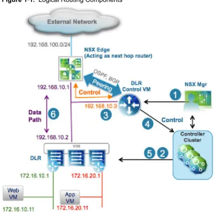
Figure 1‑1. Logical Routing Components
1 A DLR instance is created from the NSX Manager UI (or with API calls), and routing is enabled, leveraging either OSPF or BGP.
2 The NSX Controller leverages the control plane with the ESXi hosts to push the new DLR configuration including LIFs and their associated IP and vMAC addresses.
3 Assuming a routing protocol is also enabled on the next-hop device (an NSX Edge [ESG] in this example), OSPF or BGP peering is established between the ESG and the DLR control VM. The ESG and the DLR can then exchange routing information:
n The DLR control VM can be configured to redistribute into OSPF the IP prefixes for all the
connected logical networks (172.16.10.0/24 and 172.16.20.0/24 in this example). As a consequence, it then pushes those route advertisements to the NSX Edge. Notice that the next hop for those prefixes is not the IP address assigned to the control VM (192.168.10.3) but the IP address identifying the data-plane component of the DLR (192.168.10.2). The former is called the DLR "protocol address," whereas the latter is the "forwarding address."
n The NSX Edge pushes to the control VM the prefixes to reach IP networks in the external network.
In most scenarios, a single default route is likely to be sent by the NSX Edge, because it represents the single point of exit toward the physical network infrastructure.
4 The DLR control VM pushes the IP routes learned from the NSX Edge to the controller cluster. 5 The controller cluster is responsible for distributing routes learned from the DLR control VM to the
hypervisors. Each controller node in the cluster takes responsibility of distributing the information for a particular logical router instance. In a deployment where there are multiple logical router instances deployed, the load is distributed across the controller nodes. A separate logical router instance is usually associated with each deployed tenant.
6 The DLR routing kernel modules on the hosts handle the data-path traffic for communication to the external network by way of the NSX Edge.
NSX Services
The NSX components work together to provide the following functional services.
Logical Switches
A cloud deployment or a virtual data center has a variety of applications across multiple tenants. These applications and tenants require isolation from each other for security, fault isolation, and non-overlapping IP addresses. NSX allows the creation of multiple logical switches, each of which is a single logical broadcast domain. An application or tenant virtual machine can be logically wired to a logical switch. This allows for flexibility and speed of deployment while still providing all the characteristics of a physical network's broadcast domains (VLANs) without physical Layer 2 sprawl or spanning tree issues.
A logical switch is distributed and can span across all hosts in vCenter (or across all hosts in a cross-vCenter NSX environment). This allows for virtual machine mobility (vMotion) within the data center without limitations of the physical Layer 2 (VLAN) boundary. The physical infrastructure is not constrained by MAC/FIB table limits, because the logical switch contains the broadcast domain in software.
Logical Routers
Routing provides the necessary forwarding information between Layer 2 broadcast domains, thereby allowing you to decrease the size of Layer 2 broadcast domains and improve network efficiency and scale. NSX extends this intelligence to where the workloads reside for East-West routing. This allows more direct VM-to-VM communication without the costly or timely need to extend hops. At the same time, NSX logical routers provide North-South connectivity, thereby enabling tenants to access public networks.
Logical Firewall
Logical Firewall provides security mechanisms for dynamic virtual data centers. The Distributed Firewall component of Logical Firewall allows you to segment virtual datacenter entities like virtual machines based on VM names and attributes, user identity, vCenter objects like datacenters, and hosts, as well as traditional networking attributes like IP addresses, VLANs, and so on. The Edge Firewall component helps you meet key perimeter security requirements, such as building DMZs based on IP/VLAN constructs, and tenant-to-tenant isolation in multi-tenant-to-tenant virtual data centers.
The Flow Monitoring feature displays network activity between virtual machines at the application protocol level. You can use this information to audit network traffic, define and refine firewall policies, and identify threats to your network.
Logical Virtual Private Networks (VPNs)
SSL VPN-Plus allows remote users to access private corporate applications. IPsec VPN offers site-to-site connectivity between an NSX Edge instance and remote sites with NSX or with hardware routers/VPN gateways from 3rd-party vendors. L2 VPN allows you to extend your datacenter by allowing virtual machines to retain network connectivity while retaining the same IP address across geographical boundaries.
Logical Load Balancer
The NSX Edge load balancer distributes client connections directed at a single virtual IP address (VIP) across multiple destinations configured as members of a load balancing pool. It distributes incoming service requests evenly among multiple servers in such a way that the load distribution is transparent to users. Load balancing thus helps in achieving optimal resource utilization, maximizing throughput, minimizing response time, and avoiding overload.
Service Composer
Service Composer helps you provision and assign network and security services to applications in a virtual infrastructure. You map these services to a security group, and the services are applied to the virtual machines in the security group using a Security Policy.
Data Security provides visibility into sensitive data stored within your organization's virtualized and cloud environments and reports any data security violations.
NSX Extensibility
3rd-party solution providers can integrate their solutions with the NSX platform, thus enabling customers to have an integrated experience across VMware products and partner solutions. Data center operators can provision complex, multi-tier virtual networks in seconds, independent of the underlying network topology or components.
Preparing for Installation
2
This section describes the system requirements for NSX as well as the ports that must be open. This chapter includes the following topics:
n “System Requirements for NSX,” on page 15 n “Ports and Protocols Required by NSX,” on page 17 n “NSX and vSphere Distributed Switches,” on page 18
n “Example: Working with a vSphere Distributed Switch,” on page 20 n “NSX Installation Workflow and Sample Topology,” on page 27 n “Cross-vCenter NSX and Enhanced Linked Mode,” on page 29
System Requirements for NSX
Before you install or upgrade NSX, consider your network configuration and resources. You can install one NSX Manager per vCenter Server, one Guest Introspection per ESX™ host, and multiple NSX Edge instances per datacenter.
Hardware
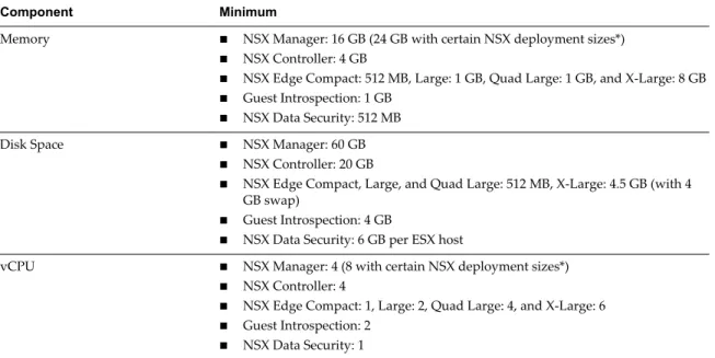
Table 2‑1. Hardware Requirements
Component Minimum
Memory n NSX Manager: 16 GB (24 GB with certain NSX deployment sizes*) n NSX Controller: 4 GB
n NSX Edge Compact: 512 MB, Large: 1 GB, Quad Large: 1 GB, and X-Large: 8 GB n Guest Introspection: 1 GB
n NSX Data Security: 512 MB
Disk Space n NSX Manager: 60 GB n NSX Controller: 20 GB
n NSX Edge Compact, Large, and Quad Large: 512 MB, X-Large: 4.5 GB (with 4
GB swap)
n Guest Introspection: 4 GB
n NSX Data Security: 6 GB per ESX host
vCPU n NSX Manager: 4 (8 with certain NSX deployment sizes*) n NSX Controller: 4
n NSX Edge Compact: 1, Large: 2, Quad Large: 4, and X-Large: 6 n Guest Introspection: 2
*As a general guideline, if your NSX managed environment contains more than 256 hypervisors, we recommend increasing NSX Manager resources to 8 vCPU and 24 GB of RAM. For specific sizing details contact VMware support.
For information about increasing the memory and vCPU allocation for your virtual appliances, see the following vSphere documentation pages (or the equivalent pages for your version of vSphere):
n Memory---https://pubs.vmware.com/vsphere-50/index.jsp#com.vmware.vsphere.vm_admin.doc_50/GUID-49D721 7C-DB6C-41A6-86B3-7AFEB8BF575F.html n vCPUs---https://pubs.vmware.com/vsphere-50/index.jsp#com.vmware.vsphere.vm_admin.doc_50/GUID-76FC7E 9F-8037-4C8E-BEB9-91C266C1EA9A.html
Software
For the latest interoperability information, see the Product Interoperability Matrixes at
http://partnerweb.vmware.com/comp_guide/sim/interop_matrix.php. These are the minimum required versions of VMware products.
n VMware vCenter Server 5.5 for single vCenter NSX support
n VMware ESXi 5.5 or later for each server for single vCenter NSX support n VMware vCenter Server 6.0 for cross-vCenter NSX support
n VMware ESXi 6.0 or later for each server for cross-vCenter NSX support
Note that for an NSX Manager to participate in a cross-vCenter NSX deployment the following conditions are required:
Component Version
NSX Manager 6.2 NSX Controller 6.2
All hosts Upgraded to vFabric version 6.2
To manage all NSX Managers in a cross-vCenter NSX deployment from a single vSphere Web Client, you must connect your vCenter Servers in Enhanced Linked Mode. See the VMware vSphere 6 Documentation
https://www.vmware.com/support/pubs/vsphere-esxi-vcenter-server-6-pubs.html.
Client and User Access
n If you added ESX hosts by name to the vSphere inventory, ensure that forward and reverse name
resolution is working. Otherwise, NSX Manager cannot resolve the IP addresses.
n Permissions to add and power on virtual machines
n Access to the datastore where you store virtual machine files, and the account permissions to copy files
to that datastore
n Cookies enabled on your Web browser, to access the NSX Manager user interface
n From NSX Manager, ensure port 443 is accessible from the ESX host, the vCenter Server, and the NSX
appliances to be deployed. This port is required to download the OVF file on the ESX host for deployment.
n One of the following Web browsers:
n Microsoft Internet Explorer 8, 9 (64-bit only), and 10
n Mozilla Firefox: the latest browser version, and the one previous version at the time NSX 6.2 is
produced
n Google Chrome: the latest browser version, and the one previous version at the time NSX 6.2 is
produced.
Ports and Protocols Required by NSX
The following ports must be open for NSX to operate properly.
Table 2‑2.
Source Target Port Protocol Purpose Sensitive SSL Authentication
Client PC NSX Manager 443 TCP NSX Manager Administrative Interface
No Yes PAM
Authentication Client PC NSX Manager 80 TCP NSX Manager VIB
Access No No PAMAuthentication ESXi Host vCenter
Server 80 TCP ESXi HostPreparation No No vCenter Server ESXi Host 80 TCP ESXi Host
Preparation No No
ESXi Host NSX Manager 5671 TCP RabbitMQ No Yes Rabbit MQ user/password ESXi Host NSX
Controller 1234 TCP User World AgentConnection No Yes NSX Controller NSX
Controller 2878,2888, 3888
TCP Controller Cluster
- State Sync No Yes IPsec NSX Controller NSX
Controller 7777 TCP Inter-ControllerRPC Port No Yes IPsec NSX Controller NSX
Controller 30865 TCP Controller Cluster- State Sync No Yes IPsec NSX Controller NTP Time
Server 123 TCP NTP clientconnection No Yes NoAuthentication NSX Manager NSX
Controller 443 TCP Controller toManager Communication
No Yes User/Password NSX Manager vCenter
Server 443 TCP TCP vSphere WebAccess No Yes NSX Manager vCenter
Server 902 TCP vSphere WebAccess No Yes NSX Manager ESXi Host 443 TCP Management and
provisioning connection
No Yes NSX Manager ESXi Host 902 TCP Management and
provisioning connection
No Yes NSX Manager DNS Server 53 TCP DNS client
connection No Yes NSX Manager Syslog Server 514 TCP Syslog connection No Yes NSX Manager NTP Time 123 TCP NTP client No Yes
Table 2‑2. (Continued)
Source Target Port Protocol Purpose Sensitive SSL Authentication
vCenter Server NSX Manager 80 TCP TCP Host
Preparation No Yes REST Client NSX Manager 443 TCP NSX Manager
REST API No Yes User/Password NSX Controller NTP Time
Server 123 UDP NTP clientconnection No Yes NoAuthentication NSX Manager DNS Server 53 UDP DNS client
connection No Yes NSX Manager Syslog Server 514 UDP Syslog connection No Yes NSX Manager NTP Time
Server 123 UDP NTP clientconnection No Yes VXLAN Termination End Point (VTEP) VXLAN Termination End Point (VTEP)
8472 UDP Transport network encapsulation between VTEPs
No Yes ESXi Host ESXi Host 6999 UDP ARP on VLAN
LIFs No Yes ESXi Host NSX Manager 8301,
8302 UDP DVS Sync No Yes NSX Manager ESXi Host 8301,
8302 UDP DVS Sync No Yes
NSX and vSphere Distributed Switches
In an NSX domain, NSX vSwitch is the software that operates in server hypervisors to form a software abstraction layer between servers and the physical network.
NSX vSwitch is based on vSphere distributed switches (VDSs), which provide uplinks for host connectivity to the top-of-rack (ToR) physical switches. As a best practice, VMware recommends that you plan and prepare your vSphere distributed switches before installing NSX for vSphere.
A single host can be attached to multiple VDSs. A single VDS can span multiple hosts across multiple clusters. For each host cluster that will participate in NSX, all hosts within the cluster must be attached to a common VDS.
For instance, say you have a cluster with Host1 and Host2. Host1 is attached to VDS1 and VDS2. Host2 is attached to VDS1 and VDS3. When you prepare a cluster for NSX, you can only associate NSX with VDS1 on the cluster. If you add another host (Host3) to the cluster and Host3 is not attached to VDS1, it is an invalid configuration, and Host3 will not be ready for NSX functionality.
Often, to simplify a deployment, each cluster of hosts is associated with only one VDS, even though some of the VDSs span multiple clusters. For example, suppose your vCenter contains the following host clusters:
n Compute cluster A for app tier hosts n Compute cluster B for web tier hosts
n Management and edge cluster for management and edge hosts
The following screen shows how these clusters appear in vCenter.
For a cluster design such as this, you might have two VDSs called Compute_VDS and Mgmt_VDS.
Compute_VDS spans both of the compute clusters, and Mgmt_VDS is associated with only the management and edge cluster.
Each VDS contains distributed port groups for the different types of traffic that need to be carried. Typical traffic types include management, storage, and vMotion. Uplink and access ports are generally required as well. Normally, one port group for each traffic type is created on each VDS.
For example, the following screen shows how these distributed switches and ports appear in vCenter.
Each port group can, optionally, be configured with a VLAN ID. The following list shows an example of how VLANs can be associated with the distributed port groups to provide logical isolation between different traffic types:
n Compute_VDS - Access---VLAN 130 n Compute_VDS - Mgmt---VLAN 210 n Compute_VDS - Storage---VLAN 520 n Compute_VDS - vMotion---VLAN 530 n Mgmt_VDS - Uplink---VLAN 100 n Mgmt_VDS - Mgmt---VLAN 110 n Mgmt_VDS - Storage---VLAN 420 n Mgmt_VDS - vMotion---VLAN 430
The DVUplinks port group is a VLAN trunk that is created automatically when you create a VDS. As a trunk port, it sends and receives tagged frames. By default, it carries all VLAN IDs (0-4094). This means that traffic with any VLAN ID can be passed through the vmnic network adapters associated with the DVUplink slot and filtered by the hypervisor hosts as the distributed switch determines which port group should receive the traffic.
If your existing vCenter environment contains standard vSwitches instead of distributed switches, you can migrate your hosts to distributed switches.
Example: Working with a vSphere Distributed Switch
This example shows how to create a new vSphere distributed switch (VDS); add port groups for management, storage, and vMotion traffic types; and migrate hosts on a standard vSwitch to the new distributed switch.
Note that this is just one example used to show the procedure. For detailed VDS physical and logical uplink considerations, see the VMware NSX for vSphere Network Virtualization Design Guide at
https://communities.vmware.com/docs/DOC-27683.
Prerequisites
This example assumes that each ESX host to be connected to the vSphere distributed switch has at least one connection to a physical switch (one vmnic uplink). This uplink can be used for the distributed switch and NSX VXLAN traffic.
Procedure
1 In the vSphere Web Client, navigate to a datacenter.
2 Click Create a Distributed Switch.
3 Give the switch a meaningful name based on the host cluster that will be associated with this switch. For example, if a distributed switch will be associated with a cluster of datacenter management hosts, you could name the switch VDS_Mgmt.
4 Provide at least one uplink for the distributed switch, keep IO control enabled, and provide a meaningful name for the default port group. Note that it is not mandatory to create the default port group. The port group can be manually created later.
By default, four uplinks are created. Adjust the number of uplinks to reflect your VDS design. The number of uplinks required is normally equal to the number of physical NICs you allocate to the VDS. The following screen shows example settings for management traffic on the management host cluster.
The default port group is just one of the port groups that this switch will contain. You will have an opportunity after the switch is created to add port groups for different traffic types. Optionally, you can untick Create a default port group option when creating a new VDS. This may in fact be the best practice; it's best to be explicit when creating port groups.
5 (Optional) Upon completion of the New Distributed Switch wizard, edit the settings of the default port group to place it in the correct VLAN for management traffic.
For example, if your host management interfaces are in VLAN 110, place the default port group in VLAN 110. If your host management interfaces are not in a VLAN, skip this step.
6 Upon completion of the New Distributed Switch wizard, right-click the distributed switch and select
New Distributed Port Group.
Repeat this step for each traffic type, making sure to provide a meaningful name for each port group and making sure to configure the proper VLAN ID based on the traffic separation requirements of your deployment. The following screens show example port group settings for storage and vMotion traffic.
The completed distributed switch and port groups looks like this.
7 Right-click the distributed switch, select Add and Manage Hosts, and select Add Hosts.
Attach all hosts that are in the associated cluster. For example, if the switch is for management hosts, select all of the hosts that are in the management cluster.
8 Select the options to migrate physical adapters, VMkernel adapters, and virtual machine networking.
9 Select a vmnic and click Assign uplink to migrate the vmnic from the standard vSwitch to the distributed switch. Repeat this step for each host that you are attaching to the distributed vSwitch. For example, this screen shows two hosts with their vmnic0 uplinks configured to migrate from their respective standard vSwitch to the distributed Mgmt_VDS-DVUplinks port group, which is a trunk port that can carry any VLAN ID.
10 Select a VMKernel network adapter and click Assign port group. Repeat this step for all network adapters on all hosts that you are attaching to the distributed vSwitch.
For example, this screen shows three vmk network adapters on two hosts configured to be migrated from the standard port groups to the new distributed port groups.
11 Move any VMs that are on the hosts to a distributed port group.
For example, this screen shows two VMs on a single host configured to be migrated from the standard port group to the new distributed port group.
After the procedure is complete, in the host CLI you can verify the results by running the following commands:
n ~ # esxcli network vswitch dvs vmware list Mgmt_VDS
Name: Mgmt_VDS
VDS ID: 89 78 26 50 98 bb f5 1e-a5 07 b5 29 ff 86 e2 ac Class: etherswitch
Num Ports: 1862 Used Ports: 5
Configured Ports: 512 MTU: 1600
CDP Status: listen Beacon Timeout: -1 Uplinks: vmnic0 VMware Branded: true DVPort:
Client: vmnic0
DVPortgroup ID: dvportgroup-306 In Use: true
Port ID: 24 Client: vmk0
DVPortgroup ID: dvportgroup-307 In Use: true
Port ID: 0 Client: vmk2
DVPortgroup ID: dvportgroup-309 In Use: true
Port ID: 17 Client: vmk1
DVPortgroup ID: dvportgroup-308 In Use: true
Port ID: 9
n ~ # esxcli network ip interface list vmk2
Name: vmk2
MAC Address: 00:50:56:6f:2f:26 Enabled: true
Portset: DvsPortset-0 Portgroup: N/A
Netstack Instance: defaultTcpipStack VDS Name: Mgmt_VDS
VDS UUID: 89 78 26 50 98 bb f5 1e-a5 07 b5 29 ff 86 e2 ac VDS Port: 16
VDS Connection: 1235399406 MTU: 1500
TSO MSS: 65535 Port ID: 50331650 vmk0
Name: vmk0
MAC Address: 54:9f:35:0b:dd:1a Enabled: true
Portset: DvsPortset-0 Portgroup: N/A
Netstack Instance: defaultTcpipStack VDS Name: Mgmt_VDS
VDS UUID: 89 78 26 50 98 bb f5 1e-a5 07 b5 29 ff 86 e2 ac VDS Port: 2
VDS Connection: 1235725173 MTU: 1500
TSO MSS: 65535 Port ID: 50331651 vmk1
Name: vmk1
MAC Address: 00:50:56:6e:a4:53 Enabled: true
Portset: DvsPortset-0 Portgroup: N/A
Netstack Instance: defaultTcpipStack VDS Name: Mgmt_VDS
VDS UUID: 89 78 26 50 98 bb f5 1e-a5 07 b5 29 ff 86 e2 ac VDS Port: 8
VDS Connection: 1236595869 MTU: 1500
TSO MSS: 65535 Port ID: 50331652 What to do next
Repeat the migration process for all vSphere distributed switches.
NSX Installation Workflow and Sample Topology
NSX installation involves the deployment of several virtual appliances, some ESX host preparation, and some configuration to allow communication across all of the physical and virtual devices.
VPN PV
VPN PV 2 3 4 5 1 NSX Manager vCenter ESXi Host Routing VXLAN DFW Prepare Hosts
Configure logical networking, deploy and configure NSX Edge Gateway(s) and configure network services Deploy NSX Manager Register with vCenter Deploy NSX Controllers
The process begins by deploying an NSX Manager OVF/OVA template and ensuring that the NSX Manager has full connectivity to the management interfaces of the ESX hosts that it will manage. After that, the NSX Manager and a vCenter instance need to be linked with each other through a registration process. This then allows a cluster of NSX controllers to be deployed. NSX controllers, like the NSX Manager, run as virtual appliances on ESX hosts. The next step is to prepare the ESX hosts for NSX by installing several VIBs on the hosts. These VIBs enable the Layer 2 VXLAN functionality, distributed routing, and distributed firewall. After configuring VXLANs, specifying virtual network interface (VNI) ranges, and creating transport zones, you can build out your NSX overlay topology.
This installation guide describes in detail each step in the process.
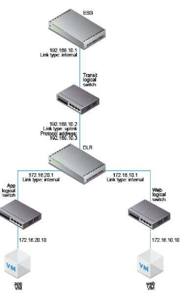
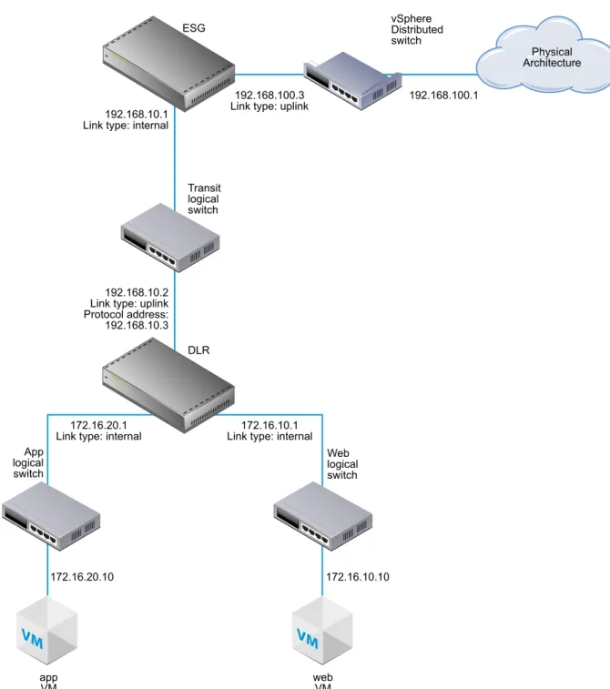
While being applicable to any NSX deployment, this guide also leads you through the creation of a sample NSX overlay topology that you can use for practice, guidance, and reference purposes. The sample overlay has a single NSX logical distributed router (sometimes called a DLR), an edge services gateway (ESG), and an NSX logical transit switch connecting the two NSX routing devices. The sample topology includes elements of an underlay as well, including two sample virtual machines. These virtual machines are each connected to a separate NSX logical switch that allow connectivity through the NSX logical router (DLR).
VM
VM
172.16.20.10 172.16.10.10
172.16.20.1
Link type: internal Link type: internal172.16.10.1 DLR App logical switch Web logical switch app
VM webVM
192.168.10.2 Link type: uplink Protocol address: 192.168.10.3 Transit logical switch 192.168.10.1
Link type: internal ESG
192.168.100.3
Link type: uplink 192.168.100.1
Physical Architecture vSphere
Distributed switch
Cross-vCenter NSX and Enhanced Linked Mode
vSphere 6.0 introduces Enhanced Linked Mode, which links multiple vCenter Server systems by using one or more Platform Services Controllers. This allows you to view and search the inventories of all linked vCenter Server systems within the vSphere Web Client. In a cross-vCenter NSX environment, Enhanced Linked Mode allows to you manage all NSX Managers from a single vSphere Web Client.
In large deployments where there are multiple vCenter Servers, it might make sense for you to use Cross-vCenter NSX with Enhanced Linked Mode for Cross-vCenter. These two features are complementary but separate from each other.
Combining Cross-vCenter NSX with Enhanced Linked Mode
In cross-vCenter NSX, you have a primary NSX Manager and multiple secondary NSX Managers. Each of these NSX Managers is linked to a separate vCenter Server. On the primary NSX Manager, you can create universal NSX components (such as switches and routers) that are viewable from the secondary NSX Managers.
When the individual vCenter Servers are deployed with Enhanced Linked Mode, all of the vCenter Servers can be viewed and managed from a single vCenter Server (sometimes called a single pane of glass). Thus, when cross-vCenter NSX is combined with Enhanced Linked Mode for vCenter, you can view and manage any of the NSX Managers and all of the universal NSX components from any of the linked vCenter Servers.
Using Cross-vCenter NSX Without Enhanced Linked Mode
Enhanced Linked Mode is not a prerequisite or requirement for cross-vCenter NSX. Without Enhanced Linked Mode, you can still create cross-vCenter universal transport zones, universal switches, universal routers, and universal firewall rules. However, without Enhanced Linked Mode in place, you must log in to the individual vCenter Servers to access each NSX Manager instance.
Further Information About vSphere 6.0 and Enhanced Linked Mode
For more information about vSphere 6.0 and enhanced linked mode, seehttps://blogs.vmware.com/consulting/2015/03/vsphere-datacenter-design-vcenter-architecture-changes-vsphere-6-0-part-1.html.
If you decide to use Enhanced Linked Mode see the vSphere 6.0 Installation and Setup Guide
http://pubs.vmware.com/vsphere-60/topic/com.vmware.vsphere.install.doc/GUID-7C9A1E23-7FCD-4295-9C B1-C932F2423C63.html or the vSphere 6.0 Upgrade Guide
http://pubs.vmware.com/vsphere-60/topic/com.vmware.vsphere.upgrade.doc/GUID-18B7B4BB-C24A-49CD-AE76-13285157B29F.html for the latest requirements for vSphere 6.0 and Enhanced Linked Mode.
Install the NSX Manager Virtual
Appliance
3
The NSX Manager provides the graphical user interface (GUI) and the REST APIs for creating, configuring, and monitoring NSX components, such as controllers, logical switches, and edge services gateways. The NSX Manager provides an aggregated system view and is the centralized network management component of NSX. NSX Manager is installed as a virtual appliance on any ESX host in your vCenter environment. The NSX Manager virtual machine is packaged as an OVA file, which allows you to use the vSphere Web Client to import the NSX Manager into the datastore and virtual machine inventory.
For high availability, VMware recommends that you deploy NSX Manager in a cluster configured with HA and DRS. Optionally, you can install the NSX Manager in a different vCenter than the one that the NSX Manager will be interoperating with. A single NSX Manager serves a single vCenter Server environment. In cross-vCenter NSX installations, make sure that each NSX Manager has a unique UUID. NSX Manager instances deployed from OVA files have unique UUIDs. An NSX Manager deployed from a template (as in when you convert a virtual machine to a template) will have the same UUID as the original NSX Manager used to create the template, and these two NSX Managers cannot be used in the same cross-vCenter NSX installation. In other words, for each NSX Manager, you should install a new appliance from scratch as outlined in this procedure.
The NSX Manager virtual machine installation includes VMware Tools. Do not attempt to upgrade or install VMware Tools on the NSX Manager.
Prerequisites
n Before installing NSX Manager, make sure that the required ports are open. See “Ports and Protocols Required by NSX,” on page 17.
n Make sure that a datastore is configured and accessible on the target ESX host. Shared storage is
recommended. HA requires shared storage, so that the NSX Manager appliance can be restarted on another host if the original host fails.
n Make sure that you know the IP address and gateway, DNS server IP addresses, domain search list, and
the NTP server IP address that the NSX Manager will use.
n Decide whether NSX Manager will have IPv4 addressing only, IPv6 addressing only, or dual-stack
network configuration. The host name of the NSX Manager will be used by other entities. Hence, the NSX Manager host name must be mapped to the right IP address in the DNS servers used in that network.
n Prepare a management traffic distributed port group on which NSX Manager will communicate. See “Example: Working with a vSphere Distributed Switch,” on page 20. The NSX Manager management interface, vCenter Server, and ESXi host management interfaces must be reachable by NSX Guest Introspection instances.
n The Client Integration Plug-in must be installed. The Deploy OVF template wizard works best in the
Firefox web browser. Sometimes in the Chrome web browser, an error message about installing the Client Integration Plug-in is displayed even though the plug-in is already successfully installed. To install the Client Integration Plug-in:
a Open a Web browser and type the URL for the vSphere Web Client.
b At the bottom of the vSphere Web Client login page, click Download Client Integration Plug-in. If the Client Integration Plug-In is already installed on your system, you will not see the link to download the plug-in. If you uninstall the Client Integration Plug-In, the link to download it will display on the vSphere Web Client login page.
Procedure
1 Locate the NSX Manager Open Virtualization Appliance (OVA) file.
Either copy the download URL or download the OVA file onto your computer. 2 In Firefox, open vCenter.
3 Select VMs and Templates, right-click your datacenter, and select Deploy OVF Template. 4 Paste the download URL or click Browse to select the file on your computer.
5 Tick the checkbox Accept extra configuration options.
This allows you to set IPv4 and IPv6 addresses, default gateway, DNS, NTP, and SSH properties during the installation, rather than configuring these settings manually after the installation.
6 Accept the VMware license agreements.
7 Edit the NSX Manager name (if required).select the location for the deployed NSX Manager The name you type will appear in the vCenter inventory.
The folder you select will be used to apply permissions to the NSX Manager. 8 Select a host or cluster on which to deploy the NSX Manager appliance.
For example:
9 Change the virtual disk format to Thick Provision, and select the destination datastore for the virtual machine configuration files and the virtual disks.
10 Select the port group for the NSX Manager.
For example, this screen shot shows the selection of the Mgmt_DVS - Mgmt port group.
11 Set the NSX Manager extra configuration options.
For example, this screen shows the final review screen after all the options are configured in an IPv4-only deployment.
Open the console of the NSX Manager to track the boot process.
After the NSX Manager is completely booted, log in to the CLI and run the show interface command to
verify that the IP address was applied as expected.
nsxmgr1> show interface
Interface mgmt is up, line protocol is up
index 3 metric 1 mtu 1500 <UP,BROADCAST,RUNNING,MULTICAST> HWaddr: 00:50:56:8e:c7:fa
inet 192.168.110.42/24 broadcast 192.168.110.255 inet6 fe80::250:56ff:fe8e:c7fa/64
Full-duplex, 0Mb/s
input packets 1370858, bytes 389455808, dropped 50, multicast packets 0 input errors 0, length 0, overrun 0, CRC 0, frame 0, fifo 0, missed 0 output packets 1309779, bytes 2205704550, dropped 0
output errors 0, aborted 0, carrier 0, fifo 0, heartbeat 0, window 0 collisions 0
Make sure that the NSX Manager can ping its default gateway, its NTP server, the vCenter Server, and the IP address of the management interface on all hypervisor hosts that it will manage.
Connect to the NSX Manager appliance GUI by opening a web browser and navigating to the NSX Manager IP address or hostname.
After logging in as admin with the password you set during installation, click View Summary and make sure that the following services are running: vPostgres, RabbitMQ, and NSX Management Services.
For optimal performance, VMware recommends that you reserve memory for the NSX Manager virtual appliance. A memory reservation is a guaranteed lower bound on the amount of physical memory that the host reserves for a virtual machine, even when memory is overcommitted. Set the reservation to a level that ensures NSX Manager has sufficient memory to run efficiently.
What to do next
Register the vCenter Server with the NSX Manager.
Register vCenter Server with NSX
Manager
4
NSX Manager and vCenter have a one-to-one relationship. For every instance of NSX Manager, there is one vCenter Server. This is true even if you are using the NSX cross-vCenter feature. After you install NSX Manager and ensure that the NSX management service is running, the next step is to register a vCenter Server with the NSX Manager.
Only one NSX Manager can be registered with a vCenter. Changing a vCenter registration can lead to an issue in which the change does not get communicated correctly to all affected vCenters and NSX Managers. For example, suppose you have the following initial configuration of NSX Managers and vCenters:
n NSX1 ----> VC1 n NSX2 ----> VC2
If you change the configuration on NSX1 so that its vCenter is VC2, the following occurs:
n NSX1 correctly reports that its vCenter is VC2. n VC2 correctly reports that its NSX Manager is NSX1. n VC1 incorrectly reports that its NSX Manager is NSX1. n NSX2 incorrectly reports that its vCenter is VC2.
In other words, if a vCenter is already registered with one NSX Manager, and then a different NSX Manager registers the same vCenter, the vCenter automatically removes its connection with the first NSX Manager and connects to the new NSX Manager. However, when you log in to the first NSX Manager, it continues to report a connection to the vCenter.
To prevent this issue, remove the NSX Manager plug-in from VC1 before registering it with VC2. For instructions, see “Safely Remove an NSX Installation,” on page 123.
Prerequisites
n The NSX management service must be running. You can verify this by using a Web browser to open the
NSX Manager appliance GUI at https://<nsx-manager-ip> and looking at the Summary tab.
n You must have a vCenter Server user account with the Administrator role to synchronize NSX Manager
with the vCenter Server. If your vCenter password has non-ASCII characters, you must change it before synchronizing the NSX Manager with the vCenter Server.
Procedure
1 In a Web browser, navigate to the NSX Manager appliance GUI at https://<nsx-manager-ip> or https://<nsx-manager-hostname>, and log in as admin with the password that you configured during NSX Manager installation.
2 Under Appliance Management, click Manage vCenter Registration. For example:
3 Edit the vCenter Server element to point to the vCenter Server's IP address or hostname, and enter the vCenter Server user name and password.
For the user name, the best practice is to enter [email protected] or an alternative account that you have created. Do not use the root account.
4 Check that the certificate thumbprint matches the certificate of the vCenter Server.
If you installed a CA-signed certificate on the CA server, you are presented with the thumbprint of the CA-signed certificate. Otherwise, you are presented with a self-signed certificate.
5 Do not tick Modify plugin script download location, unless the NSX Manager is behind a firewall type of masking device.
This option allows you to enter an alternate IP address for NSX Manager. Note that putting NSX Manager behind a firewall of this type is not recommended.
6 Confirm that the vCenter Server status is Connected. For example:
7 If vCenter Web Client is already open, log out of vCenter and log back in with the same Administrator role used to register NSX Manager with vCenter.
If you do not do this, vCenter Web Client will not display the Networking & Security icon on the
Home tab.
Click the Networking & Security icon and confirm that you can see the newly deployed NSX Manager.
What to do next
VMware recommends that you schedule a backup of NSX Manager data right after installing NSX Manager. If you have an NSX partner solution, refer to partner documentation for information on registering the partner console with NSX Manager.
Login to the vSphere Web Client and make sure that the Networking & Security icon appears on the Home tab. If you are already logged in, the icon will not appear. Re-login to the vSphere Web Client to view the new icon.
You can now install and configure NSX components.
Configure Single Sign On
5
SSO makes vSphere and NSX more secure by allowing the various components to communicate with each other through a secure token exchange mechanism, instead of requiring each component to authenticate a user separately. You can configure lookup service on the NSX Manager and provide the SSO administrator credentials to register NSX Management Service as an SSO user. Integrating the single sign on (SSO) service with NSX improves the security of user authentication for vCenter users and enables NSX to authenticate users from other identity services such as AD, NIS, and LDAP.
With SSO, NSX supports authentication using authenticated Security Assertion Markup Language (SAML) tokens from a trusted source via REST API calls. NSX Manager can also acquire authentication SAML tokens for use with other VMware solutions.
NSX caches group information for SSO users. Changes to group memberships will take up to 60 minutes to propagate from the identity provider (for example, active directory) to NSX.
Prerequisites
n To use SSO on NSX Manager, you must have vCenter Server 5.5 or later, and single sign on (SSO)
authentication service must be installed on the vCenter Server. Note that this is for embedded SSO. Instead, your deployment might use an external centralized SSO server.
For information about SSO services provided by vSphere, see http://kb.vmware.com/kb/2072435 and
http://kb.vmware.com/kb/2113115.
n NTP server must be specified so that the SSO server time and NSX Manager time is in sync.
Procedure
1 Log in to the NSX Manager virtual appliance.
In a Web browser, navigate to the NSX Manager appliance GUI at https://<nsx-manager-ip> or https://<nsx-manager-hostname>, and log in as admin with the password that you configured during NSX Manager installation.
2 Click the Manage tab, then click NSX Management Service. 3 Type the name or IP address of the host that has the lookup service.
If you are using vCenter to perform the lookup service, enter the vCenter Server's IP address or hostname, and enter the vCenter Server user name and password.
4 Type the port number.
Enter port 443 if you are using vSphere 6.0. For vSphere 5.5, use port number 7444. The Lookup Service URL is displayed based on the specified host and port. For example:
5 Check that the certificate thumb print matches the certificate of the vCenter Server.
If you installed a CA-signed certificate on the CA server, you are presented with the thumbprint of the CA-signed certificate. Otherwise, you are presented with a self-signed certificate.
6 Confirm that the Lookup Service status is Connected. For example:
What to do next
Assign a role to the SSO user.
Specify a Syslog Server
6
If you specify a syslog server, NSX Manager sends all audit logs and system events to the syslog server. Syslog data is useful for troubleshooting and reviewing data logged during installation and configuration.
Procedure
1 In a Web browser, navigate to the NSX Manager appliance GUI at https://<nsx-manager-ip> or https://<nsx-manager-hostname>, and log in as admin with the password that you configured during NSX Manager installation.
2 Click Manage Appliance Settings. For example:
3 From the Settings panel, click General. 4 Click Edit next to Syslog Server.
5 Type the IP address or hostname, port, and protocol of the syslog server.
If you do not specify a port, the default UDP port for the IP address/host name of the syslog server is used.
For example:
6 Click OK.
vCenter Server remote logging is enabled, and logs are stored in your standalone syslog server.
Install and Assign NSX for vSphere
License
7
You can install and assign an NSX for vSphere license after NSX Manager installation is complete by using the vSphere Web Client.
Before purchasing and activating an NSX for vSphere license, you can install and run the software in evaluation mode. When run in evaluation mode, intended for demonstration and evaluation purposes, NSX components are completely operational immediately after installation, do not require any licensing
configuration, and provide full functionality for 60 days from the time you first activate them.
Procedure
1 Log in to the vSphere Web Client.
2 Click Administration and then click Licenses. 3 Click the Solutions tab.
4 From the drop-down menu at the top, select Assign a new license key. 5 Type the license key and an optional label for the new key.
6 Click Decode.
Decode the license key to verify that it is in the correct format, and that it has enough capacity to license the assets.
7 Click OK.
What to do next
Obtain and install an NSX for vSphere license within 60-day the evaluation period.
The Licensing team does not issue licenses or extend the license evaluation period if you have already evaluated a product. If you want to evaluate a product beyond the evaluation period, contact our Sales team. For more information about NSX licensing, see
Deploy NSX Controllers
8
NSX controller is an advanced distributed state management system that provides control plane functions for NSX logical switching and routing functions. It serves as the central control point for all logical switches within a network and maintains information about all hosts, logical switches (VXLANs), and distributed logical routers. Controllers are required if you are planning to deploy 1) distributed logical routers or 2) VXLAN in unicast or hybrid mode.
No matter the size of the NSX deployment, VMware requires that each NSX Controller cluster contain three controller nodes. Having a different number of controller nodes is not supported.
Prerequisites
n Before deploying NSX controllers, you must deploy an NSX Manager appliance and register vCenter
with NSX Manager.
n For the controller appliance VM datastore, make sure to use low-latency storage for the ZooKeeper
partitions that the controllers use.
n Determine the IP pool settings for your controller cluster, including the gateway and IP address range.
DNS settings are optional. The NSX controller IP network must have connectivity to the NSX Manager and to the management interfaces on the ESXi hosts.
n Make sure that at least one host in the management cluster is powered on. The NSX controllers are
Procedure
1 In vCenter, navigate to Home > Networking & Security > Installation and select the Management tab. For example:
2 In the NSX Controller nodes section, click the Add Node ( ) icon. 3 Enter the NSX Controller settings appropriate to your environment.
The network that the controller is connected to can be the management port group on the Distributed Virtual Switch that spans the environment. However, it doesn't need to be as long as the controller can talk to the NSX Manager, other controllers, and to hosts via IPv4.
For example:
4 If you have not already configured an IP pool for your controller cluster, configure one now by clicking
New IP Pool.
Individual controllers can be in separate IP subnets, if necessary. For example:
5 Type and re-type a password for the controller.
NOTE Password must not contain the username as a substring. Any character must not consecutively
repeat 3 or more times.
The password must be at least 12 characters and must follow 3 of the following 4 rules:
n At least one upper case letter n At least one lower case letter n At least one number
n At least one special character
6 After the first controller is completely deployed, deploy two additional controllers. Having three controllers is mandatory.
When successfully deployed, the controllers have a Normal status and display a green check mark.
SSH to each controller and make sure they can ping the host management interface IP addresses. If the ping fails, make sure all controllers have the correct default gateway. To view a controller routing table, run the
show network routes command. To change a controller's default gateway run the clear network routes
command followed by the add network default-route <IP-address> command. Run the following commands to verify the control cluster is behaving as expected.
n show control-cluster status
Type Status Since
---Join status: ---Join complete 05/04 02:36:03 Majority status: Connected to cluster majority 05/19 23:57:23 Restart status: This controller can be safely restarted 05/19 23:57:12
Node UUID: ff3ebaeb-de68-4455-a3ca-4824e31863a8 Role Configured status Active status
---api_provider enabled activated
persistence_server enabled activated switch_manager enabled activated logical_manager enabled activated directory_server enabled activated
For Join status, verify the controller node is reporting Join Complete. For Majority status, verify the controller is connected to the cluster majority. For Cluster ID, all the controller nodes in a cluster should have the same cluster ID.
For Configured status and Active status, verify that the all the controller roles are enabled and activated.
n show control-cluster startup-nodes
192.168.110.101, 192.168.110.102, 192.168.110.103
The output shows the assigned IP addresses for the three controller nodes. These IP addresses come from the controller IP pool.
n show control-cluster roles
Listen-IP Master? Last-Changed Count api_provider Not configured Yes 06/02 08:49:31 4 persistence_server N/A Yes 06/02 08:49:31 4 switch_manager 127.0.0.1 Yes 06/02 08:49:31 4 logical_manager N/A Yes 06/02 08:49:31 4 directory_server N/A Yes 06/02 08:49:31 4
One controller node will be the master for each role. In this example, a single node is the master for all roles.
If a master NSX controller instance for a role fails, the cluster elects a new master for that role from the available NSX controller instances.
NSX controller instances are on the control plane, so an NSX controller failure does not affect data plane traffic.
n show control-cluster connections
role port listening open conns ---api_provider api/443 Y 2
---persistence_server server/2878 Y 2
client/2888 Y 1 election/3888 Y 0
---switch_manager ovsmgmt/6632 Y 0
openflow/6633 Y 0
---system cluster/7777 Y 0
This command shows the intra-cluster communication status.
The controller cluster majority leader listens on port 2878 (as shown by the “Y” in the “listening” column). The other controller nodes will have a dash (-) in the “listening” column for Port 2878. All other ports should be listening on all three controller nodes.
The open conns column shows the number of open connections that the controller node has with other controller nodes. In a 3-node controller cluster, the controller node should have no more than two open connections.
What to do next
CAUTION While a controller status is Deploying, do not add or modify logical switches or distributed
routing in your environment. Also, do not continue to the host preparation procedure. After a new controller is added to the controller cluster, all controllers are inactive for a short while (no more than 5 minutes). During this downtime, any operation related to controllers---for example, host preparation---might have unexpected results. Even though host preparation preparation---might seem to complete successfully, the SSL certification might not establish correctly, thus causing issues in the VXLAN network.
If you need to delete a deployed controller, see “Recover from an NSX Controller Failure,” on page 122. On the hosts where the NSX controller nodes are first deployed, NSX enables automatic VM
startup/shutdown. If the controller node VMs are later migrated to other hosts, the new hosts might not have automatic VM startup/shutdown enabled. For this reason, VMware recommends that you check all hosts in the cluster to make sure that automatic VM startup/shutdown is enabled. See
http://pubs.vmware.com/vsphere-60/index.jsp?topic=%2Fcom.vmware.vsphere.vm_admin.doc %2FGUID-5FE08AC7-4486-438E-AF88-80D6C7928810.html.